

Electrical problems are every car owner’s worst nightmares; so many wires and complicated components to inspect. Luckily for you, automotive wiring diagrams are there to help you speed up the whole process. Obviously, you’ll first need to understand the different codes and symbols for electrical diagrams to be beneficial. To assist you with that, we have created this quick guide on how to read car wiring diagrams to troubleshoot and fix simple electrical system problems in no time.
And don’t worry if you aren’t that tech-savvy: wiring diagrams"}” data-sheets-userformat=”{"2":12803,"3":{"1":0},"4":{"1":2,"2":10066329},"12":0,"15":"Verdana","16":14}”>understanding automotive wiring diagrams is actually much easier than it seems!
Most Common Symbols and their Meaning
Single Wires

In electrical diagrams, every straight black line represents a wire. Pretty simple right? On a diagram, there’s no visual difference between wire gauges and materials. All wires are then identified using a color code and a number, but we’ll see more about that later in this article.
Connected Wires
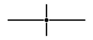
The symbol used to show that two wires are connected is a tiny black dot. These wires are included in the same system or at least use the same power source or ground connector.
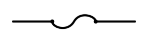
Non-Connected Wires

If wires run in the same harness but cross over each other without being connected, the symbol is the same but with a little bump. When testing for continuity, these wires shouldn’t trigger your multimeter. If they do, the wires may be skinned somewhere and may cause a short-circuit in the system.
Battery / Power Source
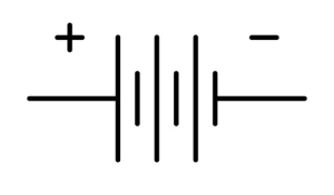
This is the symbol for a standard 6-cell 12v car battery. Some diagrams may use a simplified version which is only two vertical bars instead of 6. On more complicated electrical systems or electronic modules, diagrams can quickly become filled with tons of lines and symbols, making them hard to read for the user. Depending on the manual editor, this symbol could indicate a 2 cells battery or have been used simply to make the whole diagram a little easier to read.
Fuses
Fuses serve as a means of protection for the electrical system. If something goes wrong and a wire is damaged and causes a short-to-ground condition, the fuse will instantly blow, preventing any more damage to the whole circuit. It’s no surprise that blown fuses are the cause of most electrical malfunctions. When trying to diagnose an electrical problem, always start by inspecting the fuses related to the faulty circuit, and 9 out of 10 times, you’ll find the problem right away.
On electrical diagrams, fuses are often located on a different page than the circuit they protect. Most online auto repair manuals have a dedicated section reserved for all the fuses, relays, and pretty much everything included in the fuse boxes called Power Distribution diagram to make things easier.
In addition, most diagrams will indicate if the fuses are “hot at all times” or not, letting the reader know if the fuse is constantly powered by the battery or only when the ignition key is in the ON position. Never forget to check that out before testing a fuse, or you could end up with an incorrect diagnosis.
Grounds
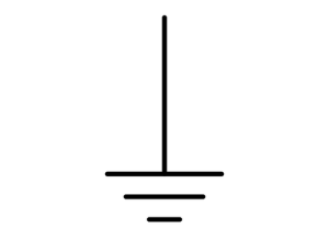
On a car, the ground is always the body of the vehicle. I should say that the ground is the negative post of the battery, but since a wire goes straight from the post to the body, every metal part touching the body is also considered ground.
The most important components all have their dedicated ground wire to ensure that it’s grounded at all times. For example, the engine and the transmission have one or more large braided ground wires connected to the body. If for some reason, one of the wires was damaged, the corresponding unit should still keep on working since the engine is bolted onto the transmission and vice-versa. On some occasions, though, the added resistance induced by the longer circuit may cause sensible electronic components to go haywire and cause various problems.
The alternator, for instance, usually gets its ground from the alternator bracket bolted onto the engine head. If the engine ground is broken, the alternator may not be able to produce enough current to power all the accessories simultaneously and may cause worrying charging system problems.
Read more:


Switches
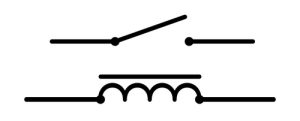
Toggle Switches

There is all kind of switches on a vehicle, but the most common one is the toggle switch. A good example of this is a simple dome light switch. Push to one side to turn the component on and to the other side to turn it back off. These are widely used throughout the car because of their simplicity and relative reliability.
Push Button Switches

These are a little less common but still used a lot by car manufacturers. Think of the rear defrost and emergency flasher switches. The same motion is used to trigger it on and off.
Selector Switches
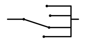
This type of switch is used to either control more than one accessory at the same time or when there’s more than one possible selection. The Park/Neutral position switch is probably the best example. Only one input for multiple different possible outputs (P, D, etc.).
Multi-function switches like the headlight/flasher switch are somewhat different but still work based on the same principle. They are basically more than one selector switch included in the same unit.
Relays
Relays are remote-controlled switches. They allow car manufacturers to install low-voltage switches inside the cabin to control higher-voltage components. They began to be widely used when manufacturers started to replace bulky headlight switches on the dashboard in favor of small combo switches on the steering columns.
Their working principle is quite simple. A low-voltage switch is used to turn on and off a small electromagnet, which will activate a bigger switch to provide power to components such as headlights, cooling fans, fuel pumps, etc. Almost every major system and component on your vehicle is controlled using a relay.
Since the amount of power flowing through them is often higher than most other switch types, the smaller internal components are often prone to failure. It’s not rare to see a fuel pump relay burn and stop clicking.
Light Bulbs

This one is self-explanatory. Everyone knows what light bulbs are and what their purpose is. But in an electrical diagram, light bulbs are everywhere. It’s important to understand that headlights and blinkers are not the only light bulbs on your car. In fact, newer vehicles use light bulbs for pretty much every electrical component inside the cabin to indicate if they are turned ON or OFF.
Nowadays, it’s also common to see light bulbs enclosed in door panels, floors, under the dash, inside the parking brake switch, and even under the seats for the owner’s convenience.
Especially for light bulbs under seats and other locations where salt and water can easily reach, open circuits and bad connection problems often lead to lighting system failures. Being able to quickly identify light bulb symbols and locate them in an electrical circuit might be helpful to speed up the whole troubleshooting process.
Resistors
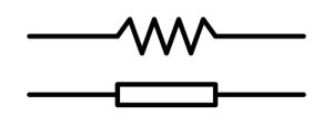
Resistors are small electronic components used to apply a specific resistance to the current flow in an electronic circuit. There’s not much to do with them as an auto mechanic since they can rarely be replaced by themselves. They are reliable and rarely come into problems. If you are unlucky enough to find a burnt resistor in the circuit you are inspecting, the problem most probably lies elsewhere. A blown resistor is often the result of a faulty module driving too much power inside the circuit or an internal short-to-ground condition. In both cases, a defective resistor is usually the consequence of another problem and hardly ever its cause.
It still helps to know what resistors are, what they do, and how to find them, if only to not worry too much about it. Simply learn what the symbol looks like so you know what it is when you come across one in a car wiring diagram.
It’s worth mentioning that different manuals may use two other symbols to represent resistors. Keep that in mind if you use more than one type of repair manual, or you might end up with false test results.
Diodes
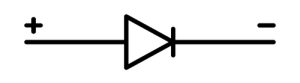
This other small electronic component has the property of only letting the current flow in one direction. It is either used to protect sensible low-voltage elements from being damaged by an excess of voltage going through expensive modules and components or to redirect the current in a circuit like inside an alternator. If over-voltage occurs, a diode will react exactly as a fuse and will instantly blow. You’ll then need to find its location using your vehicle’s wiring diagram and replace it.
Motors

This symbol is a bit more tricky to describe since the “Motor” logo can refer to multiple components. As a rule of thumb, one could say that they usually refer to the power-consuming element in the system you are troubleshooting. For example, power window regulators are represented as motors on the power window diagram—the same thing applies to the sunroof motor, power door locks, the wiper motor, power seats, and so on.
Solenoids

Solenoids are small electromagnetic switches, except that these move back and forth when submitted to an electric current. They usually serve to open or close a fluid or air passage, and they have numerous different uses in a vehicle. Injectors are the most well-known solenoid, but you could also think of the starter solenoid and automatic transmission solenoids connected to the valve body. They are so similar to switches that their symbol is one-half of the relay symbol. And for a good reason. The electromagnet making the relay click is also, theoretically speaking, a solenoid.
Color Codes

All automotive wires are color-coded to help you quickly and efficiently identify a specific wire in a wire harness or a connector. Colors often differ from one car manufacturer to another, but the code used to identify them in an automotive wiring diagram is always the same.
The color will be noted using an abbreviation beside each wire following the same pattern: Wire color/Stripe color. For example, a white wire with a black stripe on the side would be identified as WHT/BLK. A dark green wire with a yellow stripe could be named DG/YE. One repair manual may use a 3 letter color-coding system, while others may use 2-letter abbreviations only. In all cases, make sure to refer to the color code chart at either the beginning or the end of the manual for more information on how the different wire colors are classified.
Connector Numbers and Locations
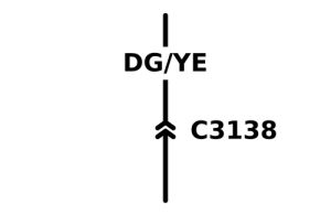
For the same reason, color codes are used, and connectors and wires are also identified using a number corresponding to a physical location or a page in the manual. In both cases, the number will let you know where to go to quickly find where the connector is located on the vehicle.
This comes in pretty handy when you need to find an open-loop or a short-to-ground condition in a specific wire. Instead of removing all the carpeting and trims to follow the wires all the way to where the problem is, you can simply identify all the connectors first, find their location and only remove the trims necessary to gain access to them.
To sum it all up…
Learning to read car wiring diagrams is a tremendous skill to add to your auto mechanic skillset. Being able to master this competency will not only help you find solutions to common electrical problems a lot faster but will also give you a big headstart compared to less qualified technicians. And it’s not that hard at all. Once you get the hang of the most basic notions, all you’ll need is a bit of practice, and you should be able to fix most electrical system troubles like a pro.


Thanks. Very simplified and understandable. Keep i up!
Thank you for the feedback!
Need more understanding in wiring … I need some assistance
Hi Dickson,
Feel free to contact us here:
https://www.emanualonline.com/blog/contact-us/
We’ll do all we can to help…
Chad
indeed, thank you. very well done. don’t know if you can answer a specific but……two wires to a compressor motor on a Buick….both white with black dots….is it possible polarity does not matter in this case?
hum… it would depend on which wires you are talking about…. are you talking about the clutch or the pressure sensor?
What would T/O mean?
Hum… that’s a bit hard to tell without having a look at the diagram first but if I had to guess, I would say it’s the wire’s color code…
Probably something like a Tan wire with an Orange stripe? In all cases, the color code for your specific car model is always explained in details in the first pages of your repair manual, usually in a section called “How to Use this Manual” or “How to Read Wiring Diagram”
Something like this:

I hope it helps!
What is the problema when the indicador of fuel lights on in tanks full situación ,its mostly occurs when starts stepping brakes to reduce speed Up to detaine the car , my car is Fiat Doblo
Thanks
If the fuel light comes up when stepping on the brakes, it usually means the fuel level is only barely above the minimum level and when the car shifts forward when pressing the brakes, the level goes low enough to trigger the light…
If fuel is full, there might be a problem with the fuel level sender itself
I have a 2005 mustang convertible i was going to the store and it would not start. When you turn the key nothing comes on no interior lights nothing. I had a new intake fuel pump tune up sensors and seals back in March. Could you please help me with what could be wrong? I’m a single female and tired of feeling like cause I’m a female shops can get over on you……. please help if you can
Hi!
First of all, if there’s no power, no lights nothing, it doesn’t have anything to do with the fuel pump or any of that. That been said, there could be several reasons why there’s no power. I would start by testing the battery, then check the main fuse and body ground and see if that’s all good. If it is, next could be an ignition switch problem or a misconnection somewhere… honestly it’s really hard to tell without being able to run a couple of tests on the vehicle.
Nonetheless, here are some posts that could help here:
How to Use a Multimeter
How to Start a Car When the Battery is Dead
How to Test an Ignition Switch
Don’t hesitate to follow up with what you find, I’d be happy to help!
03 civic 1.7, last owner said battery was replaced used, started lose connection, died upon tightening. Now start since. Flashing green key. No fuel pump on, no spark at plugs. Does crank. DLC not working scanners are acknowledging being plugged in but not communicating, we assume maybe immobilizer? Or ecu issue? That’s why key is flashing? But we cannot re program a new computer, key or ignition if we can’t communicate. I tested the pins in the dlc, with the ignition off? Should it have been on? The pins I was suppose to text for voltage read 0 and the one for ohms read 0 as well. If I am testing correctly what is my next step to find where the wire is going and or what my issue is? Thank you so much.
Unfortunately, it’s incredibly hard to troubleshoot issues online without being able to run tests of any sort.
But have you checked if the main fuse was good? I would suspect the battery’s polarity might have been reverse at some point, which could be causing most of these symptoms.
Thanks for the write-up Jean-Claude. Helped me a lot. I’m installing electronic dampening shocks on the rear my 2016 Audi S6. The previous shocks I had were aftermarket. The shocks I bought are OEM Audi with two wires coming out, green and brown. I’m assuming brown is the hot wire. The connectors I purchased have a 1 and 2 near the holes where the wires will clip into. I believe 2 is for the brown wire and 1 for the green based on the diagram at the end of this post. Does that sound correct using this diagram? https://imgur.com/2Wvski9
Hi!
The image you shared doesn’t seem to work unfortunately…
Can you try posting it again?
I don’t believe I can share an image directly on here but will try in a separate post. Try this link: https://imagizer.imageshack.com/img923/154/KYaPyP.png
Hum… the image does work, although, I might need more details and might be hard to do that through blog comments.
Can you come on our Facebook group and post your question there?
https://www.facebook.com/groups/238724601400735
Would be much easier to communicate this way and tons of other like-minded DIY’ers (who could be much well versed than I am in Audis) could chime in too.
I finally found an explanation I can understand!!! Thank you for your way with the written word- it has made it much easier to interpret the wiring diagrams for my VW beetle.