

2006-2014 Polaris 4-Stroke Snowmobile Service & Repair Manual
What's Included?
Fast Download Speeds
Online & Offline Access
Access PDF Contents & Bookmarks
Full Search Facility
Print one or all pages of your manual
2007-2014 FOU
SNOWM
SERVICE MAN
PN 992429

POLARIS®
2006-2014 Four Stroke Snowmobile Service
Manual
FOREWORD
The information printed within this publication includes the latest product information at time of print. The most recent
version of this Service Manual is available in electronic format at www.polarisdealers.com.
This Service Manual is designed primarily for use by certified Po laris Master Service Deale r® technicians in a properly
equipped shop and should be kept available for reference. All references to left and right side of the vehicle are from
the operator's perspective when seated in a normal riding position .
Some procedures outlined in this manual require a sound knowledge of mechanical theory, tool use, and shop
procedures in order to perform the work safely and correctly. Technicians should read the text and be familiar with the
service procedures before starting any repair. Certain procedures require the use of special tools. Use only the proper
tools as specified. If you have any doubt as to your ability to perform any of the procedures outlined in this Service
Manual, contact an authorized dealer for service.
We value your input and appreciate any assistance you can provide in helping make these publications more useful.
Please provide any feedback you may have regarding this manual. Authorized dealers can submit feedback using 'Ask
Polaris' . Click on 'Ask Po laris', and then click on 'Service Manual I Service Literature Question '.
Consumers, please provide your feedback in writing to: Polaris Industries Inc. ATTN : Service Publications Department,
2100 Hwy 55, Medina, MN 55340.
Publication Printed August 2013 (PN 9924290)
© Copyright 2013 Pol aris Sales Inc. All information con tained within this publicati on is based on the latest product information at the time of publication . Due to constant
improvements in the desi gn and quality of prod uction components, some minor discrepancies may result between the actual vehicle and the information presented in this
publication. Depictions an d/or procedures in this publication are intended for reference use only. No li abil ity can be accepted for omissions or inaccuracies. Any repri nting
or reuse of the depictions and/or procedures contained within , whether whole or in part , is expressly prohibited . Printed in U.S.A.
UNDERSTANDING SAFETY LABELS AND DIRECTIONS
Throughout this manual, important information is brought to your attention by the following symbols:
A wARNING
SAFETY ALERT WARNING indicates a potential hazard that may result in severe injury or death to the operator,
bystander or person(s) inspecting or servicing the vehicle.
A CAUTION
SAFETY ALERT CAUTION indicates a potential hazard that may result in minor personal injury or damage to the
vehicle.
CAUTION
CAUTION indicates special precautions that must be taken to avoid vehicle damage or property damage.
NOTE:
NOTE provides key information by clarifying instructions.
IMPORTANT:
IMPORTANT provides key reminders during disassembly, assembly and inspection of components.
TRADEMARKS
POLARIS ACKNOWLEDGES THE FOLLOWING PRODUCT(S) MENTIONED IN THIS MANUAL:
Loctite, Registered Trademark of the Loctite Corporation
Nyogel, Trademark of Wm. F. Nye Co.
Fluke, Registered Trademark of John Fluke Mfg. Co .
Mity-Vac, Registered Trademark of Neward Enterprises, Inc.
Torx, Registered Trademark of Textron
Hilliard, Trademark of the Hilliard Corporation
Warn , Trademark of Warn Industries
FOX, Registered Trademark of FOX RACING SHOX
RydeFX, Registered Trademark of ArvinMeritor
Some Polaris factory publications can be downloaded from www.polarisindustries.com, purchased from
www.purepolaris.com or by contacting the nearest Polaris dealer.

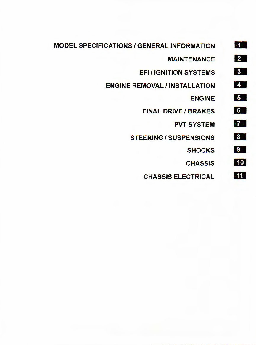
MODEL SPECIFICATIONS I GENERAL INFORMATION
Ill
MAINTENANCE Dl
EFI/IGNITION SYSTEMS Ill
ENGINE REMOVAL /INSTALLATION Dl
ENGINE Dl
FINAL DRIVE I BRAKES Dill
PVTSYSTEM Dl
STEERING I SUSPENSIONS Ill
SHOCKS Dl
CHASSIS m
CHASSIS ELECTRICAL m

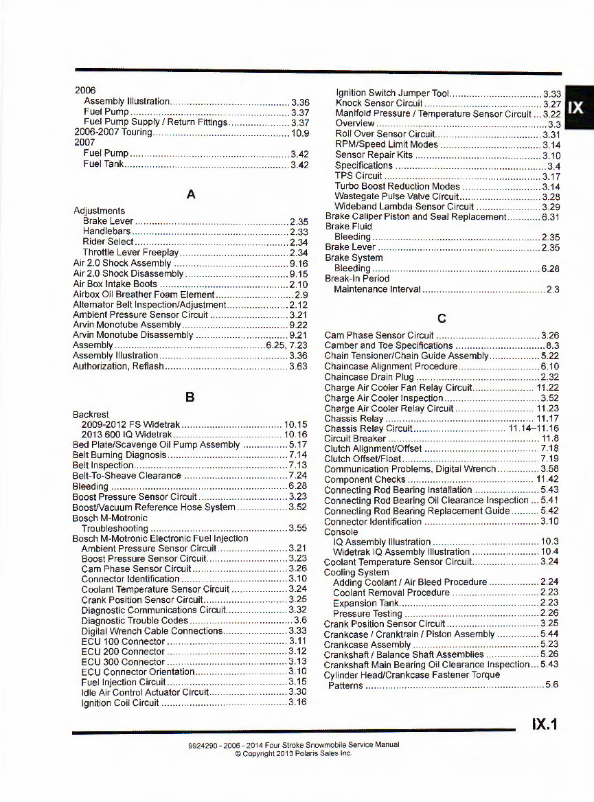
2006
Assembly Illustration ...... .... ... .... .. .. .. .. ......... .. .. .. ... 3.36
Ignition Switch Jumper Tool .. .... .. .. .. .. .. .. .. .. .. .... .. .. . 3.33
Knock Sensor Circuit .. .. .... .... .. .. .. .... .. .. .... .. .. .. .. .. .. 3.27
Fuel Pump ... .. .. .... ... .... .. .. .. .... .. .. ... .. .. . .. .. ....... .. .... 3.37
Fuel Pump Supply I Return Fittings .... .. .... .. .. .. .. .... 3.37
Manifold Pressure I Temperature Sensor Circuit ... 3.22
Overview ......... .. ............. .. .... .. .. .. ......................... 3.3
2006-2007 Touring .. ..... . .. . .. .. ....... .. .. ... .. .. . .. .. .. . .. .. ... . 10.9
Roll Over Sensor Circuit .. .. .... .. .. .. .. .. .. . .. .. ..... ..... ... 3.31
2007
Fuel Pump ....... .. .. . .. .. ....... .. .. .. .. .. .. .. .. ... .. .... .. .. .. . .. 3.42
Fuel Tank . .. .. .. ... .. .. .. ... .. .. . .. .. .... .. .. ................. .. .. .. 3.42
RPM/Speed Limit Modes .. .. .. .. . .. .. ..... .. .. .. .. ..... .. ... 3.14
Sensor Repair Kits .. ...... .. .. .. .. .. ........ .. .. .. .. .. .... .. .. . 3.10
Specifications .......................................... .. .. .. .. .... 3.4
TPS Circuit .. .... .... .. ...... .... .. .. .. .. .. .... .. .. .. .. .. .. .. ...... 3.17
A
Turbo Boost Reduction Modes .. ........ .. ... .. . .. .... .. .. 3.14
Wastegate Pulse Valve Circuit.. .. .. .. .. .. .. ...... .... .. .. . 3.28
Adjustments
Brake Lever .. .. .. .. .. .. .. ... . .. .... .. .. .. .. ... ... .. .. . .. .. ........ 2 .35
Handlebars ....................... .. ... .............. .. . .. ......... 2.33
Rider Select .. ...... ...... .. . .. ........ ...... .. .. . .. .. ........ .. ... 2.34
Throttle Lever Free play .... .. ... .. .. .. .. . .. .. . .. .. .. .. . .. ..... 2.34
Air 2.0 Shock Assembly .. .. .... ... .. .... .. .... .. ........ . .. .. .. . 9.16
Air 2.0 Shock Disassembly .. ........................ .. .. .. .... . 9.15
Air Box Intake Boots .. ...... .... .. .. .. .. .. .. ...... .... .. .. ... .... . 2.10
Airbox Oil Breather Foam Element.. .. .. .. .. .. ........ ........ 2.9
Wideband Lambda Sensor Circuit .... ...... .. .. .... .. .. . 3.29
Brake Caliper·Piston and Seal Replacement.. .......... 6.31
Brake Fluid
Bleeding .. .. .... ... .. .. .......... .. ........ . .. .. . .. .. .. . .. ... .. .. .. . 2.35
Brake Lever .. ....... .. . .. .. .. .... ... .. .... .. .. . .. .. ..... . .. .. ... .. .. . 2.35
Brake System
Bleeding ............. ............... .. . .. ..... .. ..... .. .. .. .. .. .. .. . 6.28
Break- In Period
Maintenance Interval .. .... .... .. .... ...... .. .. . .. .. .. . .. .. .. .... 2.3
Alternator Belt Inspection/Adjustment .... ..... .. ........... 2.12
Ambient Pressure Sensor Circuit .. .. ...... .. .. . .. .. .... .. .. . 3.21
Arvin Monotube Assembly .... .. .... .. .. .. .. .. .. .. .. .... .. .. .. .. 9.22
c
Arvin Monotube Disassembly .. ...... .. .... .. .. . .. .... .. .. .. .. 9.21 Cam Phase Sensor Circuit .. .. .. .. .. .. .. .... .. .... .. .. .. .. .... . 3.26
Assembly ......... .. .... .. .. ..... .. ... .... .. .. ............... .. 6.25, 7.23 Camber and Toe Specifications ........ .. .... .. .. .... .. . .. .. .. . 8.3
Assembly Illustration .... .. ....... . .. .............................. 3.36 Chain Tensioner/Chain Guide Assembly ....... .. .. .. .. ... 5.22
Authorization, Reflash .. .. .... .. ....... .. .... .... .. ............... 3.63 Chaincase Alignment Procedure ..... .. ............... .. .. . .. 6.10
Chaincase Drain Plug .......... .. .. ...... .. .... ...... . .. ........ . 2.32
8
Charge Air Cooler Fan Relay Circuit .. .. .. .. .... .. .. .. .. .. 11 .22
Charge Air Cooler Inspection .. .. .. .. .. ...... .. .. .. .. .. .. .. .. .. 3.52
Backrest
2009-2012 FS Widetrak .. .. .. .. .. .... .. .. .. .. .. .. .. .. ...... 10.15
2013 600 IQ Widetrak .. ............ .. .. .... .. .... .. .. .... .. . 10.16
Bed Plate/Scavenge Oil Pump Assembly .... . .. .... .. .. . 5.17
Belt Burning Diagnosis .. .. .. .. .. .. ............................ .. . 7.14
Belt Inspection .... ................ .. .. . .. .. .. .. . .. .. .... ...... .. ..... 7.13
Belt-To-Sheave Clearance .... .. .. .... .. .. .. .. . .. .. .... .. .. .. .. 7.24
Bleeding .... .. . .. .. ... .. ............ .. .. ....... .. .. .. . .. .. ............ . 6.28
Boost Pressure Sensor Circuit ... . .. .. .. .. .. ... .. . .. .. .. ..... . 3.23
BoosWacuum Reference Hose System .... .. ........ .. .. 3.52
Bosch M-Motronic
Troubleshooting .. ....... .. .. . .. .. ... .. .. ......... .. .. . .. .... .. .. 3.55
Bosch M-Motronic Electronic Fuel Injection
Ambient Pressure Sensor Circuit.. .. .. ...... .. .. .. .. .... . 3.21
Boost Pressure Sensor Circuit .. .. .. .. .. .. .. .. .. .. ..... .. .. 3.23
Cam Phase Sensor Circuit .. .... .. .. .. .... .. .............. .. 3.26
Connector Identification .. .. .. .. .. .. .. .. .. .. .. .. .. .. .. ....... . 3.10
Coolant Temperature Sensor Circuit .. .... ........ .. .... 3.24
Crank Position Sensor Circuit.. .... .. .. .. .... .. .. .... .. .... 3.25
Diagnostic Communications Circuit ........ ............. . 3.32
Diagnostic Trouble Codes .. .. .. .. .... ...... .. ...... .... .. .. ... 3.6
Digital Wrench Cable Connections .... .. .... .. .... .. .. ... 3.33
ECU 100 Connector .. .. .. .. .. .. .. .. .... .. .. .. .. .. .. .. .... ..... 3. 11
ECU 200 Connector .. .... .. .. .... .. .. .. .. ........ .. .. .. .. .... . 3.12
ECU 300 Connector .. .. .. .. ...... .. .. ...... ...... .. ........ .. . 3.13
ECU Connector Orientation .. .. .. .... .... .... .. .... .. .... .. . 3.10
Fuel Injection Circuit .. .. .. .. .. .... .... .. .. .. .... .... .. .. ....... 3.15
Idle Air Control Actuator Circuit.. .. .. .. .. .... . .. .. ...... .. . 3.30
Charge Air Cooler Relay Circuit .. .. .. .. .. .... .. .. .. .. .. .... 11.23
Chassis Relay .... .. .. .. .... .. ........... .. ..... .. ........... .. .... 11 .17
Chassis Relay Circuit.. .. .. .. .. .... .. .. ...... .. .. ..... 11.14-11.16
Circuit Breaker .......... .. .. .. .. .. .. .. .. .. .. .. . .. .. . .. .... .. ...... .. 11.8
Clutch Alignment/Offset .. .. .... ...... .. .. .. .... .. ............... 7.18
Clutch Offset/Float .. ....... .. ......... .... .. . .. .. .. .. ....... .. . .. .. 7.19
Communication Problems, Digital Wrench .. ......... .. .. 3.58
Component Checks .. .... .... .. .. .. .... .. .. ........ .. .. .. . .. .. .. 11.42
Connecting Rod Bearing Installation .. .... .. ........ .. ..... 5.43
Connecting Rod Bearing Oil Clearance Inspection .. . 5.41
Connecting Rod Bearing Replacement Guide ..... .... . 5.42
Connector Identification .. .. .. .. .. .... .. .. .. ...... .. .. .. .... .... . 3.10
Console
IQ Assembly Illustration .. .... .. .... .. .. .... . .. .. . .. .. .. . .. .. . 10.3
Widetrak IQ Assembly Illustration .. .. .... .. .. .. .. .. . .. .. . 10.4
Coolant Temperature Sensor Circuit .. .... .... .. .. ... .. .... . 3.24
Cool ing System
Adding Coolant I Air Bleed Procedure .. .... .. ...... .. .. 2.24
Coolant Removal Procedure .. ...... .. .. .. .. .. .. ...... .... . 2.23
Expansion Tank . .. ....... .. .. .... .. .. .. .... .. ... .. .. .... .... ..... 2.23
Pressure Testing . .. ..... .. ... .. ....... .. .. ....... .. ... .. .. ...... 2.26
Crank Position Sensor Circuit .. .. .... .... .. .. ...... .. .. .. .. ... 3.25
Crankcase I Cranktrain I Piston Assembly ........ .. ..... 5.44
Crankcase Assembly .. .. .. .. .. .. .. .. ...... ...... .. .. .. .. .... .. .. . 5.23
Crankshaft I Balance Shaft Assemblies .... .. .. .. .. .. ..... 5.26
Crankshaft Main Bearing Oil Clearance Inspection .. . 5.43
Cylinder Head/Crankcase Fastener Torque
Patterns ............ .. ................. .. ... .. .. ... .. .. . .. . .. .. .. ....... 5.6
Ignition Coil Circuit .. ...... .. .. .. .... .. .. .. .. ...... .. .. .. ....... 3.16
IX.1
9924290-2006-20 14 Four Stroke Snowmobile Service Manual
©Copy right 2013 Polaris Sales Inc.
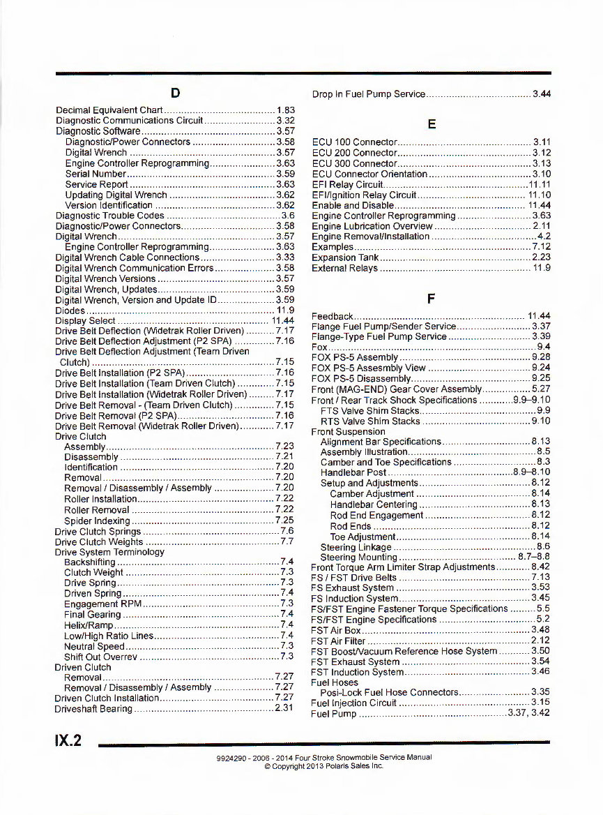
D Drop In Fuel Pump Service ... .. .... .. .. .. .. ............. . .. .... 3.44
Decimal Equivalent Chart .. .. .. .. .. ...... .... ...... .. ... .. ...... 1.83
D!agnostic Communications Circuit. .. .. ... .. .. .. .. ... .. .. .. 3.32
Diagnostic Software ... ..... ... . .. ... ............ .. ... .. .. ... ...... 3.57
E
Diagnostic/Power Connectors .... ..... .... .... .... .. .. .. .. 3.58 ECU 100 Connector .... .. ... .. .. .. .. .. .. ... .. ..... .. .. .. .... .... .. 3.11
Digital Wrench .. .. ...... .. .. .. .. .. .. .. .... .... .. .. .. .. .. .. .. .. ... 3.57 ECU 200 Connector .......... .. . .. .. .......... ...... .. .. .. .. .. .... 3.12
Engine Controller Reprogramming ..... .... ............ .. 3.63 ECU 300 Connector ...... .. ...... .. .. .. ....... .. .. ...... .. .. ...... 3. 13
Serial Number ...... .... .. . .. . .. .... . .. .... ... .. .. .. .. . .. ........ . 3.59 ECU Connector Orientation .... .. .. .. .. .... .. .. .. ... .. .... ..... 3.10
Service Report .... .. .. .. .. .. .. .. .... .. .. ... .. ... .. .... .. .. .. ..... 3.63 EFI Relay Circuit... .. ........ .. .. .. .. ... .. .. .. ......... ... .. ....... 11 .11
Updating Digital Wrench .. .. .. .. .. .... .. ... .. ... .. ... .... .. .. 3.62 EFI/Ignition Re lay Circuit... .. .. .................... .. .. .. .. .. . 11 .1 o
Version Identification .. ... ......... ........ .. .. .. .............. 3.62 Enable and Disable .. .. .... .. ...... .. .. .. ..... .. .. .... .. .. ...... . 11.44
Diagnost ic Trouble Codes .. .... .. . .. .. .. ........ .. .. .. .. ...... .. . 3.6 Engi ne Controller Reprogramming .. .. ..... .. .. ... .... .... .. 3.63
Diagnostic/Power Connectors .. ...... ......................... 3.58 Engine Lubrication Overview .......... ....... .. .. ...... .. ..... 2.11
Digital Wrench .... ....... .... . .. ......... ........... ......... .. .. .. .. 3.57 Engine Removal/Installation ..... . .. .... ... .. .. .. .... ..... ... .. .. 4.2
Engine Controller Reprogramming ............... ........ 3.63 Examples ........ .. .. ........... .. .... .................... .. ....... .. .. 7.12
Digital Wrench Cable Connections . .. ................. .. .. .. 3.33 Expansion Tank ... ............ .... . .. .. .. .... ......... .. .. .. .. ...... 2.23
Digital Wrench Communication Errors .... .. .. ........... .. 3.58 External Relays .... .. ... ........ .. .. ... ...... ..... .. ............ .... 11.9
Digital Wrench Versions .. ...... .... .. .... ...... .... .. .. .. .... ... 3.57
Digital Wrench, Updates .... .. .............. .. ... .. .... .. .. .. .. .. 3.59
Digital Wrench, Version and Update ID .. .. .. .. .. .. ..... ... 3.59 F
Diodes .. .. ............ .. ... .. .... ... .. ..... ... .......... .. ... .. .... .. .. . 11 .9
Display Select .. .. .... .. .. .. ............ .. .. .. .. .. .... .. .. .. .... .. . 11 .44
Dr!ve Belt Deflection (Widetrak Roller Driven) .......... 7.17
Drrve Belt Deflection Adjustment (P2 SPA) .......... .. .. 7.16
Drrve Belt Deflection Adjustment (Team Driven
Clutch) ...... .. .. .. . .. ...... .. ... . .. .. . ... ........ ..................... 7.15
Drive Belt Installation (P2 SPA) .. .. .. .. ............ .. .. ....... 7.16
Drive Belt Installation (Team Driven Clutch) .. .. .. .. .... . 7.15
Drive Belt Insta ll ation (Widetrak Roller Driven) .. .. .. .. . 7.17
Drive Belt Removal - (Team Driven Clutch) .. .. .......... 7.15
Drive Belt Removal (P2 SPA) ...... .. .......... .. .. .... .. .. .. .. 7.16
Drive Belt Removal (Widetrak Roller Driven) .. .. .. .. .... 7.17
Drive Clutch
Assembly ... . .. ..... ..... .. .. .. .. ... .... .. . .. . .. .. .. ..... .... ... .... 7.23
Disassembly .. .. ... .. .. .. ... .... .. ... ... ..... ... .. .. .. ......... ... 7.21
Identification ... ... .. ... .. .. .. ..... .... .. ..... .. . .. ..... ... .. .. .. .. 7.20
Removal ..... ............ .. .. .. .. .... ... ..... .. ... .... .. .. ... .. . .. .. 7.20
Removal/ Disassembly I Assembly .. .. .. ..... .... .. .... 7.20
Roller Installation .. ...... . .. ..... .. ... .... ..... .. .. .. ..... ....... 7.22
Roller Removal ...... ... .. .. .. .... .... .. .. .. .. .. .. ... ... .... ..... 7.22
Spider Indexing ...... .. .. .. .. .. ... .. .. .... ...... .. ...... .... .. ... 7.25
Drive Clutch Springs ........ .. .. .. .. . .. .. .. .. .. .... .. .. ...... ....... 7.6
Drive Clutch Weights .... .. .. .. .. .. .. .. .. .. .. .. .... ... ... .. ......... 7.7
Drive System Terminology
Backshifting . .. ...... . .. ... ... ... ... ...... ... .. ... . ... .... .. .. ..... .. 7.4
Clutch Weight .. ........ .. .. .. ..... .. .. .... .... .... ... .. .... ... .... . 7.3
Drive Spring ....... .. ... .... .. .. .. ...... .... . .. .... . .. .. .. .. .. ..... .. 7.3
Driven Sprin g ........ .. .... .. .. .. .. .. .... .... ... .. ...... . .. .. .... ... 7.4
Engagement RPM .. ..... .. ..... .. . .. .. .. ..... .. .. .. .. .. .. ... .. .. . 7.3
Final Gearing .. .. .. ...... .. .. .. .. .. .. .. .. .. ... .. .. ... .. ... .. ... .. .. . 7.4
He li x/Ramp .. .... .. ...... .. ......... .. ... ... .... .. .. .... ....... .. .. .. 7.4
Low/High Ratio Lines .. .. .. .. .. .... .. . .. .... .... .. .. ... .. ..... .. . 7.4
Neutral Speed .. .. .. .. .... . .. .... .. .. ... ... .. ... .. ... ... .. . .. .. ..... 7. 3
Sh ift Out Overrev ........ .. .. .. ...... .. .. .. .. .. .. .. .. . .. .. ........ 7.3
Driven Clutch
Removal .. ... .. ... ... ........... ... ... .......... .. ... .. .. ... .... .. .. 7.27
Removal/ Disassembly I Assembly .. .. .. .. .. ... .. .. .... 7.27
Driven Clutch Insta ll ation .. .. ...... .. .... .. .. .. .. ... .. .. .. .. .... . 7.27
Driveshaft Beari ng .. .... .. .... .. .. .. .... ....... ... .... .. ... .. .. .. .. 2.31
Feedback .. ......... .... .. ...... ......... .. . .. ..... .... .. . .. .. .. .. .. . 11.44
Flange Fuel Pump/Sender Service .. .. .. ..... .. .... ...... ... 3.37
Flange-Type Fuel Pump Service .......... .. .... .. .. .. ...... . 3.39
Fox .... ..... .............. .. ............ ............ .. .. ... .. ............. .. 9.4
FOX PS-5 Assembly .. ...... .... .. .. ........... .. .. .. .. .. .... .. ... 9.28
FOX PS-5 Assesmbly View .... .. .............. .. .. ...... .. .. .. 9.24
FOX PS-5 Disassembly .. .. .... .. .. ................ ........ .. .... 9.25
Front (MAG-END) Gear Cover Assembly .... .. .. .. .. .... . 5.27
Front/ Rear Track Shock Specifications ............ 9. 9-9 .10
FTS Valve Shim Stacks .. .. .... ...... .. .. .. ...... ..... .. ...... .. 9.9
RTS Valve Shim Stacks .. .. .. .. .. .. .. .. .... .. ... .. ... .. .. .. .. 9.10
Front Suspension
Alignment Bar Specifications .................... .. .... .. ... 8.13
Assembly Illustration .... .. .. ..... .. . .. .... .. .. ... ..... .. ... .. ... . 8.5
Camber and Toe Specifications .... ... .. .. .. .. .... .... .. .... 8.3
Handlebar Post .. .. ..... .... .. .. .. ... .. .. . .. ..... .. .. ... ... 8.9-8 .10
Setup and Adjustments .... ..... .. .... .. .. .. .. .. .. .. .... ...... 8.12
Camber Adjustment .. ......... .. .. .. .. .... ... .. ... .. .. .... . 8.14
Handlebar Centering . .. .. .... ..... ...... . .. ....... .. ..... .. 8.13
Rod End Engagement .. .. .. .... ... ... .. .. .. .. .. .. .. .... ... 8. 12
Rod Ends . .. ..... .. .. .... .... . .. .. .. .. .. ...... ..... .... ... .. .. .. 8.12
Toe Adjustment.. ........... .. ..... . .. . .. .. ...... .... ..... .. .. 8.14
Steering Linkage .. .. . .. ....... .. .. .... .. ..... .. . .. ..... .. . .. ...... 8.6
Steering Mounting .... .. .. .. .. .. .. .. ............ .. .. .. .... . 8.7-8 .8
Front To rque Arm Limiter Strap Adjustments .. .. .. ...... 8.42
FS I FST Drive Belts .. .. .. .. .. .. .... .. .. .. ........ ...... ..... .. .. . 7.13
FS Exhaust System .. ........ .. .. .. .. .. .... .. ........ .. .. .. .. .. .. . 3.53
FS Induction System ...... .. .. .... .. ...... .. .. .. ........ .. .... .. .. 3.45
FS/FST Engine Fastener Torque Specifications ......... 5.5
FS/FST Engine Specifications .... .. .. .. ........ .. .. .. .. .... .. .. 5.2
FST Air Box .. .. .. .. ...... .. .. .. .. .. .. .. .. .... ...... .. .... .. .... .. .. .. . 3.48
FST Air Fi lter .. .. .. .. ........ .. .. .. .. .. .. .... .. .. .............. .. .. .. . 2. 12
FST BoosWacuum Reference Hose System .. .. .. ..... 3.50
FST Exhaust System .. .. .. ........ .. .. .. .. .. ................. .. .. 3.54
FST Induction System . .. .. .. ..... .. . ... .. ..... ..... . .. .. .... .... . 3.46
Fuel Hoses
Posi-Lock Fuel Hose Connectors .. .... .. ...... .... .. ..... 3.35
Fuel Injection Circuit .. .. .. .. .. .. .. .... .. .. .... .. ... .. .... .... .... . 3. 15
Fuel Pump .. .. .. .. .. .... .. ........ ... .. .. .. ... .. ..... .. .. .... . 3.37, 3.42
IX.2
9924290-2006 - 2014 Four Stroke Snowmobil e Serv ice Manual
© Copyri ght 2013 Polaris Sales Inc.
You're Reading a Preview
What's Included?
Fast Download Speeds
Online & Offline Access
Access PDF Contents & Bookmarks
Full Search Facility
Print one or all pages of your manual
$31.99
Viewed 84 Times Today


Secure transaction
What's Included?
Fast Download Speeds
Online & Offline Access
Access PDF Contents & Bookmarks
Full Search Facility
Print one or all pages of your manual
$31.99
Get the most comprehensive repair, service, and technical manual for Polaris 2006-2014 Four Stroke (4-stroke) Snowmobiles. This 508-page manual covers a wide range of models, making it useful for both professional mechanics and DIY enthusiasts.
- Includes step-by-step instructions and exploded views for easy repairs and maintenance.
- Sections cover Model Specifications, Maintenance, EFI/Ignition Systems, Engine, Final Drive/Brakes, PVT System, Steering/Suspensions, Shocks, Chassis, and Electrical/Wiring Diagrams.
Print the entire manual or specific pages for quick reference. The manual is compatible with PC, Mac, tablet, and smartphone, offering convenient access to the information you need.
- Compatible with 2006-2014 Polaris Four Stroke (4-stroke) Snowmobile models, including FS Classic, FST Classic, FS Touring, FST Touring, FST Switchback, FST IQ, FST IQ LX, FS IQ Touring, FST IQ Touring, FST IQ Cruiser, FST IQ Switchback, IQ Turbo Dragon, IQ Turbo LX, Turbo Switchback, FS IQ WideTrak, Turbo IQ, Turbo IQ LX, Turbo IQ LXT, and more.


