IMPORTANT WARNING/CAUTION/NOTE Please read this manual and follow its instructions carefully. To emphasize special information, the words WARNING, CAUTION and NOTE have special meanings. Pay special attention to the messages highlighted by these signal words. WARNING: Indicates a potential hazard that could result in death or injury. CAUTION: Indicates a potential hazard that could result in vehicle damage. NOTE: Indicates special information to make maintenance easier or instructions clearer. WARNING: This service manual is intended for authorized Suzuki dealers and qualified service mechanics only. Inexperienced mechanics or mechanics without the proper tools and equipment may not be able to properly perform the services described in this manual. Improper repair may result in injury to the mechanic and may render the vehicle unsafe for the driver and passengers. WARNING: For vehicles equipped with a Supplemental Restraint (Air Bag) System: • Service on and around the air bag system components or wiring must be performed only by an authorized SUZUKI dealer. Refer to “Air Bag System Components and Wiring Location View” under “General Description” in air bag system section in order to confirm whether you are performing ser- vice on or near the air bag system components or wiring. Please observe all WARNINGS and “Ser- vice Precautions” under “On-Vehicle Service” in air bag system section before performing service on or around the air bag system components or wiring. Failure to follow WARNINGS could result in unintentional activation of the system or could render the system inoperative. Either of these two conditions may result in severe injury. • If the air bag system and another vehicle system both need repair, Suzuki recommends that the air bag system be repaired first, to help avoid unintended air bag system activation. • Do not modify the steering wheel, instrument panel or any other air bag system component (on or around air bag system components or wiring). Modifications can adversely affect air bag system performance and lead to injury. • If the vehicle will be exposed to temperatures over 93°C (200°F) (for example, during a paint baking process), remove the air bag system components (air bag (inflator) modules, SDM and/or seat belt with pretensioner) beforehand to avoid component damage or unintended activation.
TABLE OF CONTENTS GENERAL INFORMATION ENGINE 0A 6 General Information 0A General Information and Diagnosis 6 0B 6A1 Maintenance and Lubrication 0B Engine Mechanical 6A1 6B HEATING AND AIR CONDITIONING Engine Cooling 6B 1A 6C Heater and Ventilation 1A Engine Fuel 6C 1B 6E1 Air Conditioning 1B Engine and Emission Control System 6E1 6F1 STEERING, SUSPENSION, WHEELS AND TIRES Ignition System 6F1 3 6G Cranking System 6G 3A 6H Steering, Suspension, Wheels and Tires 3 Charging System 6H 3B 6K Front End Alignment 3A Exhaust System 6K 3B1 6B Manual Rack and Pinion 3B TRANSMISSION, CLUTCH AND DIFFERENTIAL 3C 7A Power Steering System 3B1 3D 7B Steering Wheel and Column 3C Manual Transmission 7A 3E 7C Front Suspension 3D Automatic Transmission 7B 3F 7D Rear Suspension 3E Clutch 7C 7F Wheels and Tires 3F Transfer 7D 4A DRIVE SHAFT AND PROPELLER SHAFT Differential (Rear)(4WD) 7F 4B 8 Front Drive Shaft 4A ELECTRICAL SYSTEM 8A Propeller Shaft 4B Body Electrical System 8 5 8G BRAKE SYSTEM Wiring Diagram 8A 5E Brakes 5 Immobilizer Control System (if equipped) 8G 9 Antilock Brake System 5E BODY SERVICE 9 RESTRAINT SYSTEM 10 Restraint System 10 10B Air Bag System (if equipped) 10B NOTE: The screen toned Section 8A is in Wiring Diagram Manual mentioned in FOREWORD of this manual.
GENERAL INFORMATION 0A-1 0A 6F2 6G 6H 6K 7A 7A1 7B1 7C1 7D 7E 7F 8A 8B 8C 8D 8E 9 10 10A 10B SECTION 0A GENERAL INFORMATION CONTENTS HOW TO USE THIS MANUAL .........................0A-2 PRECAUTIONS ................................................ 0A-3 PRECAUTION FOR VEHICLES EQUIPPED WITH A SUPPLEMENTAL RESTRAINT (AIR BAG) SYSTEM ..................................... 0A-3 DIAGNOSIS .............................................. 0A-3 SERVICING AND HANDLING .................. 0A-4 GENERAL PRECAUTIONS .......................... 0A-6 PRECAUTIONS FOR CATALYTIC CONVERTER................................................ 0A-9 PRECAUTION FOR INSTALLING MOBILE COMMUNICATION EQUIPMENT ................. 0A-9 PRECAUTION IN SERVICING FULL-TIME 4WD VEHICLE ............................................ 0A-10 PRECAUTIONS FOR ELECTRICAL CIRCUIT SERVICE ..................................... 0A-11 ELECTRICAL CIRCUIT INSPECTION PROCEDURE ............................................. 0A-13 OPEN CIRCUIT CHECK ......................... 0A-13 CONTINUITY CHECK ............................. 0A-14 VOLTAGE CHECK .................................. 0A-15 SHORT CIRCUIT CHECK (WIRE HARNESS TO GROUND)....................... 0A-16 INTERMITTENT AND POOR CONNECTION ............................................ 0A-16 IDENTIFICATION INFORMATION ................. 0A-18 VEHICLE IDENTIFICATION NUMBER ...... 0A-18 ENGINE IDENTIFICATION NUMBER ........ 0A-18 TRANSMISSION IDENTIFICATION NUMBER .................................................... 0A-18 WARNING, CAUTION AND INFORMATION LABELS.......................................................... 0A-19 VEHICLE LIFTING POINTS ........................... 0A-20 ABBREVIATIONS AND SYMBOLS MAY BE USED IN THIS MANUAL.......................... 0A-22 FASTENER INFORMATION .......................... 0A-25 METRIC FASTENERS................................ 0A-25 FASTENER STRENGTH IDENTIFICATION ....................................... 0A-25 STANDARD TIGHTENING TORQUE......... 0A-25
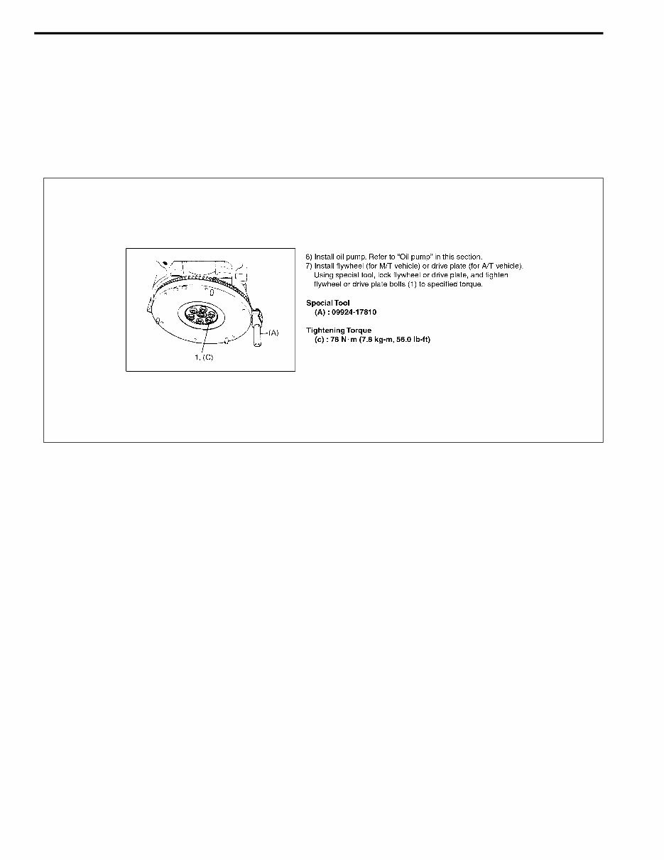
0A-2 GENERAL INFORMATION HOW TO USE THIS MANUAL 1) There is a “TABLE OF CONTENTS” on the third page of this manual, whereby you can easily find the sec- tion that offers the information you need. Also, there is a CONTENTS on the first page of each section, where the main items in that section are listed. 2) Each section of this manual has its own pagination. It is indicated at the top of each page along with the Sec- tion name. 3) The special tool usage and torque specification are given as shown in the figure. 4) A number of abbreviations and symbols are used in the text.For their full explanations, refer to “ABBREVIA- TIONS AND SYMBOLS MAY BE USED IN THIS MANUAL” in this section. 5) The SI, metric and foot-pound systems are used as units in this manual. 6) “DIAGNOSIS” are included in each section as necessary. 7) At the end of each section, there are descriptions of “SPECIAL TOOL”, “REQUIRED SERVICE MATERIAL” and “TIGHTENING TORQUE SPECIFICATION” that should be used for the servicing work described in that section.
GENERAL INFORMATION 0A-3 PRECAUTIONS PRECAUTION FOR VEHICLES EQUIPPED WITH A SUPPLEMENTAL RESTRAINT (AIR BAG) SYSTEM DIAGNOSIS • When troubleshooting air bag system, be sure to follow “DIAGNOSIS” in SECTION 10B. Bypassing these proce- dures may result in extended diagnostic time, incorrect diag- nosis, and incorrect parts replacement. • Never use electrical test equipment other than that specified in this manual. WARNING: • The configuration of air bag system parts are as shown in the figure. When it is necessary to service (remove, reinstall and inspect) these parts, be sure to follow procedures described in SECTION 10B. Failure to fol- low proper procedures could result in possible air bag system activation, personal injury, damage to parts or air bag system being unable to activate when neces- sary. • If the air bag system and another vehicle system both need repair, SUZUKI recommends that the air bag sys- tem be repaired first, to help avoid unintended air bag system activation. • Do not modify the steering wheel, dashboard, or any other air bag system components. Modifications can adversely affect air bag system performance and lead to injury. • If the vehicle will be exposed to temperatures over 93°C (200°F) (for example, during a paint baking pro- cess), remove the air bag system components before- hand to avoid component damage or unintended air bag system activation. 1. Air bag wire harness 4. Seat belt pretensioner 2. Passenger air bag (inflator) module 5. Contact coil 3. SDM 6. Driver air bag (inflator) module 3 4 4 6 1 5 2 WARNING: Never attempt to measure the resistance of the air bag (inflator) modules (driver and passenger) and seat belt pretensioners (driver and passenger). It is very danger- ous as the electric current from the tester may deploy the air bag or activate the pretensioner.
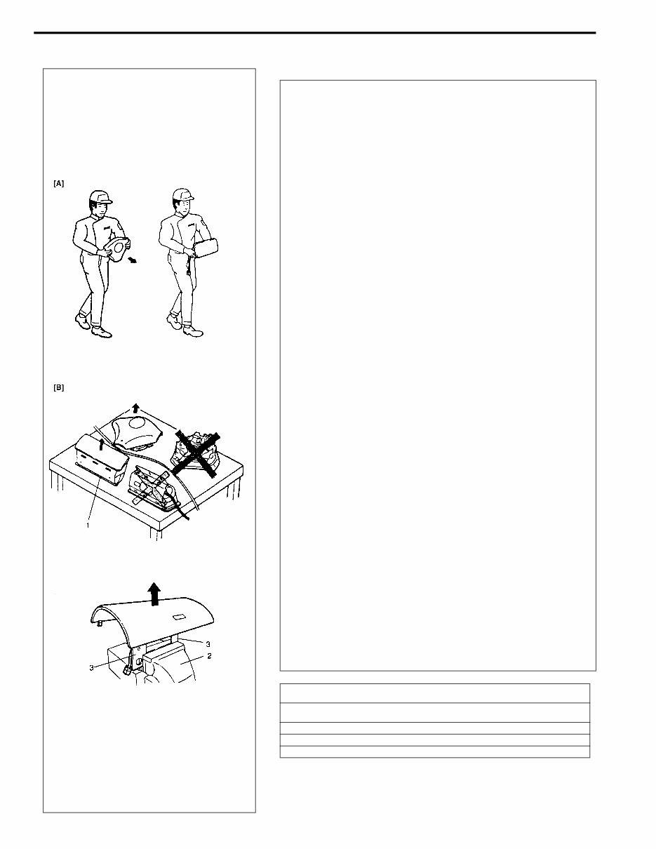
0A-4 GENERAL INFORMATION SERVICING AND HANDLING WARNING: Many of service procedures require disconnection of “AIR BAG” fuse and all air bag (inflator) module(s) from initiator circuit to avoid an accidental deployment. Driver and Passenger Air Bag (Inflator) Modules • For handling and storage of a live air bag (inflator) module, select a place where the ambient temperature below 65°C (150°F), without high humidity and away from electric noise. • When carrying a live air bag (inflator) module, make sure the bag opening is pointed away from you. In case of an accidental deployment, the bag will then deploy with minimal chance of injury. Never carry the air bag (inflator) module by the wires or connector on the underside of the module. When placing a live air bag (inflator) module on a bench or other surface, always face the bag up, away from the surface. As the live passenger air bag (inflator) module must be placed with its bag (trim cover) facing up, place it on the work- bench with a slit or use the workbench vise to hold it securely at its lower mounting bracket. This is neces- sary so that a free space is provided to allow the air bag to expand in the unlikely event of accidental deployment. Otherwise, personal injury may result. • Never dispose of live (undeployed) air bag (inflator) modules (driver and passenger). If disposal is neces- sary, be sure to deploy them according to deployment procedures described in SECTION 10B before dis- posal. • The air bag (inflator) module immediately after deploy- ment is very hot. Wait for at least half an hour to cool it off before proceeding the work. • After an air bag (inflator) module has been deployed, the surface of the air bag may contain a powdery resi- due. This powder consists primarily of cornstarch (used to lubricate the bag as it inflates) and by-prod- ucts of the chemical reaction. As with many service procedures, gloves and safety glasses should be worn. [A] : ALWAYS CARRY AIR BAG (INFLATOR) MODULE WITH TRIM COVER (AIR BAG OPENING) AWAY FROM BODY. [B] : ALWAYS PLACE AIR BAG (INFLATOR) MODULE ON WORKBENCH WITH TRIM COVER (AIR BAG OPENING) UP, AWAY FROM LOOSE OBJECTS. 1. Slit on workbench 2. Workbench vise 3. Lower mounting bracket
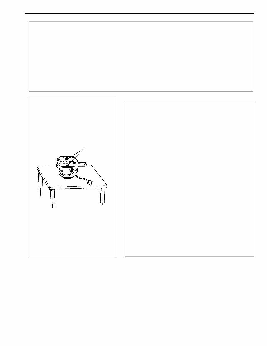
GENERAL INFORMATION 0A-5 • Even when the accident was light enough not to cause air bags to activate, be sure to inspect sys- tem parts and other related parts according to instructions under “REPAIR AND INSPECTION REQUIRED AFTER AN ACCIDENT” in SECTION 10B. • When servicing parts other than air bag system, if shocks may be applied to air bag system compo- nent parts, remove those parts beforehand. • When handling the air bag (inflator) modules (driver and passenger), seat belt pretensioners (driver and passenger) or SDM, be careful not to drop it or apply an impact to it. If an excessive impact was applied, never attempt disassembly or repair but replace it with a new one. • When grease, cleaning agent, oil, water, etc. has got onto air bag (inflator) modules (driver and pas- senger) or seat belt pretensioners (drive and passenger), wipe off immediately with a dry cloth. WARNING: SDM • For handling and storage of a SDM, select a place where the ambient temperature below 65°C (150°F), without high humidity and away from electric noise. • During service procedures, be very careful when handling a Sensing and Diagnostic Module (SDM). Never strike or jar the SDM. • Never power up the air bag system when the SDM is not rigidly attached to the vehicle. All SDM and mounting bracket fasteners must be carefully torqued and the arrow must be pointing toward the front of the vehicle to ensure proper operation of the air bag system. The SDM could be activated when powered while not rigidly attached to the vehicle which could cause deployment and result in personal injury. WARNING: Driver and Passenger Seat Belt Pretensioners (If equipped) • For handling and storage of a live seat belt preten- sioner, select a place where the ambient temperature below 65°C (150°F), without high humidity and away from electric noise. • Never carry seat belt pretensioner by wire or connec- tor of pretensioner. When placing a live seat belt pre- tensioner on the workbench or some place like that, be sure not to lay it with its exhaust hole (1) provided side facing down. It is also prohibited to put something on its face with an exhaust hole or to put a seat belt pre- tensioner on top of another. Otherwise, personal injury may result. • Never dispose of live (inactivated) seat belt pretension- ers (drive and passenger). If disposal is necessary, be sure to activate them according to activation proce- dures described in SECTION 10B before disposal. • The seat belt pretensioner immediately after activation is very hot. Wait for at least half an hour to cool it off before proceeding the work. • With many service procedures, gloves and safety glasses should be worn to prevent any possible irrita- tion of the skin or eyes.
0A-6 GENERAL INFORMATION • Air bag wire harness can be identified easily as it is covered with a yellow protection tube. Be very careful when handling it. • When an open in air bag wire harness, damaged wire harness, connector or terminal is found, replace wire harness, connectors and terminals as an assembly. • Do not apply power to the air bag system unless all components are connected or a diagnostic chart requests it, as this will set a diagnostic trouble code. • Never use air bag system component parts from another vehicle. • When using electric welding, be sure to temporarily disable air bag system referring to “DISABLING AIR BAG SYSTEM” in Section 10B. • Never expose air bag system component parts directly to hot air (drying or baking the vehicle after painting) or flames. • WARNING/CAUTION labels are attached on each part of air bag system components. Be sure to fol- low the instructions. • After vehicle is completely repaired, perform “AIR BAG DIAGNOSTIC SYSTEM CHECK” in SECTION 10B. GENERAL PRECAUTIONS The WARNING and CAUTION below describe some general precautions that you should observe when servic- ing a vehicle. These general precautions apply to many of the service procedures described in this manual, and they will not necessarily be repeated with each procedure to which they apply. WARNING: • Whenever raising a vehicle for service, be sure to follow the instructions under “VEHICLE LIFTING POINTS” in this section. • When it is necessary to do service work with the engine running, make sure that the parking brake is set fully and the transmission is in Neutral (for manual transmission vehicles) or Park (for auto- matic transmission vehicles), Keep hands, hair, clothing, tools, etc. away from the fan and belts when the engine is running. • When it is necessary to run the engine indoors, make sure that the exhaust gas is forced outdoors. • Do not perform service work in areas where combustible materials can come in contact with a hot exhaust system. When working with toxic or flammable materials (such as gasoline and refriger- ant), make sure that the area you work in is well-ventilated. • To avoid getting burned, keep away from hot metal parts such as the radiator, exhaust manifold, tail pipe, muffler, etc. • New and used engine oil can be hazardous. Children and pets may be harmed by swallowing new or used oil. Keep new and used oil and used engine oil filters away from children and pets. Continuous contact with used engine oil has been found to cause [skin] cancer in laboratory ani- mals. Brief contact with used oil may irritate skin. To minimize your exposure to used engine oil, wear a long-sleeve shirt and moisture-proof gloves (such as dish washing gloves) when changing engine oil. If engine oil contacts your skin, wash thoroughly with soap and water. Launder any clothing or rags if wet with oil, recycle or properly dispose of used oil and filters. • Make sure the bonnet is fully closed and latched before driving. If it is not, it can fly up unexpect- edly during driving, obstructing your view and resulting in an accident.
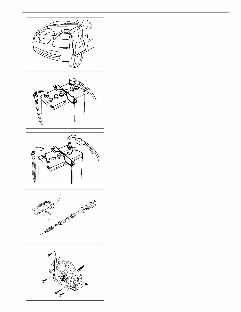
GENERAL INFORMATION 0A-7 • Before starting any service work, cover fenders, seats and any other parts that are likely to get scratched or stained during servicing. Also, be aware that what you wear (e.g, buttons) may cause damage to the vehicle’s finish. • When performing service to electrical parts that does not require use of battery power, disconnect the nega- tive cable of the battery. • When removing the battery, be sure to disconnect the negative cable first and then the positive cable. When reconnecting the battery, connect the positive cable first and then the negative cable, and replace the terminal cover. • When removing parts that are to be reused, be sure to keep them arranged in an orderly manner so that they may be reinstalled in the proper order and position. • Whenever you use oil seals, gaskets, packing, O-rings, locking washers, split pins, self-locking nuts, and cer- tain other parts as specified, be sure to use new ones. Also, before installing new gaskets, packing, etc., be sure to remove any residual material from the mating surfaces.
This workshop manual is a comprehensive source of maintenance and repair procedures for the Suzuki Ignis RG413 RG415. It provides step-by-step instructions, detailed diagrams, and illustrations to guide both professional mechanics and DIY enthusiasts through servicing, maintenance, and repairs. The manual covers a wide range of topics including general information, heating and air conditioning, steering, suspension, wheels and tires, drive shaft and propeller shaft, brake system, engine, transmission, clutch, and differential, electrical system, body service, restraint system, airbag system, wiring diagrams, and more.
The applicable models covered by this manual include the Suzuki Ignis RG413 RG415, with specific coverage for the RG413 Service Manual 2000, IGNIS (RG413) Supplementary Service Manual 2002, IGNIS (RG413/RG415) Supplementary Service Manual 2003, and IGNIS (RG413/RG415) Wiring Diagram Manual.
Upon purchase, you will receive the manual instantly without any shipping costs, as it is available in file format for immediate access. The manual is compatible with all versions of Windows and Mac, and it can be printed for ease of use. The language of the manual is English, and it requires Adobe Reader and Win to access the content.