1 WORKSHOP REPAIR MANUAL GENERAL INFORMATION 0 HEATING AND VENTILATION BRAKES MAIN INDEX ISUZU CONTENTS WHEELS AND TYRES 4 5 BODY 8 SECURITY 11 SUSPENSION 3 STEERING 2 AXLE FRAME AND CAB ENGINE 6 TRANSMISSION 7 MY 2007 RESTRAINTS 9 CAB 10 BACK TO FRONT PAGE KB P190 ISUZU KB P190 2007
GENERAL INFORMATION 0-1 SECTION 0 GENERAL INFORMATION TABLE OF CONTENTS PAGE Section 0A General Informantion ...........................................................................................3 Section 0B Maintainance and Lubrication............................................................................... 19 TO MODEL INDEX BACK TO MAIN INDEX ISUZU KB P190 2007
SECTION 0A GENERAL INFORMATION TABLE OF CONTENTS GENERAL INFORMATION 0A-1 General Repair Instructions ........................................................................................... 0A- 2 PAGE Notes on the Format of this Manual............................................................................... 0A- 3 Identification .................................................................................................................... 0A- 6 Lifting Instructions .......................................................................................................... 0A- 7 Conversion Table ............................................................................................................ 0A- 9 BACK TO CHAPTER INDEX TO MODEL INDEX ISUZU KB P190 2007
0A-2 GENERAL INFORMATION GENERAL REPAIR INSTRUCTIONS 1.Park the vehicle on level ground and chock the front or rear wheels before lifting the vehicle. 2.Raise the vehicle with a jack set against the axle or the frame. 3.Support the vehicle on chassis stands. 4.Use covers on the vehicle body, seats, and floor to prevent damage and/or contamination. 5.Disconnect the grounding cable from the battery before performing service operations. This will prevent cable damage or burning due to short circuiting. 6.Handle brake fluid and antifreeze solution with great care. Spilling these liquids on painted surfaces will damage the paint. 7.The use of the proper tool(s) and special tool(s) where specified is essential to efficient, reliable, and safe service operations. 8.Always use genuine ISUZU replacement parts. 9.Discard used cotter pins, gaskets, O-rings, oil seals, lock washers, and self-locking nuts at disassembly. Normal function of these parts cannot be guaranteed if they are reused. 10.Prepare new cotter pins, gaskets, O-rings, oil seals, lock washers, and self-locking nuts for installation. 11.Keep the disassembled parts neatly in groups. This will facilitate smooth and correct reassembly. 12.Keep fixing nuts and bolts separate. Fixing nuts and bolts vary in hardness and design according to installation position. 13.Clean all parts before inspection or reassembly. 14.Clean the oil ports and other openings with compressed air to make certain that they are free from dirt and obstructions. 15.Lubricate the rotating and sliding faces of all moving parts with oil or grease before installation. 16.Use the recommended liquid gasket to prevent leakage. 17.Carefully observe all nut and bolt torque specifications. 18.When removing or replacing parts that require refrigerant to the discharged from the air conditioning system, be sure to use the Vehicle Refrigerant Recovery and Recycling Equipment (VRRRE) to recover and recycle R134a, to promote the aim of the protection of the ozone layer covering the earth. 19.Check and recheck your work. No service operation is complete until you have done this. BACK TO CHAPTER INDEX TO MODEL INDEX ISUZU KB P190 2007
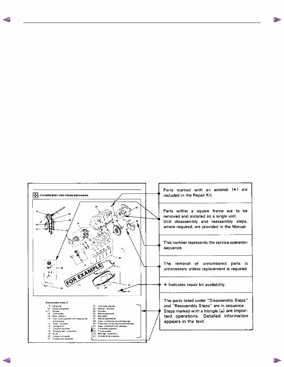
GENERAL INFORMATION 0A-3 NOTES ON THE FORMAT OF THIS MANUAL 1. Find the applicable section by referring to the index at the front of the Workshop Manual binder. 2. The following technical service information is included in this Section: • Identification • Maintenance schedules • Recommended Iubricants • Recommended fuels • Oil viscosity charts 3. Individual sections of this Workshop Manual are divided into the following categories: • Main data and specifications • Torque specifications • Recommended liquid gasket • Loctite application procedure • Servicing • Removal and installation • Disassembly • Inspection and repair • Reassembly • Troubleshooting 4. Each "Major Components" page of this Workshop Manual has an exploded view of the applicable area. A brief explanation of the notation used follows: BACK TO CHAPTER INDEX TO MODEL INDEX ISUZU KB P190 2007
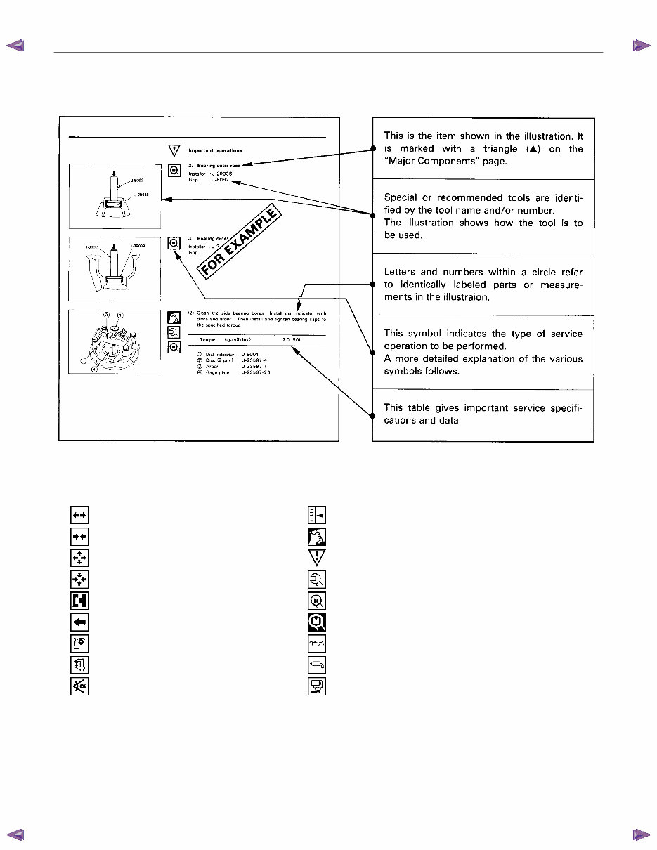
0A-4 GENERAL INFORMATION 5. Below is a sample of the Workshop Manual text following the " Major Components " page. A brief explanation of the notation used follows: 6. The following symbols appear throughout the Workshop Manual. They tell you at a glance the type of service operation to perform. ........ Removal ........ Adjustment ........ Installation ........ Cleaning ........ Disassembly ........ Important operation requiring extra care ........ Reassembly ........ Specified torque ........ Alignment ........ ISUZU special tool(s) required or recommended ........ Directional indication ........ Other special tool(s) required or recommended ........ Inspection ........ Lubrication (Oil) ........ Measurement ........ Lubrication (Grease) ........ Torque angle method ........ Liquid gasket application BACK TO CHAPTER INDEX TO MODEL INDEX ISUZU KB P190 2007
GENERAL INFORMATION 0A-5 7. Measurement criteria are defined by the terms "standard" and "limit". A measurement falling within the "standard" range indicates that the applicable part or parts are serviceable. "Limit" is an absolute value. A measurement falling outside the "limit" indicates that the applicable part or parts must be repaired or replaced. 8. Components and parts are listed in the singular form throughout the Workshop Manual. 9. The following directional criteria are used throughout the Workshop Manual: Front: The cooling fan side of the engine. Right: The right-hand side of the engine viewed from the flywheel. Left: The left-hand side of the engine viewed from the flywheel. Rear: The flywheel side of the engine. Cylinder numbers are counted from the front of the engine towards the rear. The engine's rotation is clockwise viewed from the front of the engine. BACK TO CHAPTER INDEX TO MODEL INDEX ISUZU KB P190 2007
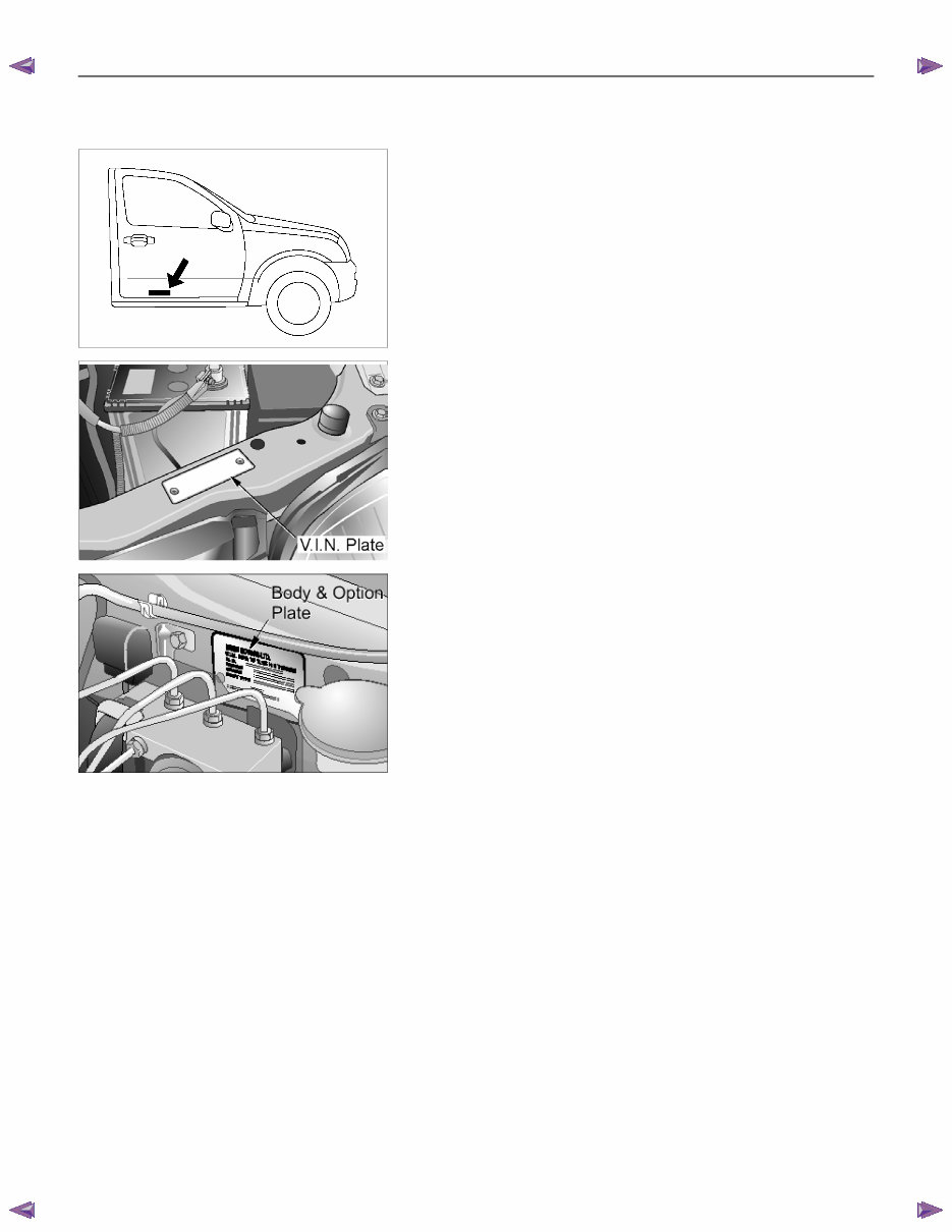
0A-6 GENERAL INFORMATION IDENTIFICATION CHASSIS NUMBER The chassis number is stamped on the right-hand side of the chassis side member under the right door. RTW50ASH000201 VEHICLE IDENTIFICATION PLATE The vehicle identification plate is attached to the upper face of the radiator sill in the engine compartment. BODY AND OPTION IDENTIFICATION PLATE The body and option plate shows body style, body serial number, paint and trim colour combination, paint number, engine transmissions, axle ratio options and built date. The built date is defined as 'the date of manufacture' by the calendar month and year in which the body shell and power train sub-assemblies are co-joined or moved from the production line. BACK TO CHAPTER INDEX TO MODEL INDEX ISUZU KB P190 2007
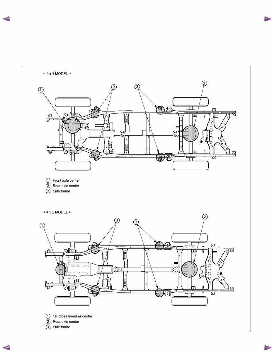
GENERAL INFORMATION 0A-7 LIFTING INSTRUCTIONS If a lifting device other than the original jack is used, it is most important that the device be applied only to the correct lifting points. (See the illustration.) Raising the vehicle from any other point may result in serious damage. Lifting Points and Supportable Point-Locations RTW50AXF000201 BACK TO CHAPTER INDEX TO MODEL INDEX ISUZU KB P190 2007
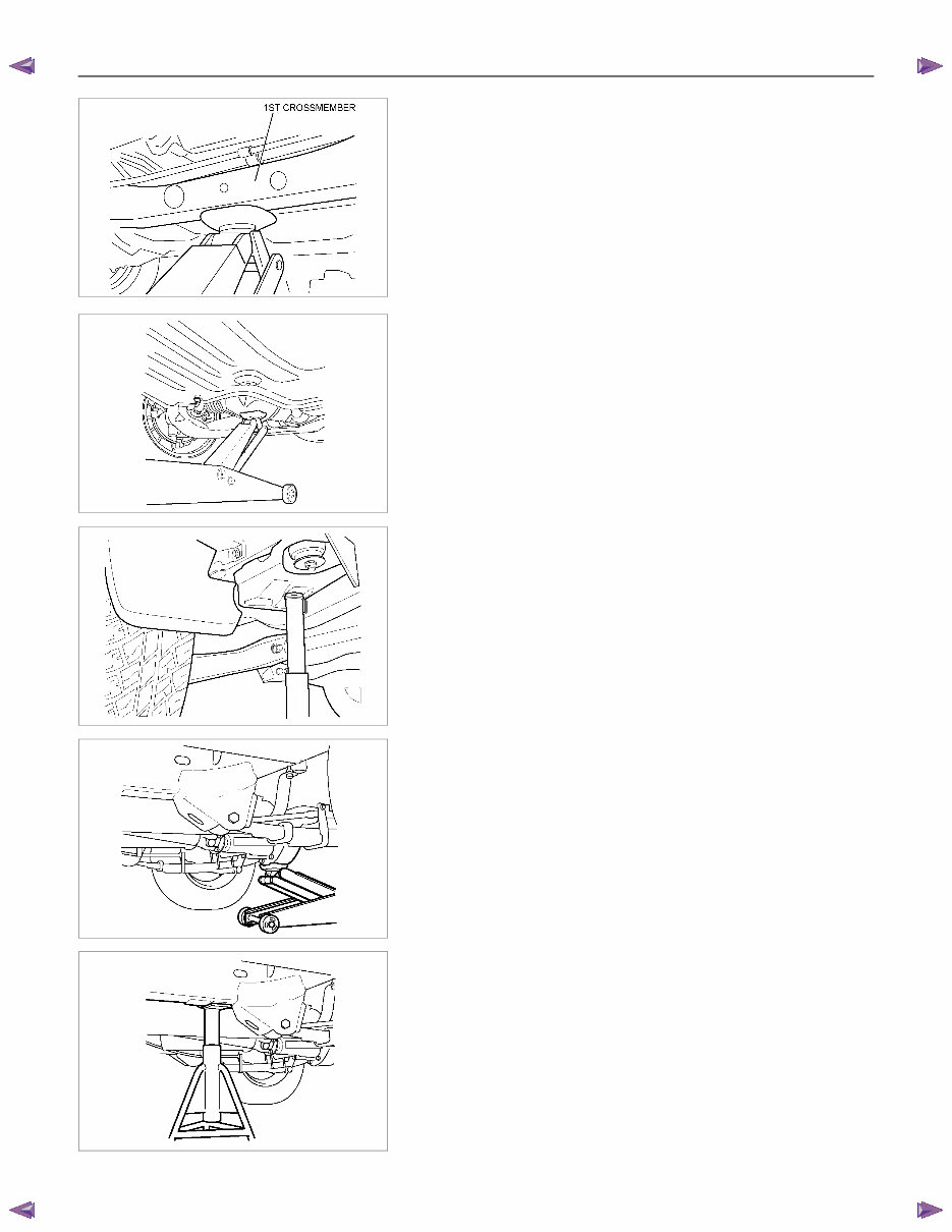
0A-8 GENERAL INFORMATION RUW50ASH000101 LIFTING POINT; FRONT 4×2 model • When using floor jack, lift the center of 1st cross member. RTW60ASH000101 4×4 model • When using floor jack, lift the center of front axle case. RTW60ASH000201 SUPPORTABLE POINT; FRONT • Position the chassis stands at the bottom of the frame side member, backward of front wheel. RTW30ASH000101 LIFTING POINT; REAR • When using floor jack, lift the center of rear axle case. RTW30ASH000201 SUPPORTABLE POINT; REAR • Position the chassis stands at the bottom of the frame side member, forward of the rear wheel. BACK TO CHAPTER INDEX TO MODEL INDEX ISUZU KB P190 2007
The 2012 Isuzu D-Max OEM Service & Repair Manual is a complete guide tailored for both professional mechanics and DIY enthusiasts. It provides step-by-step instructions, detailed illustrations, and clear explanations covering everything from routine maintenance tasks to complex repairs, including the engine, transmission, electrical system, suspension, and brakes.
Designed specifically for the 2012 Isuzu D-Max model, this manual offers accurate and reliable information—the same trusted resource used by Isuzu technicians and professionals around the globe.
Key features of the 2012 Isuzu D-Max OEM Service & Repair Manual include:
Comprehensive coverage of all aspects of maintenance and repair
Clear and detailed instructions
Illustrations and diagrams for better understanding
Accurate and reliable information
Trusted by professionals worldwide
Whether you are performing a simple oil change or undertaking a complex repair, the 2012 Isuzu D-Max OEM Service & Repair Manual is your essential resource for dependable and precise guidance.