Contents Example of wiring diagram ................................................................... 2 Component wiring diagram index ....................................................... 5 Component wiring diagrams ................................................................ 8 Illustrations index ................................................................................ 76 Illustrations ........................................................................................... 77 Fuses ................................................................................................... 137 Relays ................................................................................................. 139 Wiring harness illustration index ..................................................... 141 Earth connections ............................................................................. 144 List of earth connections ................................................................... 146 List of connectors ............................................................................. 147 List of components ........................................................................... 154 Abbreviations ..................................................................................... 160 Cable colour code ............................................................................. 161 Feedback 1
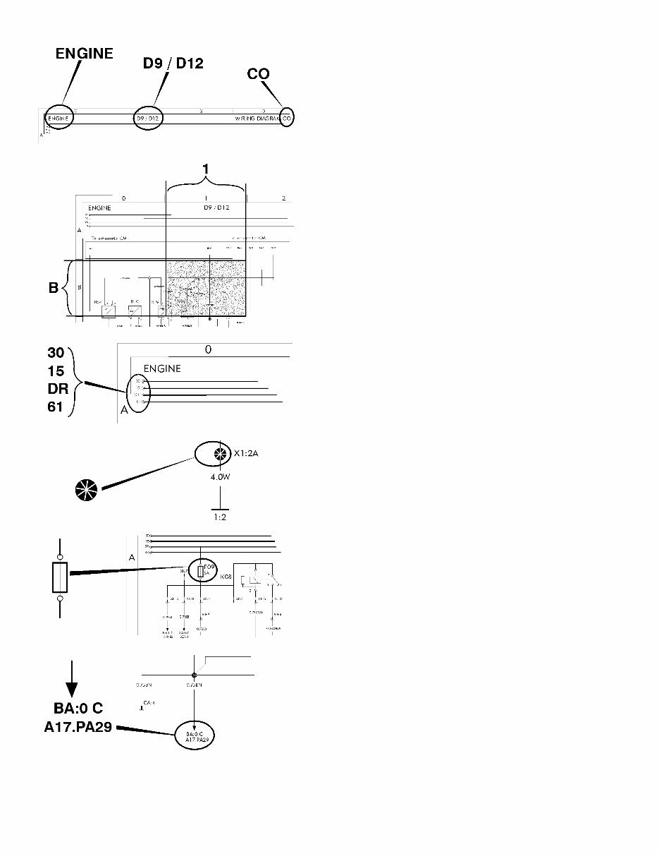
Example of wiring diagram Component wiring diagram title, variant/subtitle and sym- bol. Coordinates (B 1). 30 Voltage battery, kl.30. 15 Voltage with starter key in drive position, kl.15. DR Voltage with starter key in drive position, preheat po- sition and start position, kl.DR. 61 Voltage when alternator charges, kl.61. Splice. Fuse. Reference arrow, for diagram BA, coordinates 0 C, com- ponent A17, connector PA pin 29. 2
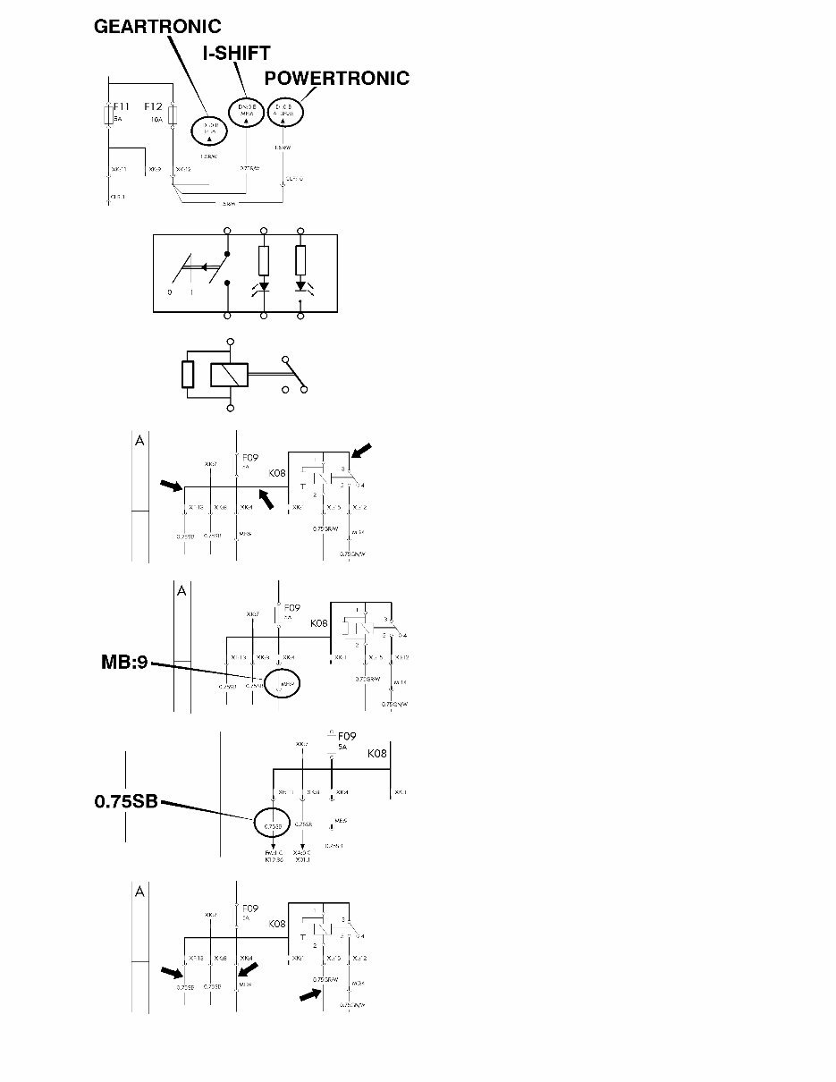
The maximum of variants are drawn, think about that all wires and components are not standard for all markets or vehicle models. Switch. Relay. Conductor on circuit card. Connector MB terminal 9. Wire area and colour. Thin lines, wires. 3
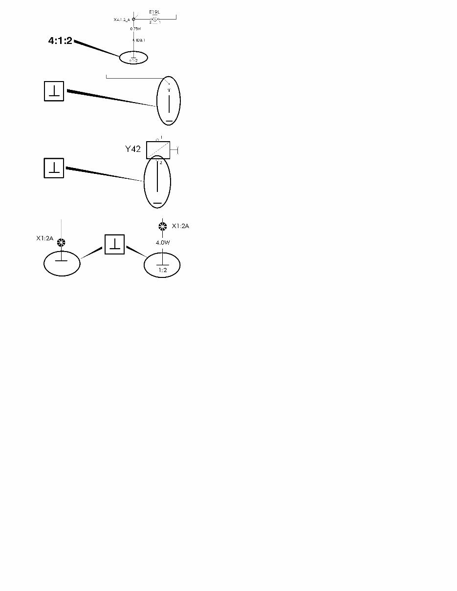
Earth connection point 4, earth connection 1 and wire 2. Earth connection to circuit card. Earth connection without wire. Same splice can be drawn on several diagrams. The wire from the splice to the earth connection point will only be drawn and coded on one diagram. On the other diagrams will only the earth connection point be written besides the splice. 4
Component wiring diagram index AA Power supply, starting system ......................................................................................... page 8 AE ADR, main switch ............................................................................................................ page 9 BA Vehicle ECU .................................................................................................................... page 10 BI Instrument cluster ............................................................................................................ page 11 BM Tachograph in dash ......................................................................................................... page 12 BN Tachograph in shelf ......................................................................................................... page 13 BU Dynafleet ......................................................................................................................... page 14 CM Engine interface ............................................................................................................... page 15 CO Engine (D9/D12) .............................................................................................................. page 16 CP ISX functions, 12V trailer ABS converter (AUS only) ..................................................... page 17 CS Engine ISX (AUS only) .................................................................................................... page 18 CU Fuel filter water drain ....................................................................................................... page 19 DB Gear selector ECU .......................................................................................................... page 20 DE Geartronic automatic gearshift ........................................................................................ page 21 DI Powertronic ...................................................................................................................... page 22 DM Retarder manual gearshift ............................................................................................... page 23 DN I-shift ................................................................................................................................ page 24 DQ Power take off .................................................................................................................. page 25 DU Diff-lock ............................................................................................................................ page 26 EC Trailer ABS/EBS supply ................................................................................................... page 27 EE ABS basic, D-version ...................................................................................................... page 28 EI ABS/ASR D-version ......................................................................................................... page 29 EM EBS ECU ......................................................................................................................... page 30 EN EBS modulators .............................................................................................................. page 31 EQ ESP ................................................................................................................................. page 32 FA Air-suspension ................................................................................................................ page 33 FG Load indikator .................................................................................................................. page 34 FK Bogie lift A-ride ................................................................................................................ page 35 FM Axle lock, self steered axle ............................................................................................. page 36 FP Hydraulic steered axle ..................................................................................................... page 37 FQ Air dryer ........................................................................................................................... page 38 FU Central lubrication system ............................................................................................... page 39 GA LCM head lights .............................................................................................................. page 40 5
GB LCM trailer, HL-HID ......................................................................................................... page 41 GC LCM rear lights ................................................................................................................ page 42 GK Trailer connections (AUS only) ........................................................................................ page 43 GM Wiper, washer .................................................................................................................. page 44 GQ Horn ................................................................................................................................. page 45 GU Headlights adjust ............................................................................................................. page 46 HG Climate unit, CU,-BAS,-MCC,-ECC ................................................................................. page 47 HI Air heater ......................................................................................................................... page 48 HM Water heater .................................................................................................................... page 49 HP Short stop cabheater ....................................................................................................... page 50 HY Climat unit, CU,-HEAT,-ACMAN,-ACAUT . ....................................................................... page 51 IA El. heated/adj. seat ......................................................................................................... page 52 IE El. heat/adj. mirrors, El. window winders ........................................................................ page 53 IF Foldable mirror bracket .................................................................................................... page 54 IH Interior light ...................................................................................................................... page 55 IM Central locking, immobiliser ............................................................................................ page 56 IQ El. sunroof, cig. lighter, refrigerator ................................................................................. page 57 IR 12V power supply ............................................................................................................ page 58 IS SWM, SRS. Air-bag ......................................................................................................... page 59 IU Radio ............................................................................................................................... page 60 IX Intergrated telephone ...................................................................................................... page 61 IZ Backup camera ................................................................................................................ page 62 KA Cab tilt ............................................................................................................................. page 63 KE Load light, 5:th wheel lamp ............................................................................................. page 64 KI Light sign ......................................................................................................................... page 65 KM Beacon warning light ....................................................................................................... page 66 ME Extra fuse block, key switch relay ................................................................................... page 67 NA Body builder (BB), auxsw-6 and swapbody .................................................................... page 68 NC Body builder (BB), ELCE-CK, BBM, PTO2 ..................................................................... page 69 NI Extra spotlamps front/roof, max 4x70W .......................................................................... page 70 NK Burglar alarm ................................................................................................................... page 71 NR Body builder (BB), tipper tractor ”HYDRKIT” .................................................................. page 72 NU Body builder (BB), DUAL-SPEED ................................................................................... page 73 XA Bus J1708/J1587 ............................................................................................................. page 74 XB Bus J1939 ....................................................................................................................... page 75 6
Component wiring diagrams 7
T3016280 8
You're Reading a Preview
What's Included?
Lifetime Access
Fast Download Speeds
Online & Offline Access
Access PDF Contents & Bookmarks
Full Search Facility
Print one or all pages of your manual
$28.99
August 2002 Volvo FM9 FM12 FH12 VERSION2 Truck Wiring Diagram Service & Repair Manual
The Volvo FM9 FM12 FH12 VERSION2 Truck Wiring Diagram Service Manual is a highly detailed manual with comprehensive wiring diagrams and illustrations. It provides step-by-step instructions for both DIY enthusiasts and experienced mechanics. The manual covers a wide range of topics including wiring diagrams, component wiring diagrams, illustrations, fuses, relays, wiring harness illustrations, earth connections, connectors, components, abbreviations, cable color code, feedback, and more.
This manual comes in a format compatible with all versions of Windows and Mac operating systems. It is in English and requires Adobe Reader and Win to access. With instant access, you can avoid waiting and start using the manual immediately. This manual is a valuable resource for keeping your Volvo FM9 FM12 FH12 VERSION2 Truck in proper working condition.
Reviews
Q&A
Recently Viewed
5,521,897Happy Clients
2,594,462eManuals
1,120,453Trusted Sellers
15Years in Business
Price:
Actual Price:
August 2002 Volvo FM9 FM12 FH12 VERSION2 Truck Wiring Diagram Service & Repair Manual

")