

volvo fl7 fl10 wiring diagram manual
What's Included?
Fast Download Speeds
Online & Offline Access
Access PDF Contents & Bookmarks
Full Search Facility
Print one or all pages of your manual

Service Manual
Trucks
Group 37
Wiring Diagram
FL7, FL10 RHD
CHID A246776–
CHID C752586–
TSP23761/1

Foreword
The descriptions and service procedures contained in this manual are based on design
and method studies placed up to May 1996.
The products are under continuous development. Vehicles and components produced
after the above date may therefore have different specifications and repair methods.
When this is judged to have a significant bearing on this manual, supplementary service
bulletins will be issued to cover the changes.
The new edition of this manual will update the changes.
In service procedures where the title incorporates an operation number, this is a
reference to V.S.T. (Volvo Standard Times).
Service procedures which do not include an operation number in the title are for general
information and no reference is made to V.S.T.
The following levels of observations, cautions and warnings are used in this Service
Documentation:
Note: Indicates a situation, handling or circumstance which should be observed.
Important: Indicates a situation, handling or circumstance which should be emphasized
so as not to lead to personal injury or damage to property.
Caution: Indicates a potentially hazardous situation which, if not avoided, may result in
minor or moderate injury or damage to property.
Warning: Indicates a potentially hazardous situation which, if not avoided, could result
in death, serious injury or major damage to property.
Danger: Indicates an imminently hazardous situation which, if not avoided, will result in
death or serious injury.
Volvo Truck Corporation
Go ¨teborg, Sweden
Order number: TSP23761/1
© 1996 Volvo Truck Corporation, Go ¨ teborg, Sweden
All rights reserved. No part of this publication may be reproduced, stored in
retrieval system, or transmitted in any forms by any means, electronic, me-
chanical, photocopying, recording or otherwise, without the prior written
permission of Volvo Truck Corporation.

Contents
Component wiring diagram index ....................................................... 2
Component wiring diagrams ................................................................ 6
Illustration index .................................................................................. 47
Illustrations ........................................................................................... 48
Circuit board (32) electrical centre .................................................. 120
Fuses on circuit board (32) electrical centre ................................. 122
Relays on circuit board (32) electrical centre ................................ 123
6–unit fuse holder .............................................................................. 124
Cable harness illustration index ...................................................... 125
List of connectors ............................................................................. 128
List of components ........................................................................... 134
Abbreviations ..................................................................................... 139
Cable colour code ............................................................................. 140
Feedback
1
Group 37 Wiring Diagram FL7, FL10 RHD Component wiring diagram index
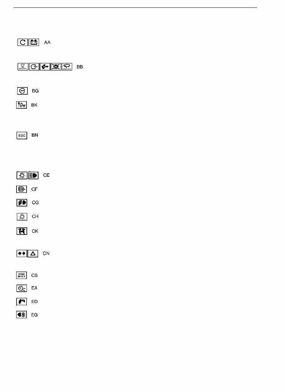
Component wiring diagram index
Starter motor, alternator, 24 V ............................................................ page 6
Coolant level, preheating, exhaust pressure governor,
exhaust brake, range inhibitor, interval wiping .............
page 7
B = Contact extra exhaust brake (RHD)
Engine shut-off .................................................................................... page 7
Speed limiter ....................................................................................... page 8
A = VDO
B = Econocruise
EDC, electronically controlled fuel injection ........................................ page 9
H = MGS
J = AGS
P = Powertronic
Parking lights, side marker lights, roof lights, tail lights
full beams, dipped beams, spotlights ..................................................
page 10
Bulb, position light at mirror ................................................................ page 11
Fog lights ............................................................................................. page 11
Side marker lights ............................................................................... page 11
Brake lights .......................................................................................... page 12
A = AUS
Direction indicator, hazard warning lights ........................................... page 12
A = AUS
Voltage converter ................................................................................ page 12
Reversing lights ................................................................................... page 13
Loading light, fifth wheel light .............................................................. page 13
Rear fog lights ..................................................................................... page 13
2
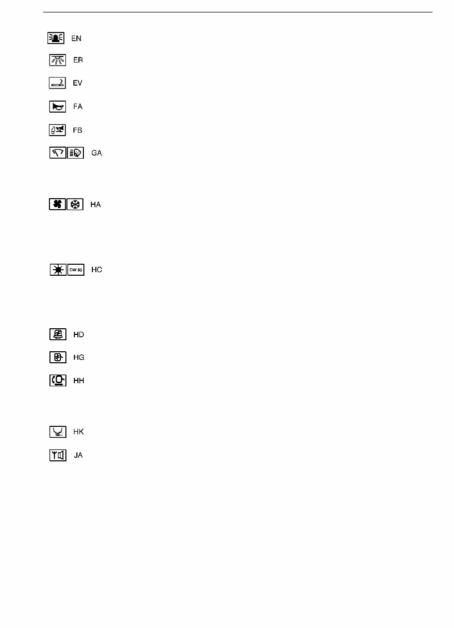
Group 37 Wiring Diagram FL7, FL10 RHD Component wiring diagram index
Rotating warning light .......................................................................... page 13
Interior lights, low cab ......................................................................... page 14
Cigarette lighter, lighting el. distribution center ................................... page 14
Horn ..................................................................................................... page 14
Reverse warner ................................................................................... page 14
Windscreen wipers and washers, headlamp wipers and washers ..... page 15
A = Normal chassis
B = High chassis
Climate unit (air conditioning) ............................................................. page 16
A = CU-ACAUT
B = CU-ACMAN
C = CU-HEAT
Parking heater DW80 .......................................................................... page 18
A = CU-ACAUT
B = CU-ACMAN
C = CU-HEAT
Heated seat ......................................................................................... page 19
Electrically heated rearview mirror ...................................................... page 19
Electrically operated rearview mirror ................................................... page 19
A = VAB2500
B = VAB2600
Air dryer ............................................................................................... page 20
Radio, communication radio and loudspeakers .................................. page 20
A = RHD
3
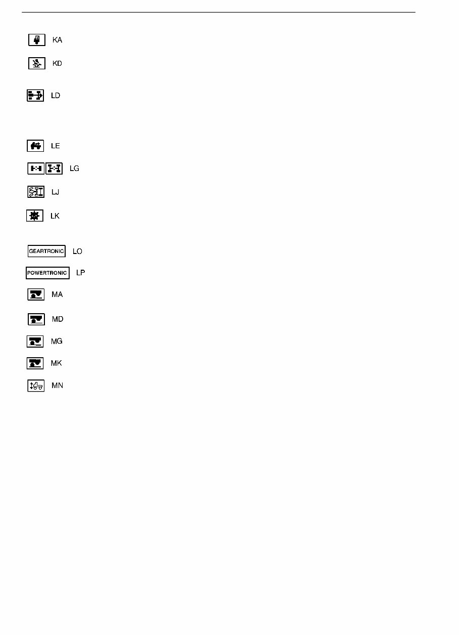
Group 37 Wiring Diagram FL7, FL10 RHD Component wiring diagram index
Electrically operated window winder ................................................... page 21
Seat belt .............................................................................................. page 21
Power take-off ..................................................................................... page 22
A = Power take-off
B = Double power take-off
Power take-off, clutch-independent ..................................................... page 23
Diff. lock ............................................................................................... page 23
Lock, self-steered axle ........................................................................ page 24
Automatic transmission ....................................................................... page 25
J = Powertronic
Geartronic ............................................................................................ page 26
Powertronic .......................................................................................... page 28
Bogie lift (hydraulic) ............................................................................. page 29
Bogie lift (hydraulic), with axle load limiter ......................................... page 30
Bogie lift (air-operated) ........................................................................ page 31
Bogie lift (air-operated), with axle load limiter .................................... page 31
Air suspension ..................................................................................... page 32
A = Tractor
B = Rigid
C = INFOSYST
D = KONVSYST
E = Bogie lift air suspension < 15 tonnes
F = Bogie lift air suspension 15 tonnes
G = Bogie press
4
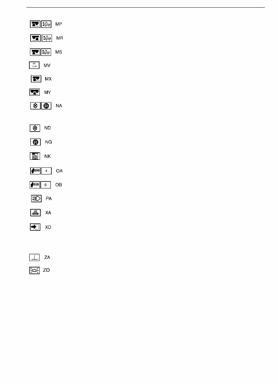
Group 37 Wiring Diagram FL7, FL10 RHD Component wiring diagram index
Bogie lift, air suspension < 15 tonnes ................................................. page 33
Bogie lift, air suspension, pusher ........................................................ page 34
Bogie lift, air suspension 15 tonnes .................................................... page 35
Drive axle load-increase ...................................................................... page 35
Bogie press ......................................................................................... page 36
Bogie lift, tridem .................................................................................. page 36
Combination instrument ...................................................................... page 37
A = Without tachograph
Indicator lamps .................................................................................... page 38
Instruments, buzzer, rheostat .............................................................. page 39
Driver information system (INFOSYST) .............................................. page 40
Anti-lock brakes (ABS), 4–channel ..................................................... page 41
Anti-lock brakes (ABS), 6–channel ..................................................... page 42
Level control, headlights ..................................................................... page 43
6–unit fuse holder ................................................................................ page 43
Connection, extra equipment .............................................................. page 44
A = AVGASB4
B = Powertronic
Earth connections ................................................................................ page 45
Joint sleeve ......................................................................................... page 46
5
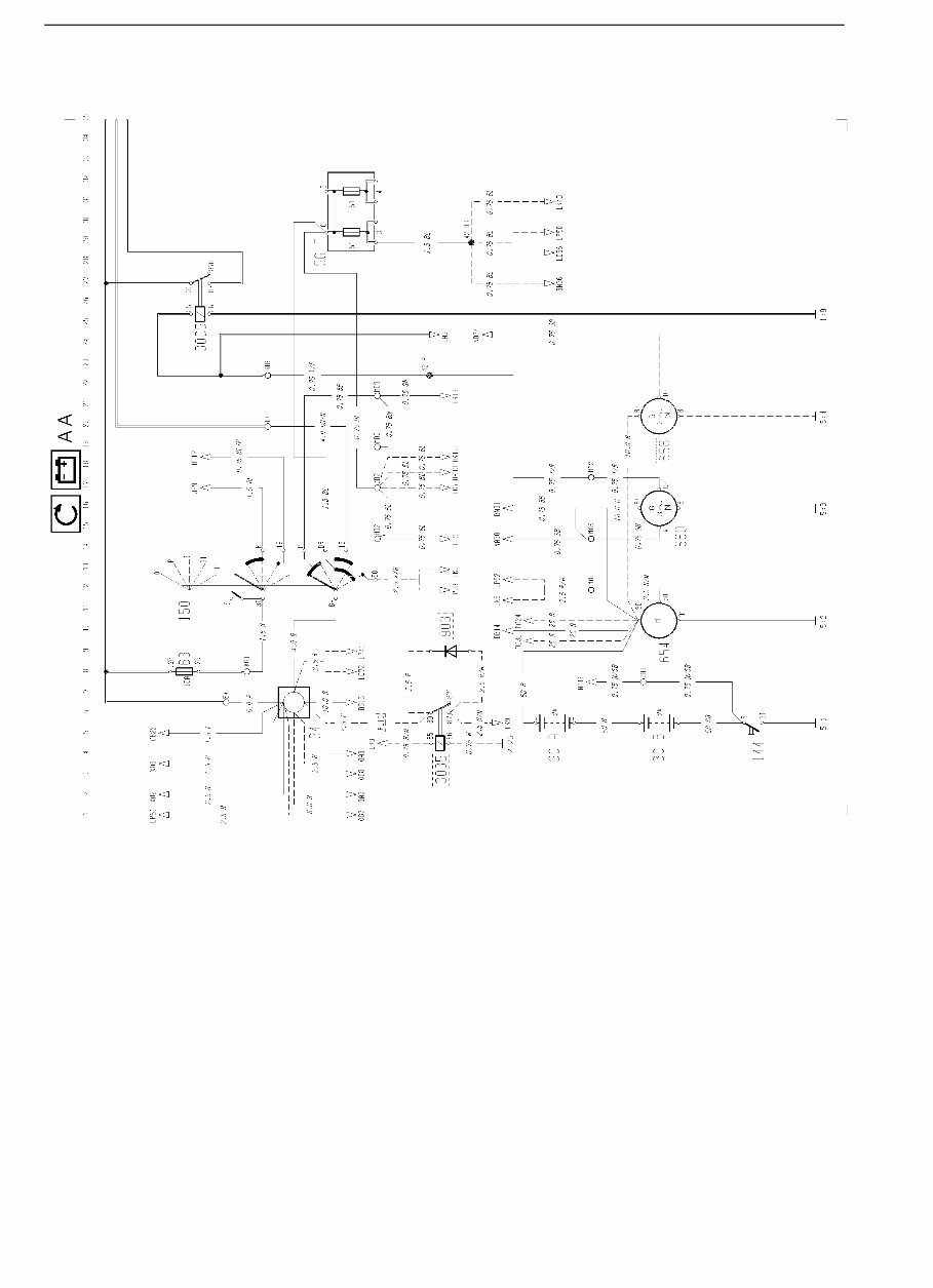
Group 37 Wiring Diagram FL7, FL10 RHD Component wiring diagrams
Component wiring diagrams
T3008262
6
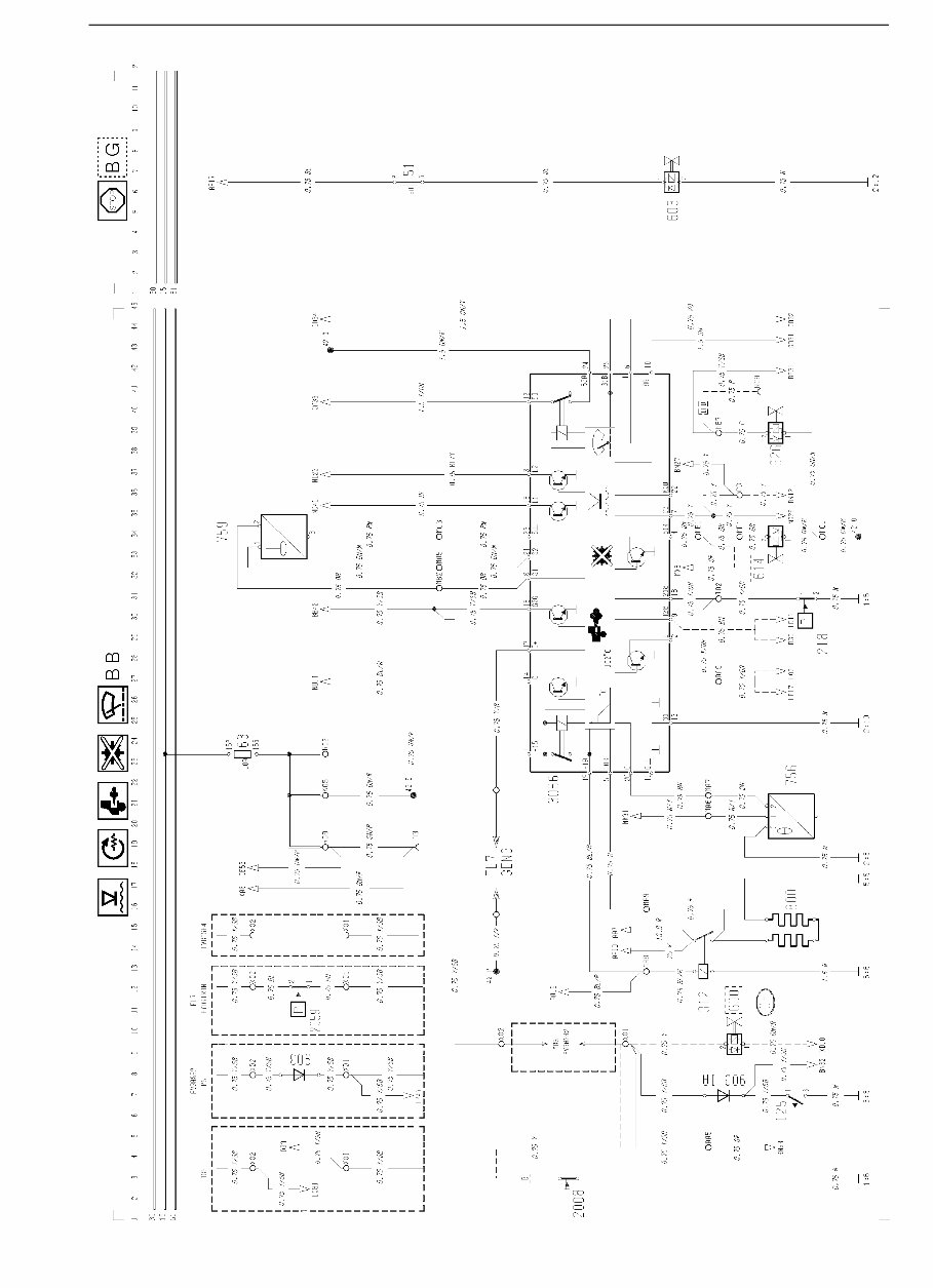
Group 37 Wiring Diagram FL7, FL10 RHD Component wiring diagrams
T3008263
7
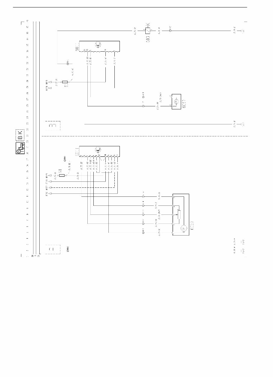
Group 37 Wiring Diagram FL7, FL10 RHD Component wiring diagrams
T3008264
8
You're Reading a Preview
What's Included?
Fast Download Speeds
Online & Offline Access
Access PDF Contents & Bookmarks
Full Search Facility
Print one or all pages of your manual
$35.99
$46.99
Viewed 44 Times Today


Secure transaction
What's Included?
Fast Download Speeds
Online & Offline Access
Access PDF Contents & Bookmarks
Full Search Facility
Print one or all pages of your manual
$35.99
$46.99
Get access to the Volvo FL7 FL10 wiring diagram manual, a comprehensive resource for all your wiring needs. This manual includes:
- Component wiring diagram index
- Component wiring diagrams
- Illustrations
- Fuses on circuit board electrical center
- Relays on circuit board electrical center
- 6-unit fuse holder
- Cable harness illustration index
- List of connectors
- List of components
- Abbreviations
- Cable color code
- And more
This manual is designed for easy access and viewing on your Windows PC, Mac, tablet, smartphone, and more. Print specific sections as needed and discard when the task is done. You also have the option to print the entire manual for a hardcopy reference.


