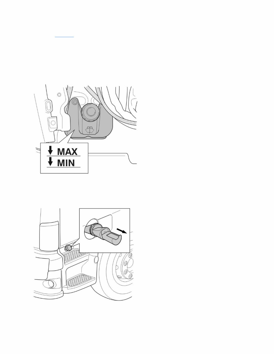
17102-2 Delivery service For the record sheet, see Delivery service Fluid level checks 1 Check fluid levels in windscreen and headlamp washer reservoirs 1 FL 1. Check that the reservoir is filled. 2. Top up with washer fluid as necessary. FL: Windscreen and headlamp washer reservoir FE 1. Check that the reservoir is filled. 2. Top up with washer fluid as necessary. FE: Windscreen washer reservoir Page 1 of 18 sman33311_node72 2/23/2016 http://127.0.0.1:9905/impact3/application/staticdb/lang/enGB/sman33311_node72.xhtm
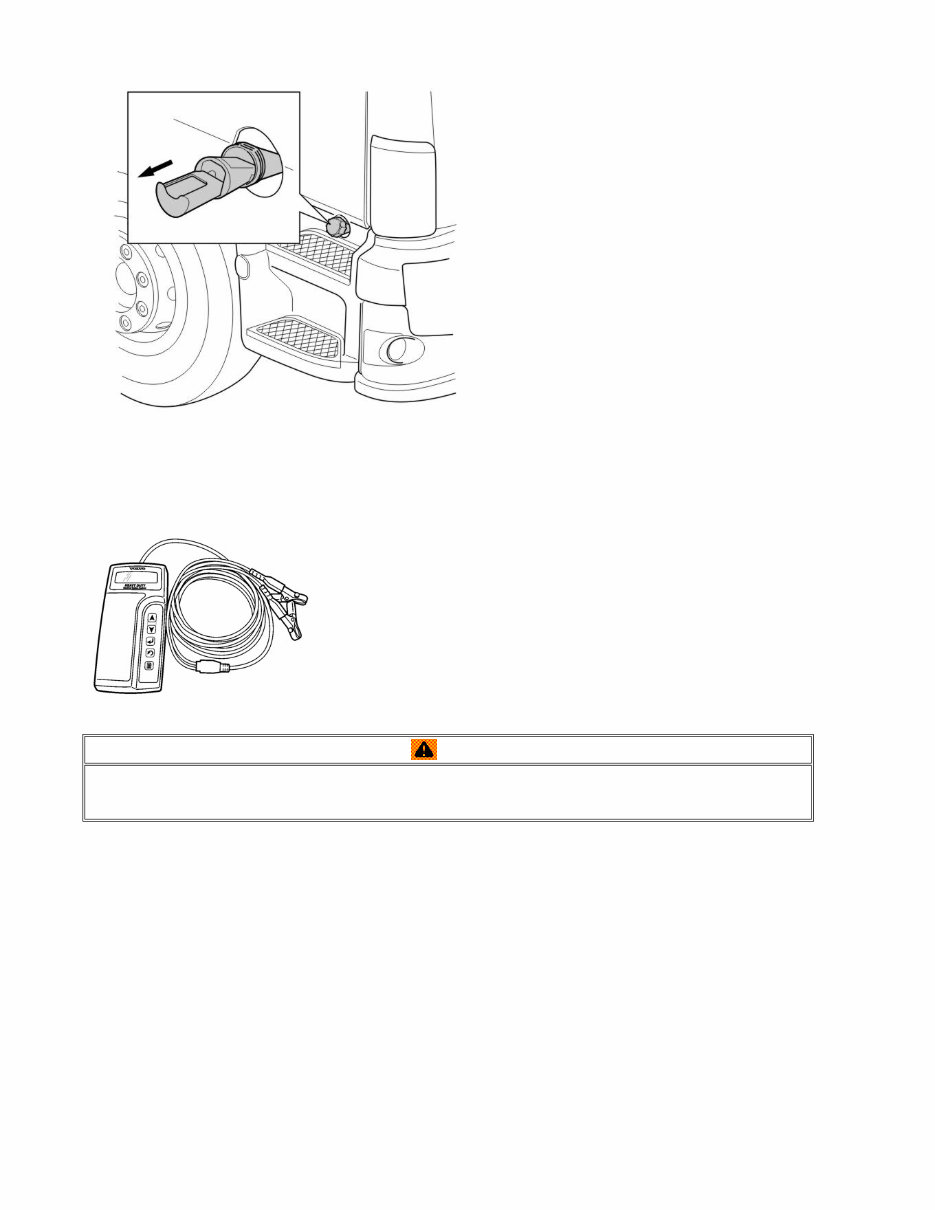
FE: Headlamp washer reservoir 2 Check battery charging and fluid level 1 1. Remove the lid from the battery box. 2. Check the batteries using battery analyser 9812515 or 9812518. Note the battery status in the record sheet. 3. Check the fluid level in the battery cells. Make sure the level in the battery cells is approx. 5 -10 mm above the cell plates, 18–28 mm above the cell plates in countries where temperatures exceed 30°C for more than 3 months per year. Warning When handling batteries: Batteries contain corrosive sulphuric acid. Always wear protective goggles. Do not tilt the battery more than 45°. Page 2 of 18 sman33311_node72 2/23/2016 http://127.0.0.1:9905/impact3/application/staticdb/lang/enGB/sman33311_node72.xhtm
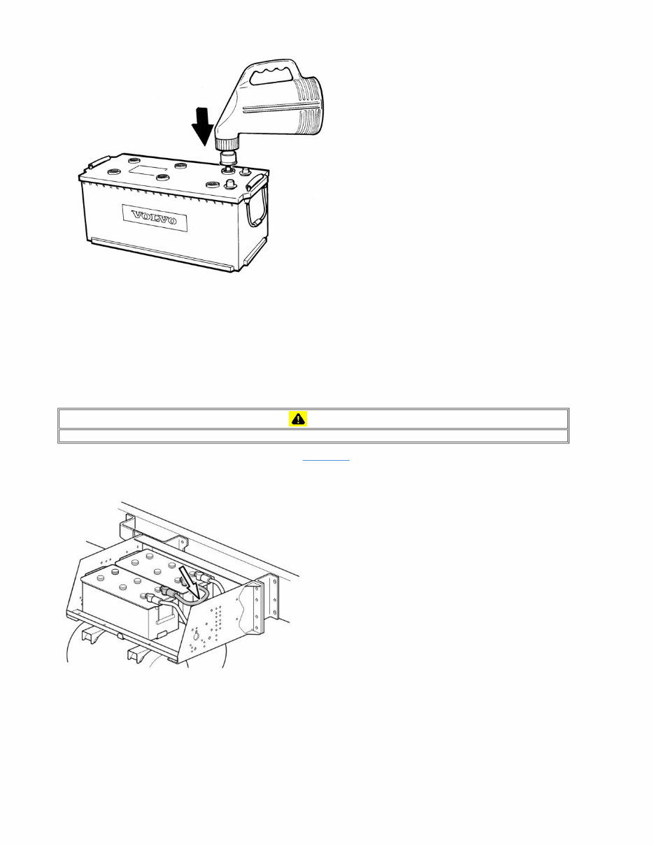
4. Fill with distilled water as necessary to max 10 mm above the plates, max 28 mm above the plates in countries where temperatures exceed 30°C for more than 3 months per year. When charging batteries, please refer to Service Information Group 31. Safety advice for battery charging 1. Always wear protective goggles. 2. Loosen all cell plugs and let them sit loosely in their holes. 3. Switch off the main switch if there is one. 4. Remove at least one terminal from the battery. (Some control units take their current supply directly from the battery.) Rapid chargers must not be used. 5. Charging should be conducted in a well ventilated area. 6. Smoking is not permitted. Avoid open flames and sparks as explosive detonating gas is produced during the charging. 7. Turn the battery charger off before installing/removing the battery charging clamps. For more information about batteries, please refer to the service information group 31, Battery charging . 3 Replace battery cable 1 1. Remove the temporary battery cable, with snap-on couplings, from between the batteries. 2. Put on the correct battery cable which is kept in the vehicle, and pull it tight. 3. Put the lid on the battery box. Checks in cab 4 Activating the radio 1 The radio unit is set to function in only one vehicle. The protection function prevents use of the radio anywhere else. The protection is automatic and no manual handling is usually required. When the power is switched on, the radio is automatically activated. The radio checks that it has the correct code for the truck's instruments. During the check, "ID CHECK" is shown in the Caution Follow the instructions carefully to avoid injury and damage to product or equipment. Page 3 of 18 sman33311_node72 2/23/2016 http://127.0.0.1:9905/impact3/application/staticdb/lang/enGB/sman33311_node72.xhtm
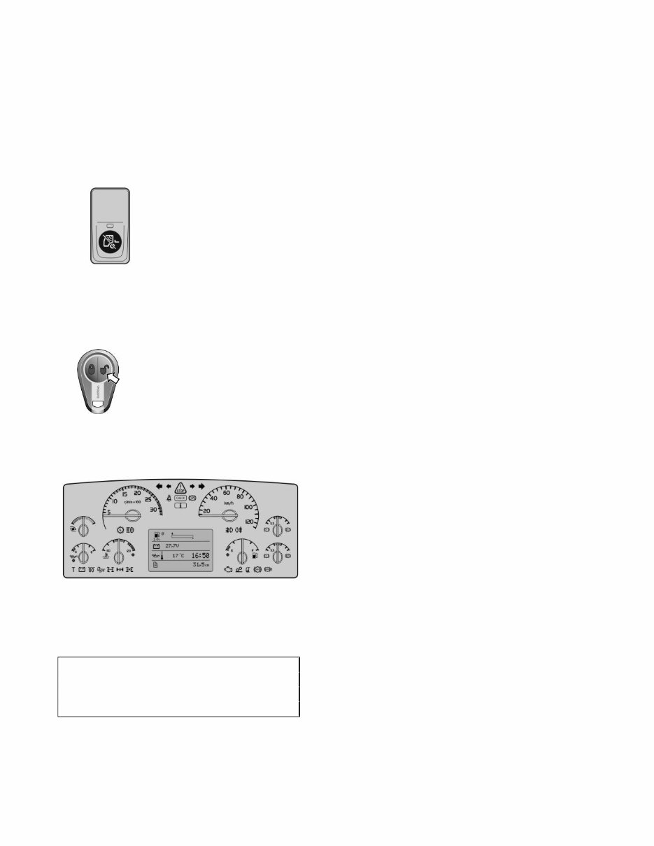
display. The radio is activated if it receives the correct code. If a fault should occur If the radio, for some reason, does not recognise the code, the user will be asked to enter the anti-theft code (the sticker is in the Drivers manual). The display then shows "CODE 0000". Do the following to enter the code: 1 Turn the volume knob until the flashing digit shows the correct digit. 2 Press the On/Off button to save the digit. The next digit will start to flash. 3 Repeat steps 1 and 2 until all four digits are entered. The user has three attempts to enter the code. If unsuccessful, the radio will be locked for 60 minutes before three new attempts are allowed. For more information see Drivers manual. 5 Activating the theft alarm 1 The alarm can be in the service mode at delivery and then needs to be activated. The symbol for service mode is shown in the display as long as the starter key is in the drive position. To leave the service mode and activate the alarm, do as follows: 1. Turn the starter key to drive position 2. Hold the switch down to switch off the motion detectors 3. Press the UNLOCK symbol on the remote control 4. Check that the LED on the instrument panel goes out The symbol for service mode goes out in the display and the alarm is activated. 6 Checking warning and indication lamps 1 The instrument clusters can be separated into two groups, one group with a large display and one group with a small display. Use the vehicle manual as a guide when carrying out this check. Instrument cluster with large display In order to test warning and control lamps on this type of instrument, the engine must be switched off with the starter key in drive position. Test warning and control lamps with the aid of the control lever on the right hand side of the steering wheel and instrument display. 1. Scroll to MENU: FAULT DIAGNOSIS/INSTRUMENT TEST/CONTROL LAMP TEST on the display. CONTROL LAMP TEST GAUGE TEST DISPLAY TEST BUZZER TEST Page 4 of 18 sman33311_node72 2/23/2016 http://127.0.0.1:9905/impact3/application/staticdb/lang/enGB/sman33311_node72.xhtm
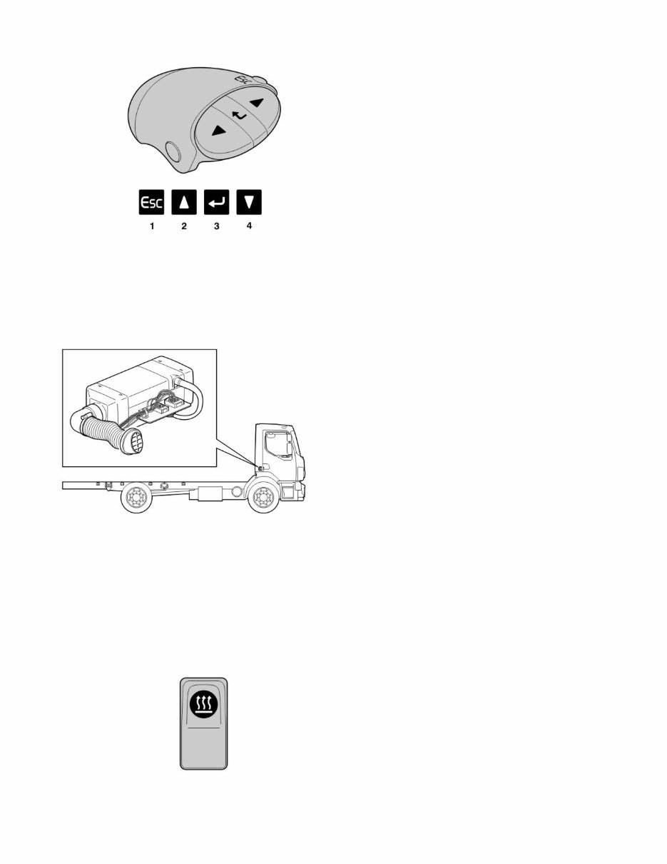
2. Depress SELECT (3) whenCONTROL LAMP TEST is indicated on the display. The warning lamps and check lamps on the instrument light up and extinguish in intervals. 3. To stop the tests, press Esc (1). Instrument cluster with small display To test warning and control lamps on this type of instrument, the ignition key must be turned from 0 to drive position. In this position, all warning and control lamps in the instrument cluster will light up for a few seconds. 7 Function check of the parking heater 1 Use the Parking Heater User Manual as a guide. 1. If the vehicle is equipped with a parking heater, start and run the parking heater for 15 minutes to check its function. Note: Do not stop the parking heater until it has been running for at least 15 minutes. 2. If the heater malfunctions, check the heater and remedy any faults. Use Service Literature, Group 87, as guidance. Quick start/manual stopping of parking heater 8 Checking the fault codes in the vehicle’s control units Quick start Press once on the switch to start the parking heater. Manual stopping Press once on the switch to switch off the parking heater. Page 5 of 18 sman33311_node72 2/23/2016 http://127.0.0.1:9905/impact3/application/staticdb/lang/enGB/sman33311_node72.xhtm
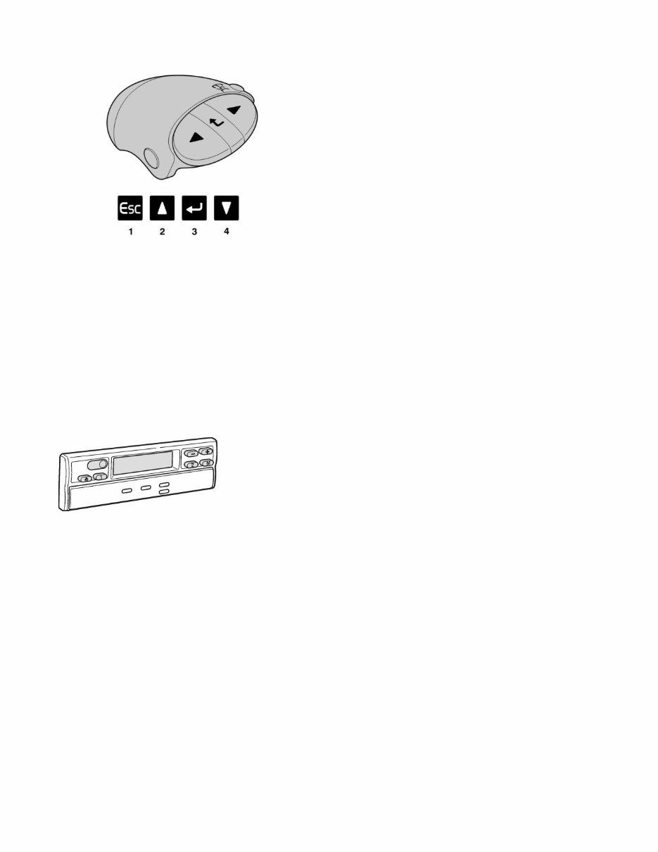
1 Use Service Information Group 03 as an aid and also fault code information for each respective system. The instruments, vehicle control units and engine control units are always included in the system. Other control units included depend on the type of vehicle, legal requirements and vehicle specifications. The engine must be switched off during a check and the ignition key in drive position. Use the control lever on the right side of the steering wheel to read any error codes on the instrument display. 1. Use the control lever and display to see whether fault codes are stored in any of the control units in the vehicle. 2. Make a note of the error codes, if any. 3. Deal with the error codes. 4. Zero the fault codes after action. Error codes can also be read by means of a PC, via the data link connector. 9 Checking the tachograph Use the Tachograph User Manual as a guide. 1 Check that the tachograph is connected to the vehicle's batteries. Carry out the points below if the vehicle's battery has been disconnected or if the power to the tachograph has been disconnected in any other way. The diagram sheet case and clock must be synchronised or the clock display will flash. 1. Put the starter key in drive position. 2. Remove the diagram sheets from the diagram sheet case. 3. Close the diagram sheet case, the clock will stop flashing. 4. Insert new diagram sheets when the vehicle is to be used. When the power supply to the tachograph has been broken a fault code will be set (which will not be shown in the tachograph display). Such an error code can be removed at the next calibration occasion. Note: Before a test drive is carried out, a diagram sheet must be inserted into the tachograph (since a power is registered during the initial drive). Use Service Information, Group 38, as a guide. Digital tachograph 2 Page 6 of 18 sman33311_node72 2/23/2016 http://127.0.0.1:9905/impact3/application/staticdb/lang/enGB/sman33311_node72.xhtm
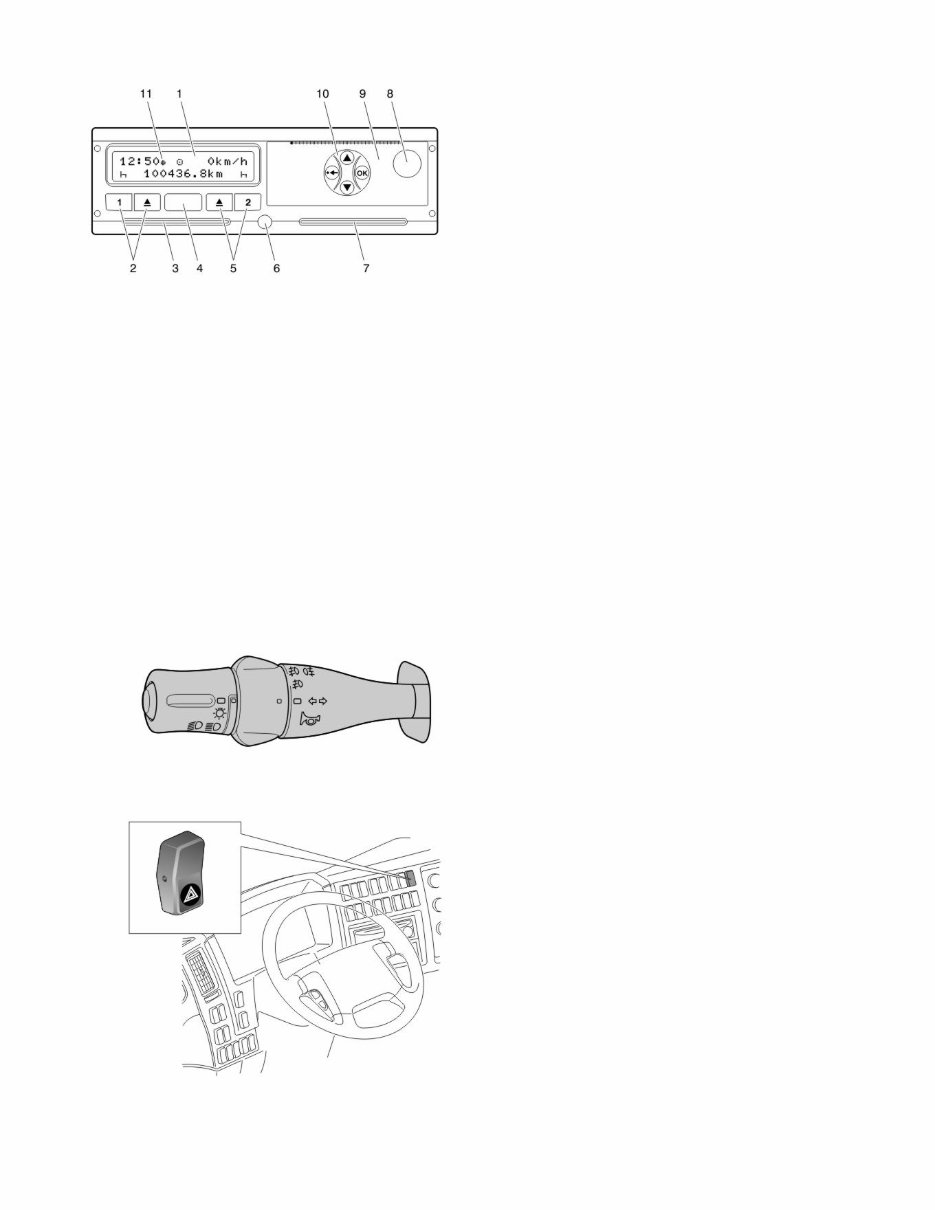
1. Display 2. Button panel driver 1 (driver activity driver 1/ejection of card, card reader 1) 3. Card slot 1 4. Communication interface 5. Button panel driver 2 (driver activity driver 2/ejection of card, card reader 2) 6. Sealing the unit 7. Card slot 2 8. Printer opening button 9. Printer cover 10. Menu button 11. Symbol showing that local time is set 1. Check that the tachograph is connected to the vehicle's batteries. 2. If the vehicle battery has been disconnected or if power has been removed from the tachograph in any other way, the display should be checked for fault messages when the ignition key is turned to the driving position. When the power to the tachograph has been disconnected, a fault code will be set and a fault message will be shown on the display. The fault message is deleted with the OK-button, while the fault code must be deleted at the next calibration. Note that the tachograph must be activated with a workshop card and PIN-code in order to be fully functional. Final calibration of the tachograph and registration of the vehicle registration number shall be performed before delivery to the customer. Use service information, group 38, and the tachograph instruction book as a guide. 10 Function check of direction indicators and warning flashers 1 1. Move the indicator lever. 2. Check that the direction indicator lamps on the trailer and the control lamps on the instrument display light up. 3. Switch on the warning flasher and check that all the indicator lamps on the trailer illuminate. The switch should flash in unison with these. 11 Function check of lighting, horn and cigarette lighter Page 7 of 18 sman33311_node72 2/23/2016 http://127.0.0.1:9905/impact3/application/staticdb/lang/enGB/sman33311_node72.xhtm
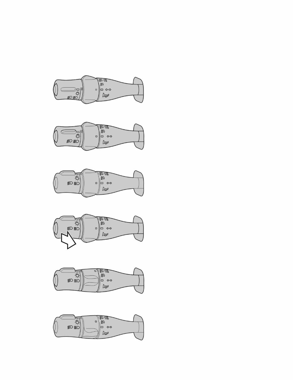
1 Use the User Manual for each vehicle as a guide. Check: 1. The instrument lighting. 2. The lighting in the switches. 3. The interior lighting. 4. The horn. 5. The cigarette lighter 6. All external lamps. Light stalk, neutral Parking lights Dipped beam Full beam Front and rear fog Front fog lights Page 8 of 18 sman33311_node72 2/23/2016 http://127.0.0.1:9905/impact3/application/staticdb/lang/enGB/sman33311_node72.xhtm
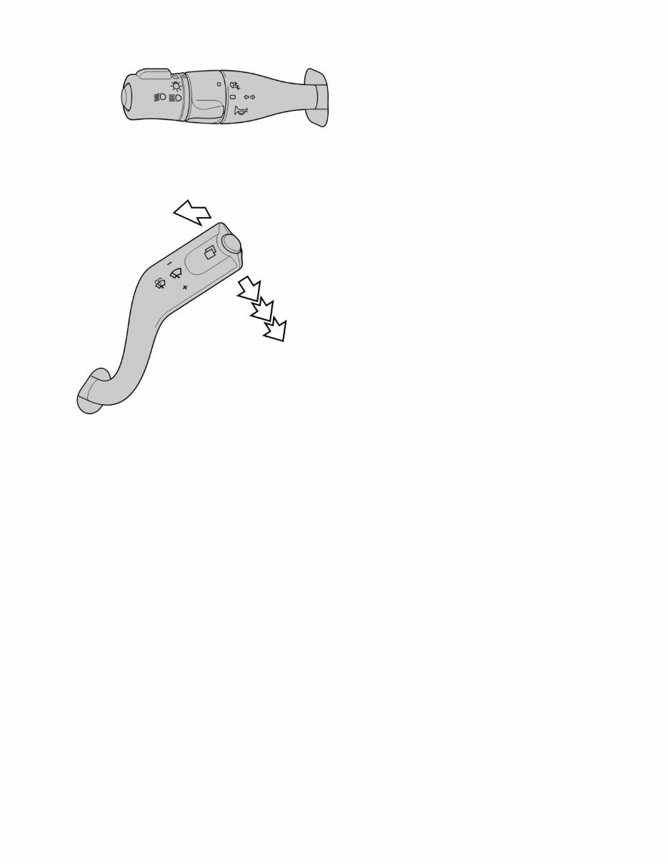
Rear fog light 12 Function check of washers – windscreen and headlamp washers 1 See the User Manual for each vehicle. Windscreen wipers, check that: 1. the windscreen washer jets hit the windscreen satisfactorily 2. the windscreen wipers wipe the window clean 3. the windscreen wipers have two wiping speeds 4. the wiping intervals are functioning 5. the windscreen wipers stops in parking position 6. the windscreen wipers operate 2-3 extra times after washing. Headlamp washers, check that: 1. the telescopic function of the washer nozzle is effective and that the headlamp washer jets hits the headlamps. 13 Check of windows 1 Page 9 of 18 sman33311_node72 2/23/2016 http://127.0.0.1:9905/impact3/application/staticdb/lang/enGB/sman33311_node72.xhtm
Get your hands on the VOLVO FE, LORRY AND BUS SERVICE AND REPAIR MANUAL, a comprehensive guide for fixing problems in your vehicle. Whether you're a professional mechanic or a DIY enthusiast, these Auto Repair Manuals provide detailed instructions and procedures to help you tackle any issue with your ride. With over 20 years of experience in auto repair and body work, the manuals offer invaluable customer support via email, ensuring you get your car fixed right the first time.
Constant use can cause even the most durable vehicles to deteriorate, and when that happens, you'll need to replace parts. With a trusty repair manual, you can save money and enjoy the satisfaction of do-it-yourself projects. The manual includes technical data, diagrams, a complete list of car parts, and illustrations, making it easy for even novice mechanics to follow the step-by-step guides. Additionally, you'll find a comprehensive list of accessories to enhance your engine's performance.
The repair manuals contain the same information used by the company's engineers and cover a wide range of sections, including maintenance, engine, control system, mechanical, fuel service specifications, and much more. These manuals are available in both .PDF and .OVA file formats, compatible with Windows Vista32 and 64, XP, ME, 98, NT, 2000, and Mac.
By having these manuals, you can save time and become more knowledgeable about your car, eliminating the need to rely solely on your mechanic for even the simplest repairs. The convenience of printable pages allows you to take the manual with you into the garage or workshop without worrying about it getting dirty or torn. It's a valuable resource that keeps your car knowledge up-to-date and empowers you to take control of your vehicle's maintenance and repairs.
Compatible with all versions of Windows and Mac, these Auto Repair Manuals are a must-have for anyone looking to maintain, service, diagnose, and repair their vehicle with ease. They are also printable, making it convenient to have the necessary information at your fingertips whenever you need it.
Maintenance
Engine
Control System
Mechanical
Fuel Service Specifications
Emission Control
Intake Exhaust Cooling
Lube
Ignition Starting Charging
Auto Transmission Clutch
Manual Transmission
Transfer Propeller Shaft
Drive Shaft
Differential
Axle Suspension
Tire & Wheel
Brake Control
Brake
Parking Brake
Steering Column
Power Steering
Air Condition
Suppl Restraint System
Seat Belt
Engine Immobilizer
Cruise Control
Wiper & Washer
Door Lock
Meter Audio/Visual
Horn
Windshield/Glass Mirror
Instrument Panel
Seat
Engine Hood/ Door
Exterior & Interior
Electrical
Multiplex/ Can Communication
And much more...
These Auto Repair Manuals provide a wealth of information, including wiring schematics, diagrams, and illustrations, to help you service and repair your vehicle comprehensively. They are a valuable resource for anyone looking to take charge of their car's maintenance and repairs.