

1998-2009 Sterling Acterra MX Trucks OEM Service & Repair Manual
What's Included?
Fast Download Speeds
Online & Offline Access
Access PDF Contents & Bookmarks
Full Search Facility
Print one or all pages of your manual

ACTERRA WORKSHOP MANUAL
Models: MX
STI-414, S19 (7/10P)
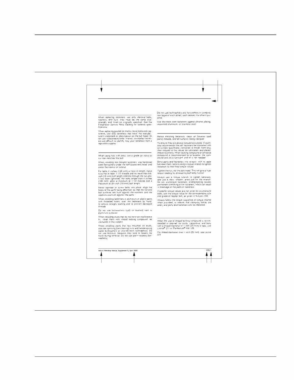
For an example of an Acterra Workshop Manual page, see Fig. 1.
B C A
F G D E
Threaded Fasteners
Fastener Replacement
Fastener Selection and Installation
Fastener Tightening
Thread Locking Compound
Application
General Instructions
00.04
01/20/2000
f020104
A. Section Title
B. Section Number (made up of the Group Number—first two digits, followed by a sequence number—last two digits)
C. Subject Title
D. Manual Title
E. Release (Supplement) Date
F. Subject Number
G. Subject Page Number
Fig. 1, Example of an Acterra Workshop Manual Page
Introduction
Page Description
Acterra Workshop Manual, Supplement 19, July 2010 I–3

Group No. Group Title
00 ...................... General Information
01 ................................ Engine
09 .............................. Air Intake
13 ......................... Air Compressor
15 ................... Alternators and Starters
20 ................... Engine Cooling/Radiator
25 ................................ Clutch
26 ........................... Transmission
30 ......................... Throttle Control
31 ............. Frame and Frame Components
32 ............................ Suspension
33 ............................. Front Axle
35 ............................. Rear Axle
40 ........................ Wheels and Tires
41 .............................. Driveline
42 ................................ Brakes
46 ............................... Steering
47 ................................. Fuel
49 ............................... Exhaust
54 .......... Electrical, Instruments, and Controls
60 .................................. Cab
72 ................................ Doors
82 ............. Windshield Wipers and Washer
83 ................. Heater and Air Conditioner
88 .............. Hood, Grille, and Cab Fenders
90 ................. Fire Suppression Systems
91 ............... Seats and Restraint Systems
98 ................................. Paint
Introduction
Workshop Manual Contents
I–4 Acterra Workshop Manual, Supplement 19, July 2010

Vehicle Receipt
Prior to signing for vehicle delivery from a transporter
company, the dealer is responsible for checking for
transporter-related shortages or damages, and noting
these discrepancies on the transporter’s delivery re-
ceipt.
The dealer is also responsible for ensuring that the
vehicle was built according to the Truck Sales Order/
Invoice.
Refer to Section 3 of the Daimler Trucks North
America LLC Warranty Manual for details.
Vehicle Storage
There may be times when a vehicle is stored for long
periods before customer delivery. To protect all ve-
hicles from deterioration and weather, they must be
properly maintained. Adequate protection and stor-
age of new vehicles is the responsibility of the
dealer.
Claims arising from loss and damage to improp-
erly stored vehicles will not be reimbursed.
See Section 3 of the Daimler Trucks North America
LLC Warranty Manual for instructions on storage of
new vehicles.
Pre-Delivery Information
All pre-delivery inspections and services must be
performed at an authorized Daimler Trucks North
America LLC facility, assigned to fully qualified ser-
vice personnel and recorded on the "New Vehicle
Pre-Delivery Inspection" form.
Refer to Section 3 of the Daimler Trucks North
America LLC Warranty Manual for details.
It is recommended the pre-delivery inspection be per-
formed within 30 days of vehicle receipt.
Vehicle Receipt, Storage, and Pre-Delivery Information 00.01
General Information
Acterra Workshop Manual, Supplement 15, January 2008 050/1

Cooling System
1. Cooling system hoses must clear all moving
parts by a minimum of 1/4 inch (6 mm).
2. The 1-inch (25-mm) hose from the surge tank to
the engine must be free of sumps and have al-
lowance for engine torque.
3. All hoses from the engine hard pipes must be
wrapped in convoluted tubing.
4. Hoses that are protected with convoluted tubing
may be secured with tie straps to clear the inner
fenders.
5. Cooling system hoses should not be twisted or
kinked.
6. Cooling system hoses must be routed at least 6
inches (152 mm) from a heat source if the heat
source does not have a heat shield. If a heat
shield is provided, the hose must be routed at
least 3 inches (76 mm) from the heat source.
HVAC System
1. Cushion clamps are required to support all A/C
lines. Butterfly or figure-8 clamps (two cushion
clamps) may be used to prevent rubbing or chaf-
ing.
2. Heater hoses that are protected with convoluted
tubing may be fastened with tie straps. If not pro-
tected with convoluted tubing, only cushion
clamps or butterfly clamps may be used for
heater hoses.
3. A/C lines cannot be secured to air lines, fuel
lines, or electrical wires.
4. HVAC hoses should be protected from damage
by routing them away from hazards of heat,
wheel splash (water, gravel, ice), human traffic,
and moving parts of the vehicle.
5. HVAC hoses should be routed away from sharp
points and edges (such as nuts, bolts, brackets,
and frame rail edges), moveable parts, and
sources of abrasion, cutting, pinching, or crush-
ing.
NOTE: If hoses are covered with convoluted
tubing, they may touch any of the above.
6. Hoses that are protected with convoluted tubing
may come in contact with the bends on frame
rails and filters.
7. HVAC hoses must be routed at least 6 inches
(152 mm) from a heat source if the heat source
does not have a heat shield. If a heat shield is
provided, the hose must be routed at least 3
inches (76 mm) from the heat source.
8. All HVAC hoses must be routed so that regularly
serviced components, such as fuel filters, fuel/
water separators, oil filters, air filters, belts, and
fill and drain plugs, are readily accessible for ad-
justment or replacement without the need to relo-
cate or remove the hoses.
9. All A/C hoses in the engine compartment must
have convoluted tubing.
10. If cushion clamps are used over convoluted tub-
ing at existing clamp points, no additional tie
straps or tape is needed.
11. When convoluted tubing is installed on the
heater hose where it routes past the splash
shield on the front right-hand side of the firewall,
and if it uses existing clamps, no additional tie
straps or tape is needed.
Auxiliary Heater
All auxiliary heater lines are deck-mounted hard pip-
ing with rubber hose at both ends. No additional tie
straps are required.
Engine Plumbing
1. On vehicles equipped with the Cummins ISM
engine and power steering, no additional tie
straps or tape are needed if convoluted tubing is
installed on the power steering hose where it
routes under the frame rail.
2. The engine oil pressure line should not rub or
chafe against the Teflon
®
discharge line.
Electrical Wiring
1. Wires that are bundled together should be fas-
tened at 8- to 12-inch (203- to 305-mm) intervals.
If anchor clamps are more than 12 inches (305
Vehicle Receipt, Storage, and Pre-Delivery Information 00.01
Hoses and Electrical Wiring Routing Standards
Acterra Workshop Manual, Supplement 5, September 2002 100/1

mm) apart, a tie strap must be used between the
anchor clamps.
2. Bundles of wires that are located in an exposed
area, such as under the cab or outside the frame
rail, need to be fastened with heavy-duty cable
ties
3. Any wiring that will be exposed to water or heat
must be covered with either loom or convoluted
tubing. Loom or convoluted tubing need not butt
up against Weather Pack
®
connectors.
4. Any wiring routed across the vehicle, on the en-
gine crossmember, or across the rear of the en-
gine, must be secured with a clamp or tie strap,
and covered with either convoluted tubing or a
loom.
5. Any wiring that may come into contact with sharp
points and edges (such as nuts, bolts, brackets,
and frame rail edges), moveable parts, and
sources of abrasion, cutting, pinching, or crush-
ing, must be protected by either a loom or con-
voluted tubing.
6. Unprotected breakouts (individual wires) of up to
8 inches (203 mm) are acceptable as long as
these wires are routed safely away from sharp
points and edges, moveable parts, and sources
of abrasion, cutting, pinching, or crushing.
7. Gray, flame-retardant convoluted tubing may be
used to protect wiring in the cab or the chassis.
Black nylon convoluted tubing may only be used
in the chassis.
8. All wiring must be routed so that regularly ser-
viced components, such as fuel filters, fuel/water
separators, oil filters, air filters, belts, and fill and
drain plugs, are readily accessible for adjustment
or replacement without the need to relocate or
remove any wiring.
9. In exposed locations, such as the road light har-
ness near the headlights, loose loops of wire
must be secured with tie straps.
10. All wiring should be routed a minimum of 4
inches (102 mm) from the exhaust. In situations
where the wiring is less than 4 inches (102 mm)
from the exhaust, a heat shield must be placed
between the wiring and the exhaust.
Battery Cables
1. Battery cables must be routed along an unob-
structed path from the starter to the battery box.
The cables must not rub or chafe on brackets,
tanks, air lines, or fuel lines.
2. Battery cables and electrical wiring cannot be
tied or secured to fuel lines, discharge lines, or
air lines.
3. Battery cables must have support brackets no
more than 30 inches (762 mm) apart. Tie straps
must be within 6 inches (152 mm) of both sides
of the support brackets, and every 12 inches
(305 mm) between the brackets.
4. Battery cables must have convoluted tubing from
the frame bracket to the batteries, and from the
frame bracket to the starter.
Fuel Lines
1. Fuel lines must not be clamped to A/C lines, bat-
tery cables, jumper cables, or any other electrical
wiring.
2. Stand-off brackets or clamps may be used to
prevent fuel lines from rubbing against the frame.
3. Fuel lines must be routed at least 6 inches (152
mm) from a heat source. If a heat shield is pro-
vided, the fuel line must be at least 3 inches (76
mm) from the heat source.
4. Fuel lines that are parallel may be fastened to-
gether. Fuel lines that cross or that rub on metal,
plastic, or electrical parts, need to be separated
with butterfly clamps.
Chassis Air Lines and Brake
Hoses
1. Hoses may come in contact with each other if
they are parallel, or if they are bundled together.
2. If the hoses lie on the curve or flat surface of a
bracket or crossmember, they do not need con-
voluted tubing.
3. Brake hoses may be clamped at the top of the
axle housing, and touch or lie against the axle
housing in its path to the brake chamber as this
assembly moves together.
Vehicle Receipt, Storage, and Pre-Delivery Information 00.01
Hoses and Electrical Wiring Routing Standards
Acterra Workshop Manual, Supplement 5, September 2002 100/2

4. Brake hoses must have slack between the last
clamping point on the frame rail and the brake
chamber to allow for full range of suspension
travel.
5. Brake hoses should have butterfly clamps at
breakout points.
6. Air lines and brake hoses that are bundled to-
gether should be fastened at 8- to 12-inch (203-
to 305-mm) intervals. If anchor clamps are more
than 12 inches (305 mm) apart, a tie strap must
be used between the anchor clamps. Tie straps
may be closer than 12 inches (305 mm) apart.
7. Hoses or lines that may come into contact with
the sharp edge of a bracket or frame rail are to
be protected by convoluted tubing.
8. Air lines and brake hoses that are parallel may
be fastened together. Air lines and brake hoses
that cross or that rub on metal, plastic, or electri-
cal parts need to be separated with butterfly
clamps.
9. Nylon or STX (wire braid) chassis air lines may
be fastened together to prevent rubbing, as long
as the lines are stationary.
Vehicle Receipt, Storage, and Pre-Delivery Information 00.01
Hoses and Electrical Wiring Routing Standards
Acterra Workshop Manual, Supplement 5, September 2002 100/3

U.S. Customary to Metric Metric to U.S. Customary
When You Know
Multiply
By
To Get When You Know
Multiply
By
To Get
Length
inches (in) 25.4 millimeters (mm) 0.03937 inches (in)
inches (in) 2.54 centimeters (cm) 0.3937 inches (in)
feet (ft) 0.3048 meters (m) 3.281 feet (ft)
yards (yd) 0.9144 meters (m) 1.094 yards (yd)
miles (mi) 1.609 kilometers (km) 0.6215 miles (mi)
Area
square inches (in
2
) 645.16 square millimeters (mm
2
) 0.00155 square inches (in
2
)
square inches (in
2
) 6.452 square centimeters (cm
2
) 0.15 square inches (in
2
)
square feet (ft
2
) 0.0929 square meters (m
2
) 10.764 square feet (ft
2
)
Volume
cubic inches (in
3
) 16387.0 cubic millimeters (mm
3
) 0.000061 cubic inches (in
3
)
cubic inches (in
3
) 16.387 cubic centimeters (cm
3
) 0.06102 cubic inches (in
3
)
cubic inches (in
3
) 0.01639 liters (L) 61.024 cubic inches (in
3
)
fluid ounces (fl oz) 29.54 milliliters (mL) 0.03381 fluid ounces (fl oz)
pints (pt) 0.47318 liters (L) 2.1134 pints (pt)
quarts (qt) 0.94635 liters (L) 1.0567 quarts (qt)
gallons (gal) 3.7854 liters (L) 0.2642 gallons (gal)
cubic feet (ft
3
) 28.317 liters (L) 0.03531 cubic feet (ft
3
)
cubic feet (ft
3
) 0.02832 cubic meters (m
3
) 35.315 cubic feet (ft
3
)
Weight/Force
ounces (av) (oz) 28.35 grams (g) 0.03527 ounces (av) (oz)
pounds (av) (lb) 0.454 kilograms (kg) 2.205 pounds (av) (lb)
U.S. tons (t) 907.18 kilograms (kg) 0.001102 U.S. tons (t)
U.S. tons (t) 0.90718 metric tons (t) 1.1023 U.S. tons (t)
Torque/Work Force
inch-pounds (lbf·in) 11.298 Newton-centimeters (N·cm) 0.08851 inch-pounds (lbf·in)
foot-pounds (lbf·ft) 1.3558 Newton-meters (N·m) 0.7376 foot-pounds (lbf·ft)
Pressure/Vacuum
inches of mercury (inHg) 3.37685 kilo Pascals (kPa) 0.29613 inches of mercury (inHg)
pounds per square inch (psi) 6.895 kilo Pascals (kPa) 0.14503 pounds per square inch (psi)
When You Know Subtract
Then
Divide By
To Get When You Know
Multiply
By
Then
Add
To Get
degrees Fahrenheit (°F) 32 1.8 degrees Celsius (°C) 1.8 32 degrees Fahrenheit (°F)
Metric/U.S. Customary Conversion Charts 00.02
General Information
Acterra Workshop Manual, Supplement 6, September 2004 050/1

IMPORTANT: See Subject 060 for the vehicle
identification numbering system for vehicles built
May 1, 2000, or later.
Federal Motor Vehicle Safety Standard 115 specifies
that all vehicles sold in the U.S. be assigned a 17-
character Vehicle Identification Number (VIN). Using
a combination of letters and numerals, the VIN de-
fines the manufacturer, model, and major characteris-
tics of the vehicle. See Table 1 for the character po-
sitions of a typical Sterling VIN,
480ALEBDXWA345678.
The VIN can be found on the Vehicle Specification
Decal (see the driver’s manual for decal location)
and stamped on the outside of the left-hand frame
rail about 24 to 40 inches (60 to 100 cm) aft of the
front axle centerline. On Sterling vehicles built before
July 1998, the VIN is stamped on the frame rail near
the front axle position.
IMPORTANT: A new VIN-code structure will be
used for all vehicles built after April 30, 2000.
Character positions 1 through 4 and 9 through
17 are nearly the same in both versions, but
positions 5 through 8 have been assigned
slightly different parameters. As a result, the
build date of a vehicle must be determined be-
fore the VIN can be decoded.
For all vehicles, a check digit (9th character) is deter-
mined by assignment of weighted values to the other
16 characters. These weighted values are processed
through a series of equations designed to check va-
lidity of the VIN and to detect VIN alteration.
NOTE: Always specify the VIN when ordering
parts.
Seventeen-Character Vehicle Identification Number (VIN)
Typical VIN 480 A L EB D X W A 345678
Character Position 1, 2, 3 4 5 6, 7 8 9 10 11 12 thru 17
Decoding Table
*
Table 2 Table 3 Table 4 Table 5 Table 6 — Table 7 Table 8 —
Code Description
Manufacturer, Make, Vehicle Type
Chassis, Front Axle Position, Brakes
Vehicle Model Series, Cab
Engine Model, Horsepower Range
Gross Vehicle Weight Rating (GVWR)
Check Digit
Vehicle Model Year
Plant of Manufacture
Production Number
* For corresponding decoding information, see the applicable tables in this subject.
Table 1, Seventeen-Character Vehicle Identification Number (VIN)
VIN Positions 1, 2, and 3 (Manufacturer, Make, Vehicle Type)
Code Vehicle Manufacturer Vehicle Make Vehicle Type
2FW Sterling, Canada-built Sterling Truck-Tractor
2FZ Sterling, Canada-built Sterling Incomplete Vehicle
480 Sterling, U.S.-built Sterling Truck-Tractor
Vehicle Identification Numbering System 00.03
VIN for Vehicles Built through April 30, 2000
Acterra Workshop Manual, Supplement 1, June 2000 050/1

VIN Positions 1, 2, and 3 (Manufacturer, Make, Vehicle Type)
Code Vehicle Manufacturer Vehicle Make Vehicle Type
49H Sterling, U.S.-built Sterling Incomplete Vehicle
Table 2, VIN Positions 1, 2, and 3 (Manufacturer, Make, Vehicle Type)
VIN Position 4 (Chassis, Front Axle Position, Brakes)
Code Chassis
Front Axle
Position
Brakes
A 4 x 2 Truck Forward Hydraulic
B 8 x 4 Truck-Tractor Setback Air
C 6 x 6 Truck-Tractor Setback Air
D 4 x 4 Truck Setback Hydraulic
E 4 x 4 Truck Setback Air
F 8 x 4 Truck Forward Air
G 8 x 4 Truck-Tractor Forward Air
H 4 x 2 Truck Forward Air
J 10 x 4 Truck All Air
K 4 x 2 Truck-Tractor Forward Air
L 6 x 2 Truck Forward Air
M 6 x 2 Truck-Tractor Forward Air
N 6 x 4 Truck Forward Air
P 6 x 4 Truck-Tractor Forward Air
R 10 x 6 Truck Forward Air
S 10 x 6 Truck-Tractor Forward Air
T 6 x 6 Truck Setback Air
U 8 x 6 Truck All Air
V 8 x 6 Truck-Tractor All Air
W 4 x 2 Truck-Tractor Setback Air
X 6 x 4 Truck Setback Air
Y 6 x 4 Truck-Tractor Setback Air
Z 6 x 2 Truck Setback Air
1 4 x 2 Truck Forward Air/Hydraulic
2 4 x 4 Truck Setback Air
3 4 x 2 Truck Setback Hydraulic
4 8 x 4 Truck Setback Air
5 6 x 2 Truck-Tractor Setback Air
6 4 x 2 Truck Setback Air
VIN Position 4 (Chassis, Front Axle Position, Brakes)
Code Chassis
Front Axle
Position
Brakes
7 Glider Setback Air
8 Glider Forward Air
9 4 x 2 Truck Setback Air/Hydraulic
0 Glider Setback Hydraulic
Table 3, VIN Position 4 (Chassis, Front Axle Position,
Brakes)
VIN Position 5 (Vehicle Model Series, Cab)
Code Sterling Models
A L7500 series
B L8500 series
C L9501
D L8511
E L9500 series
F L9522
G A9522
H A9500 series
J A9513
K L9513
L L8501
M L8513
N L9511
R L7501
S ST9500
W SC8000
2 SC6000
7 SC7000
Table 4, VIN Position 5 (Vehicle Model Series, Cab)
Vehicle Identification Numbering System 00.03
VIN for Vehicles Built through April 30, 2000
Acterra Workshop Manual, Supplement 1, June 2000 050/2
You're Reading a Preview
What's Included?
Fast Download Speeds
Online & Offline Access
Access PDF Contents & Bookmarks
Full Search Facility
Print one or all pages of your manual
$39.99
Viewed 65 Times Today


Secure transaction
What's Included?
Fast Download Speeds
Online & Offline Access
Access PDF Contents & Bookmarks
Full Search Facility
Print one or all pages of your manual
$39.99
This is a comprehensive factory service repair workshop manual for the 1998-2009 Sterling Acterra MX Trucks OEM. Available for instant access on your computer, tablet, or smartphone, this manual provides detailed instructions for all repairs, servicing, and troubleshooting procedures specific to the Acterra MX Trucks. It features step-by-step guidance, detailed photos, exploded diagrams, and clear instructions—the same advanced reference used by professional mechanics and technicians.
FAQs:
- Q. Can I print out a page?
A. Yes, you can print out a single page or the entire manual, as per your choice. - Q. Can I use this manual on more than one computer?
A. Yes, this manual can be used on as many computers as required. - Q. Is this a trial or a limited version?
A. No, this is the full manual without any limitations or trial periods and can be used for life. - Q. Will this manual expire in 12 months or will I have to pay a renewal fee?
A. NO, absolutely not! You can continue to use this manual for life without the need to renew or pay any extra. - Q. Will this manual work on Windows & MAC computers?
A. Yes, it is fully compatible with all Windows & all MAC computers.
Thanks for considering this item. Please click on the button for more information.


