

2007 2008 Peterbilt truck 210 220 Electrical Wiring Schematics Manual
What's Included?
Fast Download Speeds
Online & Offline Access
Access PDF Contents & Bookmarks
Full Search Facility
Print one or all pages of your manual
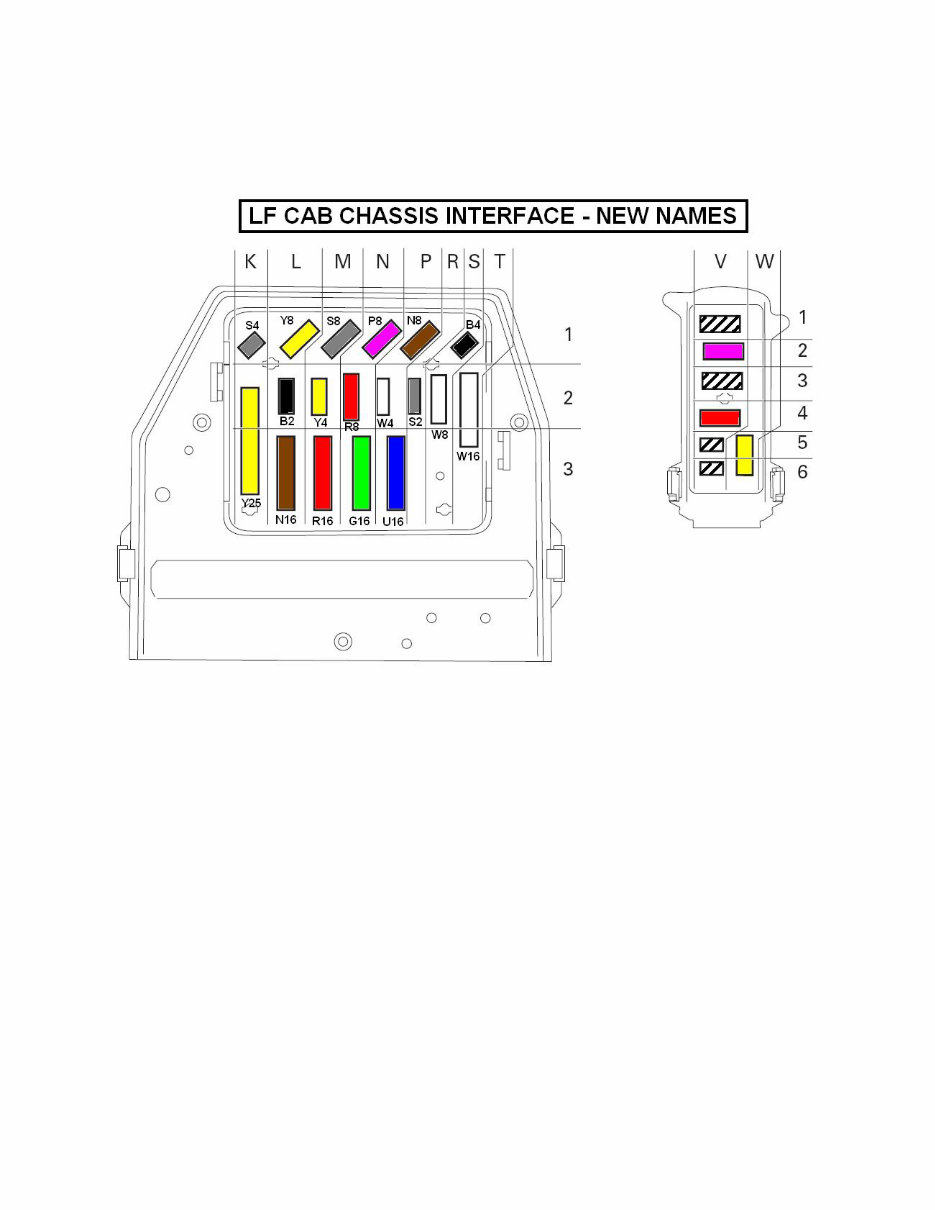
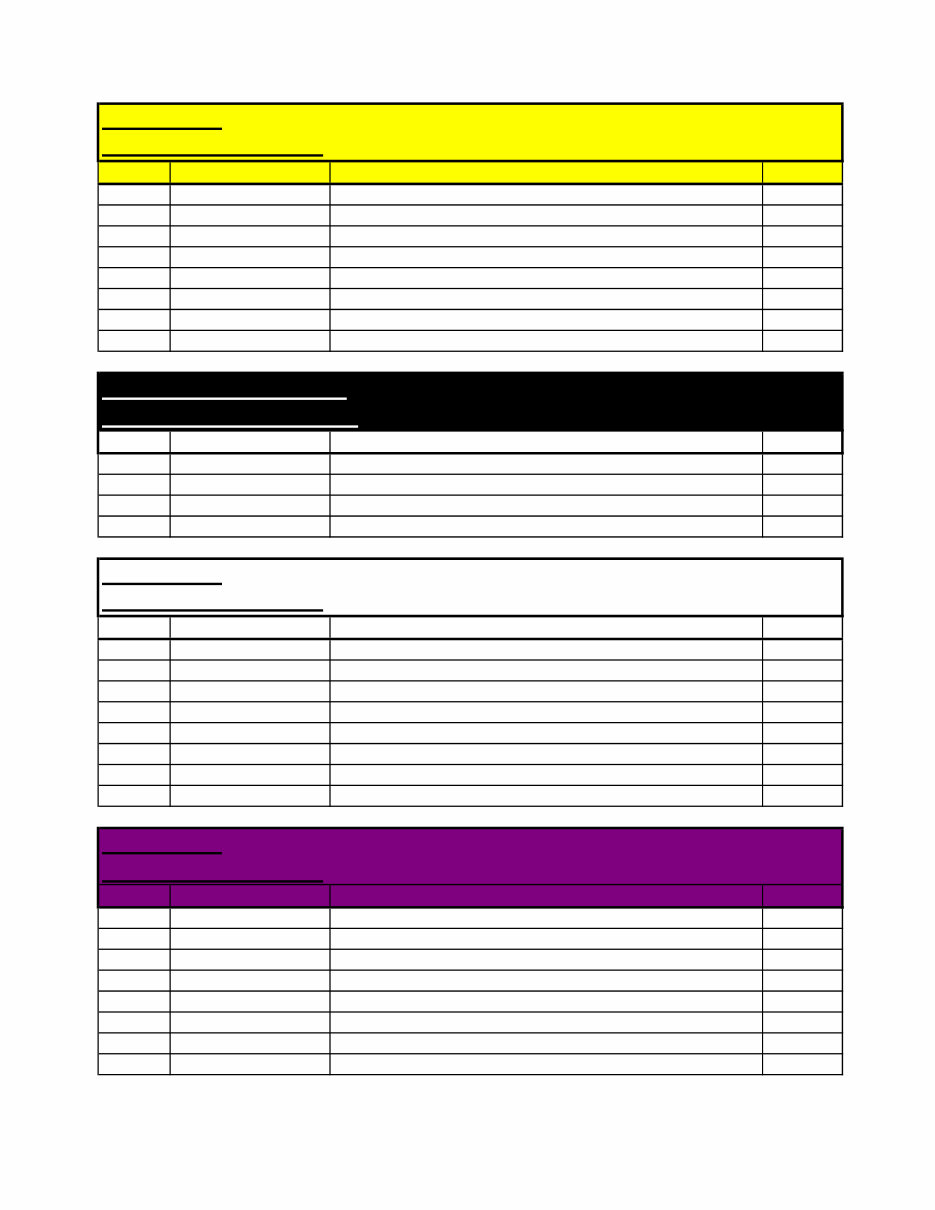
2007 Compliant Models 210 220 - Cab Chassis Interface Definition
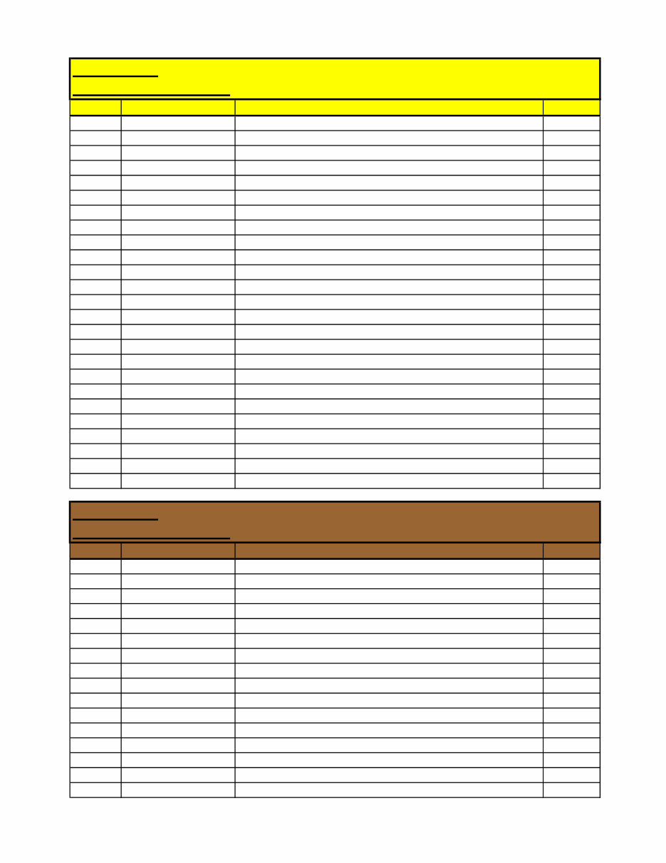
Connector: Yellow 25 pin
Connector Identifier: Y25
Pin No. Schematic page Function DAF no.
A1 M19A Fuel tank sender signal 3503
A2 M19AA Park brake 3402
A3 M05B Reverse Alarm (to buzzer) 5104
A4 M19C Diff lock solenoid 4517
A5 M01E Urea Heater (only if a design requirement) 1665
A6 M19C Brake wear 3406
A7 M05B Reverse light switch +ve - fuse 46 1217
A8 M05A Direction indicator LH truck 2036
A9 M05A Direction indicator RH truck 2037
A10 M04A Tail lamp LH 2170
A11 M04A Tail lamp RH 2169
A12 M04B Rear fog LH/RH 2152
A13 M05B Rear stop lamp LH/RH 4601
B1 M01D ABS trailer pin 2 and 24S trailer pin 6 +ve supply 1356
B2 M05B Reverse alarm from switch 4591
B3 M10A Battery supply +ve - Pin 4 Trailer Socket S 1110
B4 M03A Air drier +ve supply - ignition fuse F39 1240
B5 M03A Heated Sedimenter 5051
B6 M18A Alarm 3659
B7 M19A Direction indicator trailer LH - Pin 3 trailer socket N 2008
B8 M19A Direction indicator trailer RH - Pin 5 trailer socket N 2009
B9 M19C Diff lock switch 3408
B10 M15B ABS trailer warning light 3428
B11 M19AA Cab lock down 3412
B12 M10A Body light 2155
Connector: Brown 16 pin
Connector Identifier: N16
Pin No. Schematic page Function DAF no.
A1 M19A Air 2 transducer supply 3639
A2 M19A Air 1 transducer ground 3638A
A3 M19A Air 1 transducer supply 3639A
A4 M19A Air 1 transducer signal 3640
A5 M06A Tachograph sender -ve (pin 2 sender unit) 3020
A6 M06A Tachograph sender +ve (pin 1 sender unit) 3021
A7 M06A Tachograph sender signal 1 (pin 4 sender unit) 3018
A8 M06A Tachograph sender signal 2 (pin 3 sender unit) 3019
B1 M19A Gearbox protection solenoid range change 4030
B2 M18A Alarm 3660
B3 M19AA Gearbox neutral switch 4721
B4 M16A PTO solenoid output VIC 4596
B5 M03A W.I.F. warning light 5049
B6 N/C
B7 M19A Air 2 transducer ground 3638
B8 M19A Air 2 transducer signal 3641
(5/08) PM618018 Page 1 of 6
2007 Compliant Models 210 220 - Cab Chassis Interface Definition
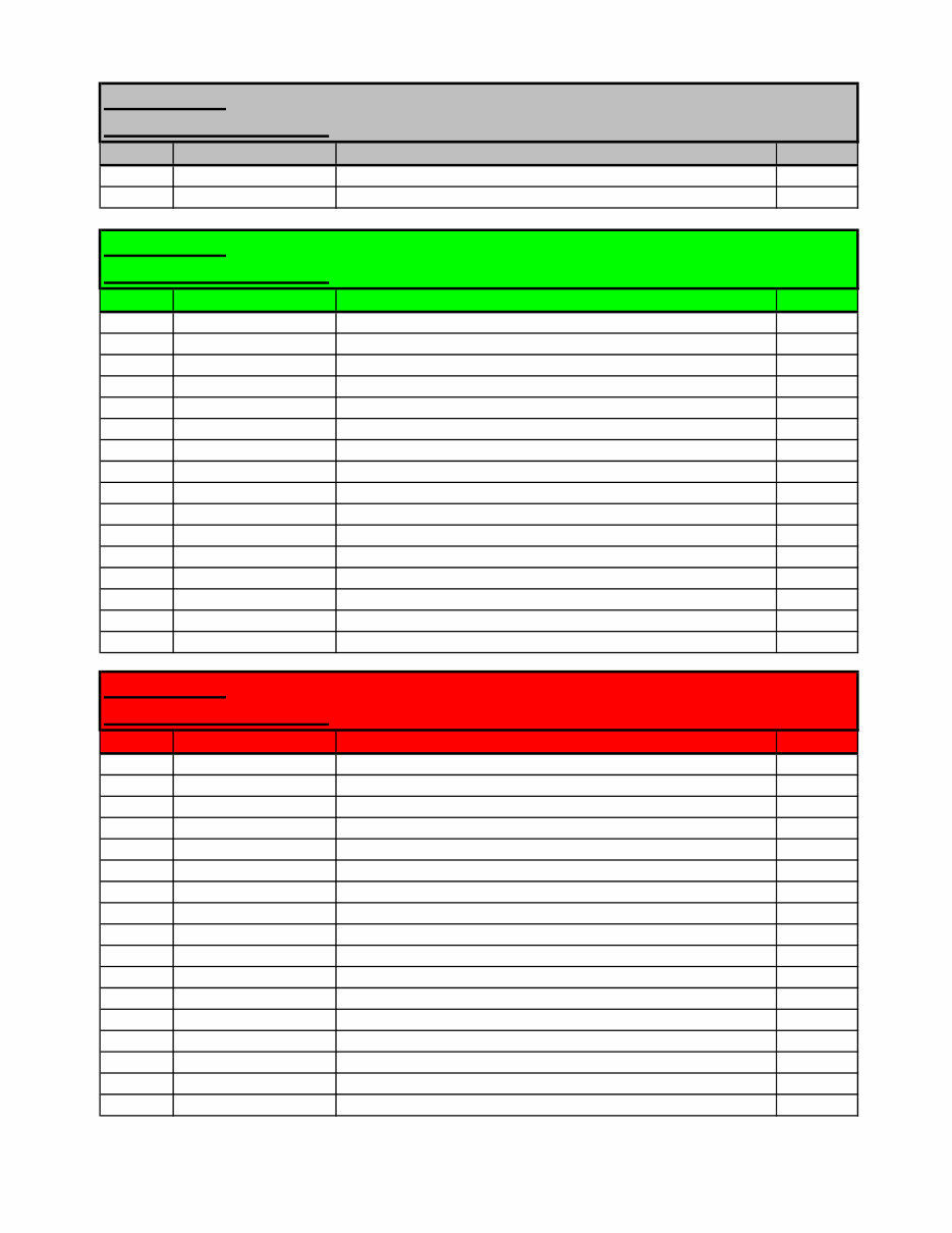
Connector: Grey 2 pin
Connector Identifier: S2
Pin No. Schematic page Function DAF no.
1 M02B Starter solenoid 4009
2 M15B Trailer ABS 1119
Connector: Green 16 pin
Connector Identifier: G16
Pin No. Schematic page Function DAF no.
A1 M04E Headlamp levelling pin 1 to motor 3 4953
A2 M04E Headlamp levelling pin 2 to motor 1 2169
A3 M04C Ground
A4 M04C Ground
A5 M04C Ground
A6 M04B Front Fog Lamps 2142
A7 M04C Front Driving Lamps 2122
A8 N/C
B1 M04B/BB Headlamp dip beam LH 2114
B2 M04B/BB Headlamp dip beam RH 2113
B3 M04B/BB Headlamp main beam LH 2122B
B4 M04B/BB Headlamp main beam RH 2122A
B5 M05A Horn 4535
B6 M04A Front side lamps LH & RH 2169
B7 M05A Direction indicator LH 2006
B8 M05A Direction indicator RH 2007
Connector: Red 16 pin
Connector Identifier: R16
Pin No. Schematic page Function DAF no.
A1 M20A/B/C/D ABS rear sensor LH - ecu pin 14 4629
A2 M20A/B/C/D ABS rear sensor LH - ecu pin 11 4628
A3 M20A/B/C/D ABS rear sensor RH - ecu pin 18 4631
A4 M20A/B/C/D ABS rear sensor RH - ecu pin 17 4630
A5 M20A/B/C/D ABS front sensor LH - ecu pin 15 4621
A6 M20A/B/C/D ABS front sensor LH - ecu pin 12 4620
A7 M20A/B/C/D ABS front sensor RH - ecu pin 13 4623
A8 M20A/B/C/D ABS front sensor RH - ecu pin 10 4622
B1 M20A/B/C/D ABS rear valve LH inlet - ecu pin 2 4641
B2 M20C/D ABS rear valve LH outlet - ecu pin 5 4640
B3 M20C/D ABS rear valve RH inlet - ecu pin 8 4643
B4 M20A/B/C/D ABS rear valve RH outlet - ecu pin 9 4642
B5 M20A/B/C/D ABS front valve LH inlet - ecu pin 3 4633
B6 M20B/C/D ABS front valve LH outlet - ecu pin 6 4632
B7 M20B/C/D ABS front valve RH inlet - ecu pin 1 4635
N/C
B8 M20A/B/C/D ABS front valve RH outlet - ecu pin 4 4634
(5/08) PM618018 Page 2 of 6
2007 Compliant Models 210 220 - Cab Chassis Interface Definition
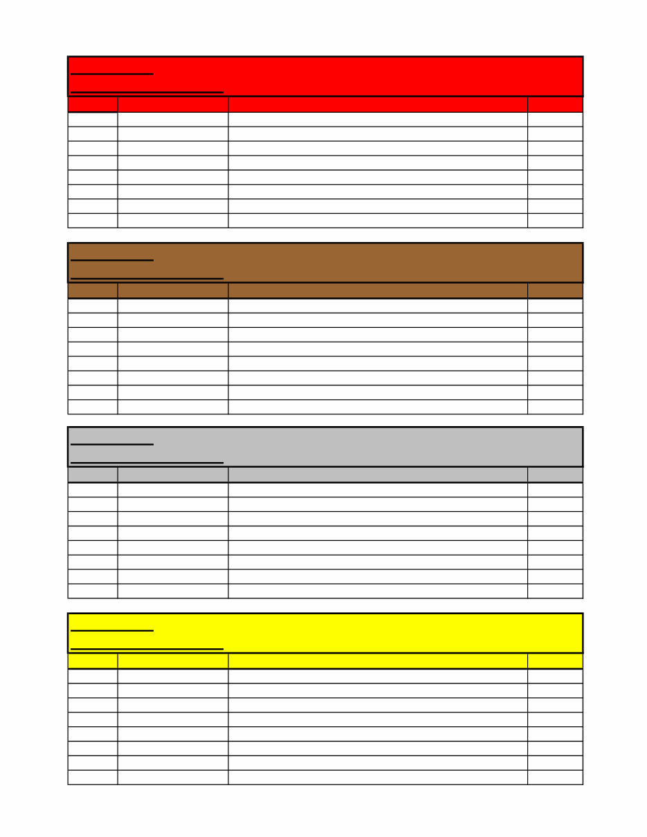
Connector: Red 8 pin
Connector Identifier: R8
Pin No. Schematic page Function DAF no.
1 M02A Isolation Switch - A5 1380
2 M02A Isolation Switch - A4 4179
3 M02A Battery isolation remote operation - A1 4176
4 M02A Battery isolation remote operation - A2 4177
5 M01CC Battery isolation before battery master isolation switch 1000
6 N/C
7 N/C
8 N/C
Connector: Brown 8 pin
Connector Identifier: N8
Pin No. Schematic page Function DAF no.
1 M27A CAN H - vcan 3701E
2 M27A CAN L - vcan 3700E
3 M01E Dosing Unit KL15 4265
4 M01E Dosing Unit KL30 1640
5 M27A Engine +ve supply fused battery 1177
6 M27A Engine +ve supply ignition 1211
7 M17B Air conditioning compressor +ve supply 5055
8 M01C Alternator W/L 1020
Connector: Grey 8 pin
Connector Identifier: S8
Pin No. Schematic page Function DAF no.
1 M30A Switch Wire - Dashboard X003
2 M30A Switch Wire - Dashboard X004
3 M30A Switch Wire - Dashboard X005
4 M30A Switch Wire - Dashboard X006
5 M30A Switch Wire - Headershelf X007
6 M30A Switch Wire - Headershelf X008
7 M30A Switch Wire - Headershelf X009
8 M30A Switch Wire - Headershelf X010
Connector: Yellow 8 p Allison Gearbox MD3060
Connector Identifier: Y8
Pin No. Schematic page Function DAF no.
1 M25B KL30 supply - Automatic/Automated Gearbox 1163
2 M25B KL15 supply - Automatic/Automated Gearbox 1302
3 M25B Ground
4 M25B Allison Selector Direction Sense 5728
5 M25B MD3060 AGC Pin 43 4595
6 M25B MD3060 AGC Pin 30 5701
7 M25B MD3060 AGC Pin 1 & 17 5646
8 M25B MD3060 AGC Pin 45 5649
(5/08) PM618018 Page 3 of 6
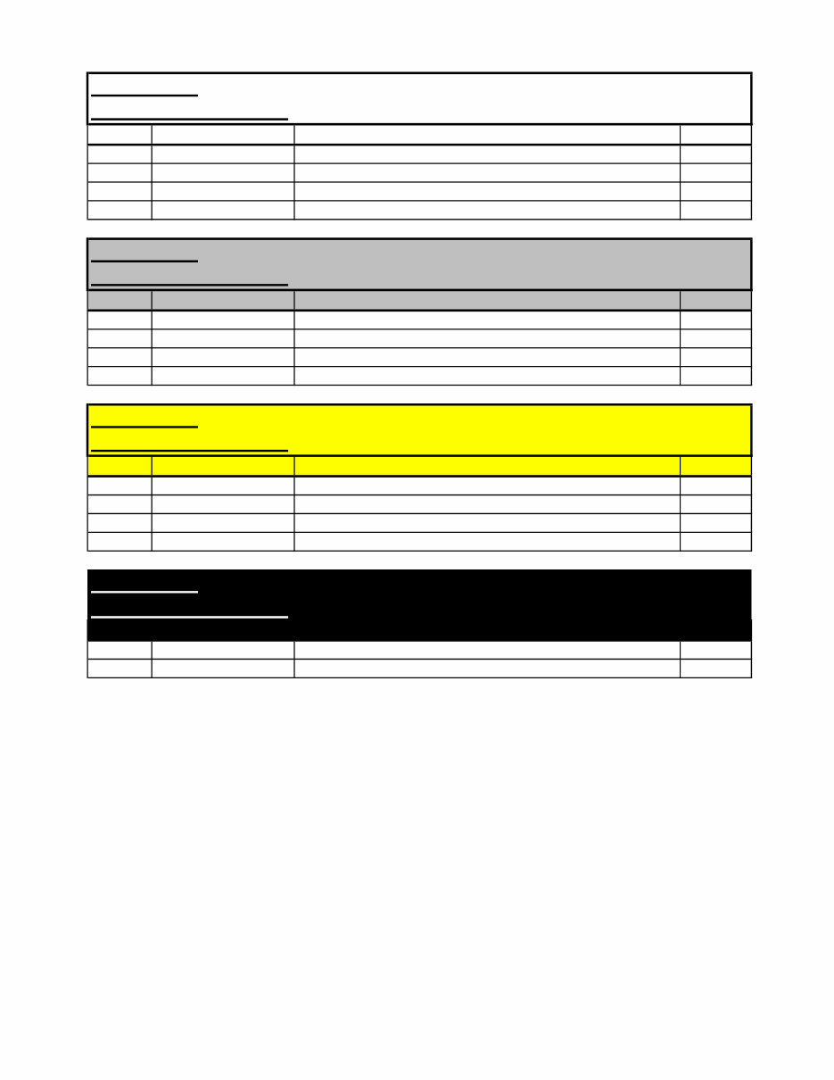
2007 Compliant Models 210 220 - Cab Chassis Interface Definition
Connector: Yellow 8 p Allison 1000/2000 - AsTronic Lite
Connector Identifier: Y8
Pin No. Schematic page Function DAF no.
1 M25A/C KL30 supply - Automatic/Automated Gearbox 1163
2 M25A/C KL15 supply - Automatic/Automated Gearbox 1302
3 M25A/C Ground
4 N/C
5 M25C AsTronic gearbox module - ZF CAN - A5 3731
6 M25C AsTronic gearbox module - ZF CAN - A2 3732
7 N/C
8 N/C
Connector: Black 4 pin
Connector Identifier: B4
Pin No. Schematic page Function DAF no.
1 M17C Auxiliary Cab Heater Pump 4935
2 M17C Auxiliary Cab Heater Pump 4936
3 N/C
4 N/C
Connector: White 8 pin
Connector Identifier: W8
Pin No. Schematic page Function DAF no.
1 M27A Throttle pedal +ve supply - engine ecu pin J2-22 4677
2 M27A Throttle pedal signal - engine ecu pin J2-9 4679
3 M27A Throttle pedal common - engine ecu J2-23 4678
4 M27A Throttle pedal on-idle switch - engine ecu pin J2-11 4681
5 M27A Throttle pedal off-idle switch - engine ecu pin J2-1 4166
6 M27A Throttle pedal idle common - engine ecu pin J2-34 4680
7 N/C
8 M02A Grid Heater Warning 4014
Connector: Purple 8 pin
Connector Identifier: P8
Pin No. Schematic page Function DAF no.
1 M28A/AA ECAS height sensor RH - ecu pin 7 4736
2 M28A/AA ECAS height sensor LH - ecu pin 19 4739
3 M28A/AA ECAS height sensor common - ecu pin 18 9009
4 M28A/AA ECAS valve RH - ecu pin 20 4742
5 M28A/AA ECAS valve LH - ecu pin 8 4741
6 M28A/AA ECAS valve exhaust - ecu pin 21 4740
7 N/C
8 N/C
(5/08) PM618018 Page 4 of 6
2007 Compliant Models 210 220 - Cab Chassis Interface Definition
Connector: White 4 pin
Connector Identifier: P4
Pin No. Schematic page Function DAF no.
1 M18A Alarm Siren Pin 3 1229
2 M18A Alarm Siren Pin 2 3653
3 M18A Alarm Siren Pin 1 GROUND
4 N/C
Connector: Grey 4 pin
Connector Identifier: S4
Pin No. Schematic page Function DAF no.
1 M11A Windscreen washer pump 5161
2 M11A Ground
3 Headlamp wash pump (not required at present)
4 N/C
Connector: Yellow 4 pin
Connector Identifier: Y4
Pin No. Schematic page Function DAF no.
1 M20C ASR valve - ecu pin 7 4578
2 M20C ASR valve - ecu pin 16 5060
3 N/C
4 N/C
Connector: Black 2 pin
Connector Identifier: B2
Pin No. Schematic page Function DAF no.
1 N/C
2 N/C
(5/08) PM618018 Page 5 of 6
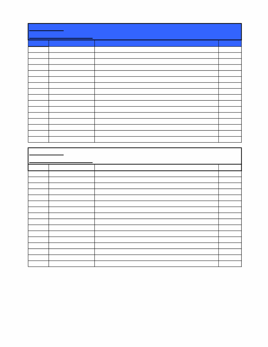
2007 Compliant Models 210 220 - Cab Chassis Interface Definition
Connector: Blue 16 pin
Connector Identifier: U16
Pin No. Schematic page Function DAF no.
A1 N/C
A2 N/C
A3 N/C
A4 N/C
A5 N/C
A6 N/C
A7 N/C
A8 N/C
B1 N/C
B2 N/C
B3 N/C
B4 N/C
B5 N/C
B6 N/C
B7 N/C
B8 N/C
Connector: White 16 pin
Connector Identifier: W16
Pin No. Schematic page Function DAF no.
A1 M22A FAN 'Stop' Lamp 3725
A2 M10A PTO status 3524
A3 M22A FAN 'Warning' Lamp 3726
A4 M30A Engine Running 3003
A5 M30A FAN K-Line 3646
A6 M30A Remote PTO 3420
A7 M30A Ignition Control Fuse - F35 2161
A8 M30A Cab lock down 3412
B1 M30A Ground
B2 M30A Ground
B3 M30A Enable ESC 3143
B4 M30A N1 ESC 3144
B5 M30A N2 ESC 3145
B6 M30A N3 ESC 3146
B7 M06A Tachograph speed signal B7 3514
B8 M30A Battery Control Fuse - F50 1600
(5/08) PM618018 Page 6 of 6

Electrical Schematics for Model 210 and 220
The content of the pages identified below is generic and not specific to Model 210/220 built after
January 1, 2008. When working on the vehicle it is likely that terminated harnesses will be
encountered where either an available option has not been specified or a feature is not available on
the vehicle.
Page No. System/Component
M00 Electrical schematic information
M01C Supply battery
M01CC Supply battery (with isolator)
M01D Supply fuses
M01E Supply fuses (additional)
M02A Grid heater / remote battery isolator
M02B Starter
M03A Heated sedimenter / Air drier / WIF (water in fuel)
M04A Lighting
M04B R. fog / F. fog / Main / Dip beam
M04BB R. fog / Main / Dip beam
M04C Driving lamps
M04D Daytime running lamps
M04E Headlamp levelling
M05A Horn / Indicators
M05B Stop / Reverse lights
M05C Rotating beacons
PM618018

M06A Tachograph / Speedo
M07A Diagnostics
M08B Central locking
M08C Electric windows / sun roof
M09A LHD heated & steerable mirrors
M09B RHD heated & steerable mirrors
M10A Interior & body light
M11A Wiper, wash circuit
M14A Accessories LHD
M14AA Accessories RHD
M14B Heated wind screen / seat
M15A Trailer connections
M15B Trailer ABS
M16A Power Take Off
M17B Heater & aircon
M17C Auxiliary cab heater
M18A Alarm
M18B Immobiliser
M19A VIC
M19AA VIC (continued)
M19B DIP / MMI (MCS)
PM618018

M19C Brake wear / Diff lock
M19D BBM
M20A ABS version E 4S2M
M20B ABS version E 4S3M
M20C ABS / ASR version E
M20D ABS version E 4S4M
M21A Telephone
M22A FAN model
M23A Steering wheel (without air bag)
M23BAA Steering wheel (With air bag)
M24A Air bag / Pre-belt tensioner
M25A Allison 2100 Auto gearbox
M25B Allison 3000 Auto gearbox
M25C ZF As-Tronic gearbox
M27A Engine ECU CM2150
M28A ECAS (dual sensor)
M28AA ECAS (single sensor)
M30A Additional wiring
M31A Regeneration
PM618018
You're Reading a Preview
What's Included?
Fast Download Speeds
Online & Offline Access
Access PDF Contents & Bookmarks
Full Search Facility
Print one or all pages of your manual
$61.99
Viewed 89 Times Today


Secure transaction
What's Included?
Fast Download Speeds
Online & Offline Access
Access PDF Contents & Bookmarks
Full Search Facility
Print one or all pages of your manual
$61.99
Our digital manuals provide comprehensive electrical schematics for 2007 and 2008 compliant models 210 and 220. These manuals are invaluable resources for professional mechanics and DIY enthusiasts alike. Whether you're troubleshooting electrical issues or planning modifications, these manuals offer detailed diagrams to assist you in your car repair endeavors.


