CONTENTS MAINTENANCE PERIODIC MAINTENANCE SCHEDULES .................................. MA-1- 1 MAINTENANCE INTERVALS .... MA-1- 1 DAILY MAINTENANCE .................. MA-2- 1 EMISSION CONTROL SYSTEM MAINTENANCE .............................. MA-3- 1 NOISE CONTROL SYSTEM MAINTENANCE ........................... MA-3- 1 ENGINE MAINTENANCE PROCEDURE .................................. MA-4- 1 BEFORE PERFORMING MAINTENANCE ........................... MA-4- 1 BASIC MECHANICAL SYSTEM ..................................... MA-4- 2 COOLING SYSTEM .................... MA-4-10 LUBRICATION SYSTEM ............ MA-4-15 FUEL SYSTEM ........................... MA-4-22 INTAKE AND EXHAUST SYSTEM ..................................... MA-4-28 OTHERS...................................... MA-4-29 CHASSIS MAINTENANCE PROCEDURE .................................. MA-5- 1 AUTOMATIC TRANSMISSION ....................... MA-5- 1 PROPELLER SHAFT ................ MA-5- 2 STEERING SYSTEM .................. MA-5- 3 AXLE AND WHEEL .................... MA-5- 5 TIRE AND WHEEL ..................... MA-5- 8 BRAKE SYSTEM ......................... MA-5-11 PARKING BRAKE ....................... MA-5-14 SUSPENSION ............................ MA-5-14 OTHERS ..................................... MA-5-16 MAINTENANCE SERVICE DATA ................................................ MA-6- 1 MA MA-0-1
PERIODIC MAINTENANCE SCHEDULES PERIODIC MAINTENANCE SCHEDULES MAINTENANCE INTERVALS NOTE The maintenance or lubrication services shown below are to be performed at the indicated intervals (miles or months, whichever occurs first). Items indicated by “♦” should be performed only by your authorized UD dealer or qualified ser- vice facility. For other items, the maintenance procedures are given in this chapter. Items marked with “*” are related to the EMISSION CONTROL SYSTEM MAINTENANCE. Under the following severe operating conditions, more frequent servicing will be required. – Operation in heavy dust conditions – Operation at extremely low or high ambient temperature – Extended high-speed operation with vehicle fully-loaded to its GVWR – Extended low-speed operation – Frequent stop-and-go operation Any replacement parts used for required maintenance service or repairs should be genuine UD parts or equivalent in quality and design to genuine UD parts. Abbreviations: I = Inspect, clean and correct or replace as necessary. T = Tighten to specified torque A = Check and adjust if necessary L = Lubricate R = Replace or change MA-1-1
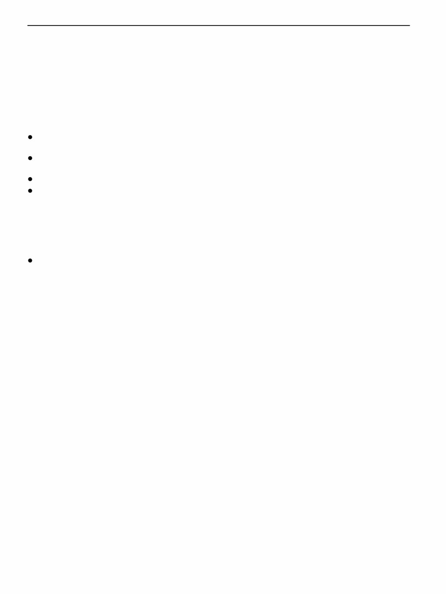
PERIODIC MAINTENANCE SCHEDULES NOTE All illustrations in this manual are based on UD recommended tools. Tool shapes may differ from SPX Corporation tools. Tool name and number (SPX Corporation No.) Description Shape Feeler gauge 99541 Z5000 ( – ) For adjusting valve clearance Thickness mm (in): 0.25 (0.0098), 0.3 (0.012), 0.35 (0.0138), 0.4 (0.016), 0.45 (0.0177), 0.5 (0.020) Compression gauge adpter (A) 99640 Z5004 ( J-47230 ) For measuring compression pressure Compression gauge adpter (B) 99640 Z5005 ( – ) 99640 Z5006 ( – ) For measuring compression pressure The compression gauge adpter (B) is used with the compression gauge adpter (A) MA-1-2
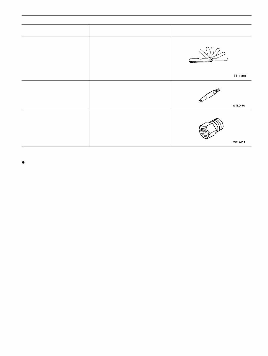
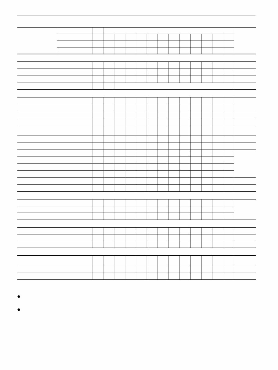
PERIODIC MAINTENANCE SCHEDULES ENGINE Items First Every Months (every) Reference page Miles x 1,000 3 6 9 10 12 15 18 20 24 30 36 50 72 Kilometers x 1,000 5 10 15 16 20 25 30 32 40 50 60 80 120 BASIC MECHANICAL SYSTEM ♦ Valve clearance A 24 MA-4-2 ♦*Cylinder compression pressure A 36 MA-4-7 ♦*Engine mounting A 36 FUEL SYSTEM ♦ Low and High idle speed A *Fuel filter R 6 MA-4-24 Fuel hose and pipe (Fuel filter to supply pump, Fuel tank to fuel filter, Engine to fuel tank) A R R:36 MA-4-27 LUBLICATION SYSTEM *Engine oil and oil filter Type1 R R 6 MA-4-15 (With UDXtra Engine oil) Type2 R R 6 *Engine oil and oil filter Type1 R R 2 (With non UDXtra Engine oil) Type2 R R 2 Type 1/Type2: For type of operation details refer to page MA-4-15 COOLING SYSTEM *Cooling fan I 12 MA-4-10 *Drive belts Initial inspection at first 6,000 miles (10,000 km) MA-4-8 R 12 Engine coolant R: Every 185,000 miles (300,000 km) 24 MA-4-13 *Radiator and heater hoses and clamps A 12 MA-4-10 INTAKE AND EXHAUST SYSTEM *Air cleaner element R 12 MA-4-28 Intake air hose and clamps R 24 MA-4-29 *Intercooler body I 6 MA-4-12 ♦*Intercooler hoses I 24 ♦ Turbo charger rotor operation I 24 Exhaust tubing and muffler attachment loose and damage A 12 MA-4-29 ELECTRICAL EQUIPMENT ♦ Starter bearing grease I 12 MA-4-29 ♦ Starter brush I 24 MA-4-29 MA-1-3
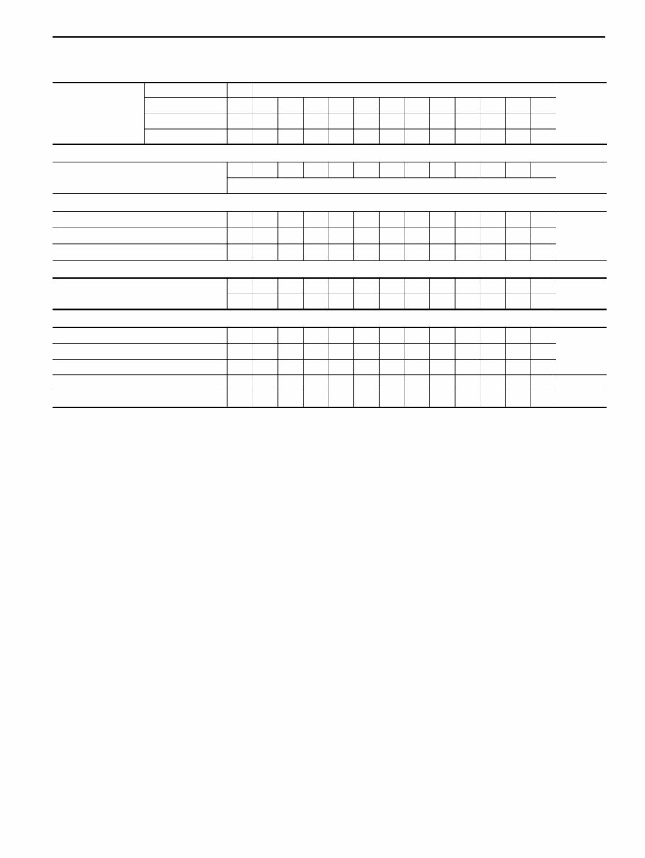
PERIODIC MAINTENANCE SCHEDULES CHASSIS Items First Every Reference page Miles x 1,000 3 6 9 10 12 15 18 20 24 30 36 50 72 Kilometers x 1,000 5 10 15 16 20 25 30 32 40 50 60 80 120 Months (every) 1 2 4 6 8 10 12 AUTOMATIC TRANSMISSION Automatic transmission fluid I MA-5-1 R: Every 25,000 miles (40,000 km) PROPELLER SHAFT ♦ Universal joint I I MA-5-3 ♦ Center bearing I I ♦ Condition of propeller shaft I I DIFFERENTIAL Differential gear oil I MA-5-7 R STEERING SYSTEM ♦ Gear box I I MA-5-4 Steering wheel free play I Power steering system fluid I ♦ Steering linkage I I MA-5-5 ♦ Steering fluid piping I MA-5-4 MA-1-4
PERIODIC MAINTENANCE SCHEDULES NOTE 1. Perform maintenance after the first 1,000 miles (1,600 km) of operation. This maintenance procedure also applies whenever a tire is replaced. 2. During periods of severe service operation or frequent stop-and-go operation, more frequent inspections of the brake system should be performed. Items First Every Reference page Miles x 1,000 3 6 9 10 12 15 18 20 24 30 36 50 72 Kilometers x 1,000 5 10 15 16 20 25 30 32 40 50 60 80 120 Months (every) 1 2 4 6 8 10 12 AXLE AND WHEEL ♦ Front axle (I-beam) I I MA-5-5 ♦ Rear axle housing I I MA-5-7 ♦ Front wheel bearing grease R Wheel nut (Refer to note 1.) I Initial inspection at first 1,000 miles (1,600 km) MA-5-11 BRAKE SYSTEM ♦ Brake piping I MA5-12 ♦ Brake hose R ♦ Wheel cylinder repair kit R Brake fluid I R MA-5-11 ♦ Brake lining clearance (Refer to note 2.) I MA-5-12 ♦ Brake lining I MA-5-13 ♦ Brake drum I MA-5-13 ♦ Parking brake lever stroke I I MA-5-14 ♦ Parking brake lining clearance I ♦ Parking brake lining I ♦ Parking brake drum I ♦ Master cylinder repair kit R ♦ Check valve I MA-5-13 SUSPENSION Leaf spring I I MA-5-15 Shock absorber I I ♦ U-bolt and nut I I ELECTRICAL SYSTEM Battery electrolyte level I Battery terminal I Specific gravity of battery electrolyte I OTHERS Tire and wheel rotation Ro- tate MA-5-16 ♦ Acoustical shielding I Grease lubrication point L MA-1-6 MA-1-5
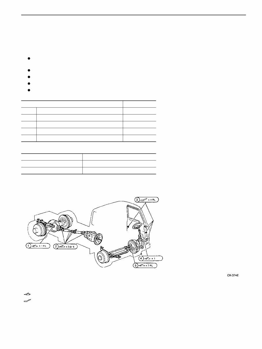
PERIODIC MAINTENANCE SCHEDULES AUTOMATIC TRANSMISSION MAINTENANCE SCHEDULE Change the automatic transmission fluid every 40,000 km (25,000 miles) under normal operating conditions. If the vehicle is mainly operated under one or more of the following conditions, change the fluid every 20,000 km (12,500 miles). Extended idling and/or low-speed operation in stop-and- go traffic Uses such as delivery or other commercial service In hilly or mountainous terrain Frequent trailer pulling Extremely dusty/dirty conditions GREASE LUBRICATION POINTS Recommended lubricants : Lubricate with a grease gun. : Apply grease manually with a stick. Do not apply with finger or hand. RL : Lubrication points located on both left and right sides of vehicle. X2 : Number of grease nipples or points. * : Refer to enlarged view. Lubrication point No. of points (1) Rear spring pin 1RL (2) Propeller shaft journal & yoke 3 or 5 (3) Door hinge, locks and latch 4RL (4) Steering column 1 (5) King Pin 2RL Specifications Parts NLGI No. 1 (3) NLGI No. 2 or NLGI No. 3 (1),(2),(4),(5) MA-1-6
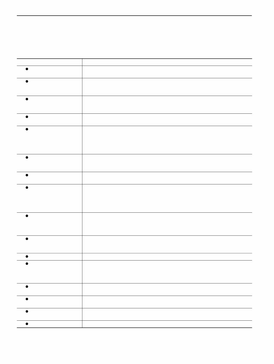
DAILY MAINTENANCE DAILY MAINTENANCE Daily maintenance should be performed by the driver before or after the day’s operation in order to assure safe driving and prevent problems on the road. If a problem with any part of the vehicle is noticed during daily inspection, it should be repaired immediately. Consult your authorized UD dealer or qualified service facility for repairs. Item Check points Drive belt Check for belt tension, wear or cracks. If required, replace the belt. Refer to page MA-4-8 for the procedures. Engine oil leakage and oil level Check for oil leakage from engine. Also check for traces of oil on the road directly under the engine. Check oil level and contamination. Refer to page MA-4-17 for the procedures. Coolant leakage and coolant level Check for leakage from engine. Also check for traces of water on the road directly under the engine. If leakage is noticed, check the coolant level. Refer to page MA-4-10 for the procedures. Water hoses and clamps Check all radiator and heater hose clamps for tightness. Inspect all hoses; if they are swollen, cracked or otherwise worn, replace them. Sedimentor Check for water accumulation. Drain water from the sedimentor before water reaches the upper portion of the water sensor installed in the transparent lower portion of the sedimentor case. When water has accumulated in the sedimentor, it has also accumu- lated in the fuel tank. Drain water from fuel tank when the sedimentor is drained. Refer to page MA-4-25 for the procedures. Fuel leakage and fuel quantity Check for leakage from engine. Also check for traces of fuel on the road directly under the engine. Check the amount of fuel using the fuel gauge. It is advisable to keep the fuel tank full. Starting ability and noise Check engine for smooth starting. If engine operation is erratic or noisy, immediately stop and check the cause of the problem. Oil, fluid, fuel, grease and air leakage Check the transmission and differential, brake system, clutch system, power steering system and fuel system for leakage of oil, fluid, fuel, grease and/or air. Fuel and air leakage is sometimes hard to detect so careful checks are needed. Leakage may be present only when the engine/vehicle is in operation. If leakage is noticed, check the level of oil/fluid/coolant, repair the leaking point and correct the level as necessary. Front wheel alignment If abnormal tire wear or ride and handling characteristics such as vehicle lead or wan- der are experienced with properly inflated tires, the front wheel alignment should be checked. Refer to page MA-5-5 for the procedures. Wheel nut Check all wheel nuts for proper tightness. If any nut is missing or loose, check that all wheel nuts are tightened to the specified torque. Refer to page MA-5-11 for the procedures. Disc wheel Check for deformity, cracks or damage. Tire Check the air pressure using a tire gauge. Note that air pressure differs between the allowable load capacities of tires. Also check tread depth and for cracks or foreign matter caught in grooves. Refer to page MA-5-9 for the procedures. Service brake operation Ensure the BRAKE warning light remains off when the parking brake lever is released. Next, drive the vehicle at low speed and check for braking performance. Parking brake operation Apply the parking brake on an upgrade. Ensure the BRAKE warning light illuminates with the key switch ON and that the brake firmly operates. Lighting and signal sys- tem Turn all switches of the lighting and signal system ON and OFF to ensure headlights, turn signal lights, etc. operate properly. Clean dirty light lenses. Horn Operate the horn button to ensure the horn sounds. MA-2-1
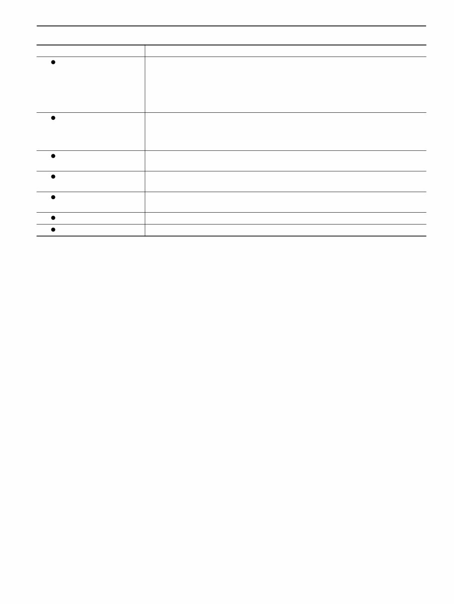
DAILY MAINTENANCE Item Check points Meters, indicator light and warning light Check cluster meters (such as the air pressure gauge and water temperature gauge), to ensure they register the specified ranges. The water temperature gauge should be checked after warming up the engine sufficiently or while the vehicle is being driven. Also check the indicator light for proper operation in response to the operation of the corresponding control. Check that warning lights remain off while the engine is in operation. Windshield wiper and washer Operate the wiper and washer switches to ensure the windshield wiper and washer operate. Check the level of washer fluid and add fluid as necessary. If the wiper does not wipe the windshield sufficiently or does not contact the windshield well, the wiper blades need to be replaced. Mirror and front wind- shield Check mirrors for proper angle of view, damage and cleanliness; clean if dirty and replace if damaged. Check the windshield for cleanliness; clean if dirty. Heater defroster Operate the car heater to check the condition of hot-air discharge from the defroster. This check should be carefully performed especially in rainy weather. Seat belt Fasten the seat belt to check for proper operation of the buckle. Also check the belt for damage. Door lock Check door locks for proper operation. Cab tilt lock mechanism Check the condition and operation of the cab tilt lock mechanism. MA-2-2
EMISSIONS CONTROL SYSTEMS MAINTENANCE EMISSIONS CONTROL SYSTEMS MAINTENANCE To maintain efficient emissions control systems operation, have the EMISSION CONTROL SYSTEM MAINTE- NANCE as shown in the VEHICLE SERVICE AND MAINTENANCE chapter of this manual performed at the intervals indicated. CAUTION Do not modify, alter, disconnect or remove any part of the vehicle which could affect, directly or indirectly, vehicle emissions. Do not operate your vehicle if you notice engine misfire, a significant loss of performance or other improper operation. Consult your UD dealer or other qualified service facility for service. NOISE CONTROL SYSTEM MAINTENANCE To help assure noise control system integrity, the maintenance services shown in the following chart must be performed at the intervals indicated. When inspecting the exhaust system confirm that all components are intact and securely fitted. Also check all exhaust system components for holes, leaks and corrosion. Do not perform any prohibited act to the noise control system as described in the following chart. TAMPERIMG WITH NOISE CONTROL SYSTEM PROHIBITED Federal law prohibits the following acts or the causing thereof: (1) The removal or rendering inoperative by any person other than for purposes of maintenance, repair, or replacement, of any device or element of design incorporated into any new vehicle for the purpose of noise control prior to its sale or delivery to the ultimate purchaser or while it is in use, or (2) the use of the vehicle after such device or element of design has been removed or rendered inoperative by any parson. Among those acts presumed to constitute tampering are the acts listed below. Control System Prohibited Acts Air Intake System Removal or rendering inoperative air cleaner, intake resonator or intake duct, and piping. Acoustical Shielding Removal of cab shields or acoustical insulation. Removal of engine enclosures. Cooling System Removal or rendering inoperative fan clutch. Removal of fan shrouds or radiator side shields. Engine and Drive Line System Removal or rendering engine speed governor inoperative so as to allow engine speed to exceed manufacturer specifications. Exhaust System Removal or rendering inoperative exhaust system components including muf- fler, pipe shield or piping. MA-3-1
2005-2007 Nissan Diesel (UD Trucks) 1300/1400 Trucks Service & Repair Manual is a comprehensive resource covering a wide range of technical aspects related to the maintenance and repair of these Nissan Diesel (UD Trucks) models. This manual is designed to assist both professional mechanics and DIY enthusiasts in performing various tasks.
01 GENERAL
02 MAINTENANCE & LUBRICATION
03 TROUBLE DIAGNOSIS
04 ENGINE
05 CHASSIS
With a total of 1164 pages, this manual provides detailed technical information in English. It is available in PDF format and is compatible with a wide range of operating systems including Win95/98/ME/XP/Vista/7, Linux, and MAC.
Our collection features a variety of Repair Manuals, Service Manuals, and Workshop Manuals for Cars, Trucks, Industrial Equipment, Heavy Equipment, and more. These manuals cover a diverse range of brands for cars and motorcycles.
Key benefits include instant access, elimination of shipping costs, and immediate availability without the delay of physical media. For any inquiries or assistance, please contact our customer support via the Contact Seller link. We are committed to sourcing the required manual if it is not readily available.