
")
2002-2004 Mitsubishi Fuso Truck FE FG FH FK FM Series Service Repair Factory Manual INSTANT (2002 2003 2004)
What's Included?
Fast Download Speeds
Online & Offline Access
Access PDF Contents & Bookmarks
Full Search Facility
Print one or all pages of your manual

SERVICE MANUAL
2002 Model
FOREWORD
This Service Manual contains maintenance and repair
methods for the Mitsubishi Fuso Truck FE, FG Series.
Read this manual carefully as an aid in providing correct,
efficient maintenance. Please note that the information
and specifications contained within this manual may
change without notice. This is due to product modifications
and contined vehicle improvements that are made
throughout the model years. Should you encounter any
discrepancy in the information provided, please do not
hesitate to contact your nearest Mitsubishi Fuso Dealer or
Mitsubishi Fuso Truck of America, Inc.
April 2001
GROUP INDEX
HOW TO READ THIS MANUAL
GENERAL .............................................
00
MAINTENANCE SCHEDULE ...............
01
ENGINE
< 4M5 > ................................................... 11A
< 4D3 > .................................................... 11B
LUBRICATION
< 4M5 > ................................................... 12A
< 4D3 > .................................................... 12B
FUEL AND ENGINE CONTROL
< 4M5 > ................................................... 13A
< 4D3 > .................................................... 13B
ELECTRONICALLY CONTROLLED
FUEL SYSTEM
< 4M5 > ................................................... 13EA
< 4D3 > .................................................... 13EB
COOLING
< 4M5 > ................................................... 14A
< 4D3 > .................................................... 14B
INTAKE AND EXHAUST
< 4M5 > ................................................... 15A
< 4D3 > .................................................... 15B
CLUTCH ...............................................
21
MANUAL TRANSMISSION ..................
22
AUTOMATIC TRANSMISSION ............
23
TRANSFER ........................................... 24
PROPELLER SHAFT ...........................
25
FRONT AXLE
< FE > ...................................................... 26A
< FG > ..................................................... 26B
REAR AXLE .........................................
27
WHEEL AND TIRE ...............................
31
FRONT SUSPENSION .........................
33
REAR SUSPENSION ...........................
34
BRAKE .................................................
35A
ANTI-LOCK BRAKE SYSTEM ............. 35E
PARKING BRAKE ................................
36
STEERING ............................................
37
FRAME .................................................
41
CAB ......................................................
42
ELECTRICAL .......................................
54
AIR-CONDITIONER ..............................
55A
HEATER ............................................... 55B
How to Read this Manual
Pub No. TWSE0101-H

INDEX
HOW THIS MANUAL IS STRUCTURED ................................................. 2
TERMS ................................................................................................... 15
2
23915
23929
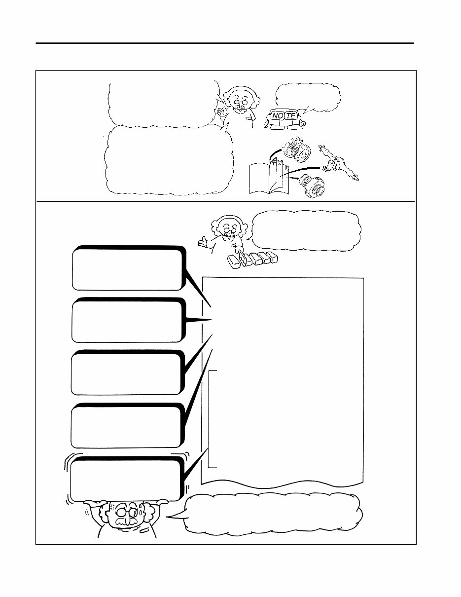
I'm here to explain how to use
this manual. To get the most out
of your manual, follow along
carefully and read all the notes
given by my assistant.
This manual is divided into groups,
with one group for each main area of
the vehicle.
By way of example, let's look at
Group 21, which covers the clutch.
We're here
to help you.
Group 21
Group 27
Group 31
Each group is divided into
five parts, as shown
below.
Specifications
Specifications, oil quantities, and
other information pertaining to
system components.
Structure and Operation
Information on the structure and
operation of the overall system
and its components.
Troubleshooting
An item-by-item guide to fault
symptoms and their probable
causes.
On-Vehicle Inspection and
Adjustment
Instructions for on-vehicle inspec-
tion and adjustment operations.
Service Instructions
(See the next and subsequent
pages.)
The service instructions are the most important
parts of this manual. Starting on the next page,
you'll learn more about them.
INDEX
SPECIFICATIONS ..........................................................
STRUCTURE AND OPERATION ...................................
TROUBLESHOOTING ...................................................
ON-VEHICLE INSPECTION AND ADJUSTMENT
1. Clutch Fluid Replacement and Air Bleeding
...................
2. Inspection of Clutch Booster Functionality
.....................
3. Clutch Pedal Play
...............................................................
CLUTCH PEDAL ............................................................
CLUTCH MASTER CYLINDER ......................................
CLUTCH BOOSTER AND CLUTCH MASTER
CYLINDER ......................................................................
CLUTCH POWER CYLINDER ........................................
CLUTCH-PROPER ........................................................
CLUTCH HOUSING .......................................................
CLUTCH DISC WEAR INDICATOR SWITCH .................
23916
23917
HOW THIS MANUAL IS STRUCTURED
3
Now, let's take a
detailed look at the
service instructions.
Please follow along
carefully.
23918
26310
20244
INDEX
SPECIFICATIONS .................................................
ON-VEHICLE INSPECTION AND ADJUSTMENT
1. Clutch Fluid Replacement and Air Bleeding ........
2. Inspection of Clutch Booster Functionality .........
3. Clutch Pedal Play ...................................................
CLUTCH PEDAL ...................................................
CLUTCH MASTER CYLINDER .............................
CLUTCH BOOSTER AND CLUTCH MASTER
CYLINDER .............................................................
CLUTCH POWER CYLINDER ..............................
CLUTCH-PROPER ................................................
CLUTCH HOUSING ..............................................
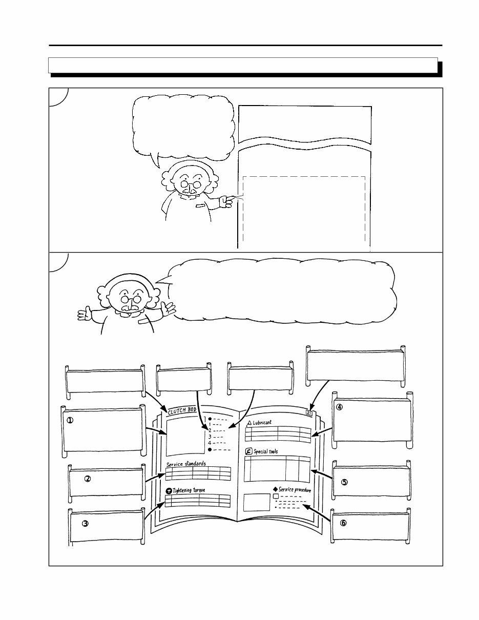
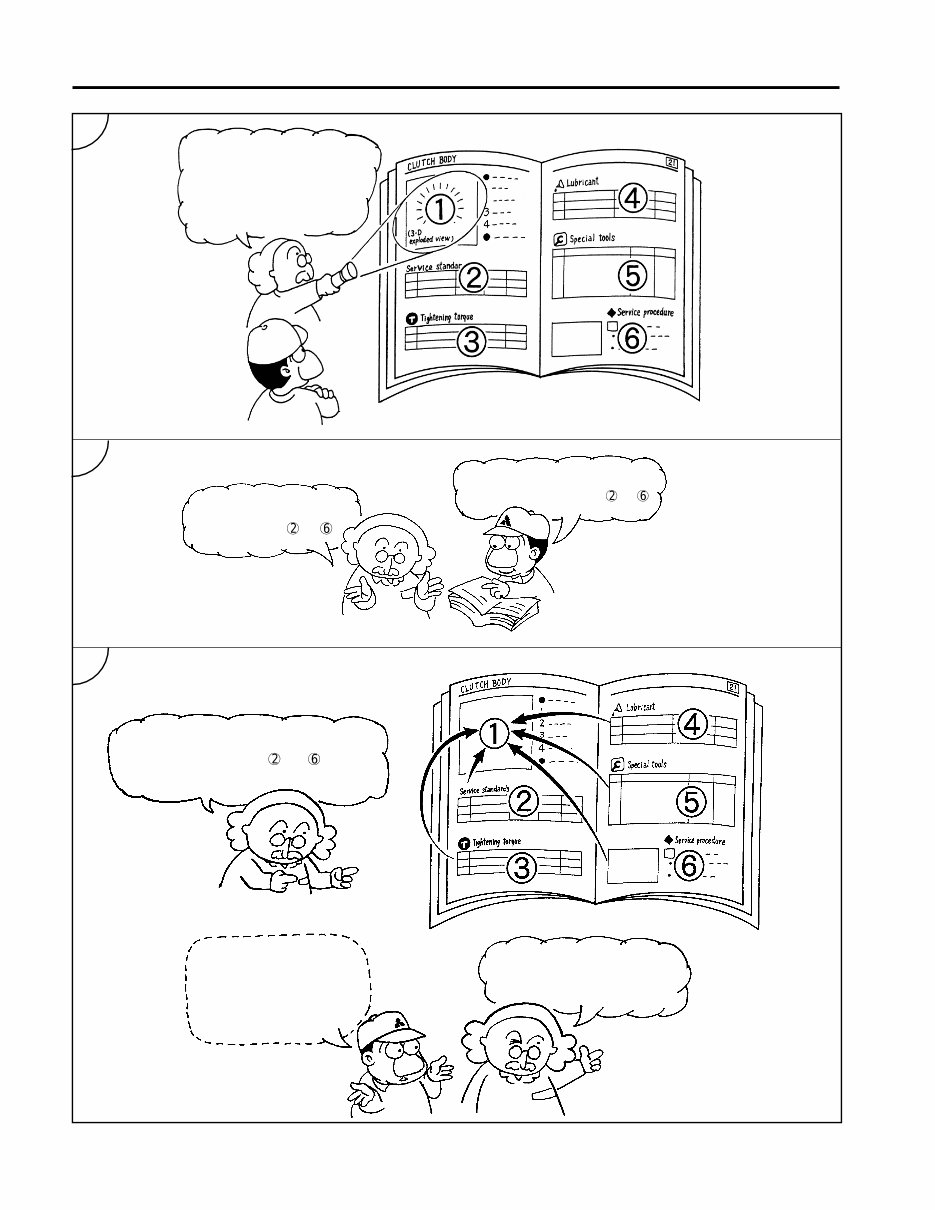
The service instructions consist of the parts shown
below. Starting on page 7, these parts are described in
detail in order of the circled numbers.
Name of system or
assembly
Key numbers
List of part
names
Group number
This appears on each
right-hand page.
Exploded view
This shows the system
or assembly in its dis-
assembled form.
Service
standards
Tightening
torques
Lubricants, fluids
and/or sealants
This table shows the required
brands and quantities of oils,
greases and/or sealants.
Special tools
Service
procedure
Service procedures
1
2
HOW THIS MANUAL IS STRUCTURED
4
23922
26312
20245
23921
26311
Look at the exploded view
first; it gives an overview of
the system or assembly.
All other information is
given in parts to .
I see... First I look at the exploded
view, then I look at parts to .
Basically, you should find the information
you need from parts to as you
perform the service procedure.
But how should I
find the information
I need?
I'll show you on the
next page.
HOW THIS MANUAL IS STRUCTURED
3
4
5
5
5.9 {4.3, 0.6}
26314
20252
45204
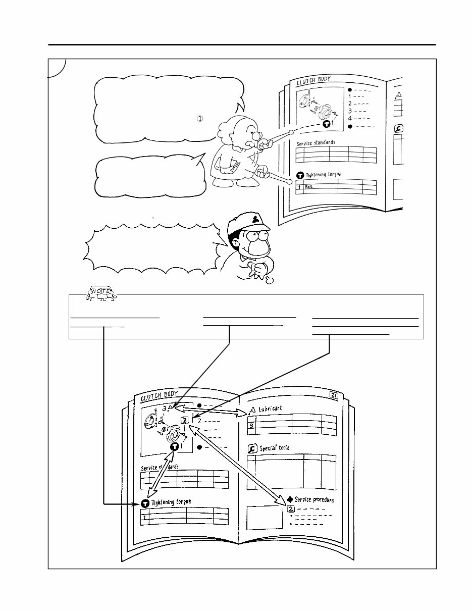
Find the information you need using
the key numbers.
For example, let's assume you're
assembling the clutch and need the
tightening torque for the bolt .
To find the tightening torque,
just look up key number 1 in the
“Tightening torques” table.
I see... The key numbers for the
exploded view match the key
numbers on other parts of the page.
To help you find information quickly:
Tightening torques are
marked with Ê .
Lubricants, fluids and seal-
ants are marked with - .
And every key number that ap-
pears in the service procedure is
enclosed with a square.
6
HOW THIS MANUAL IS STRUCTURED
6
1
1
Ê
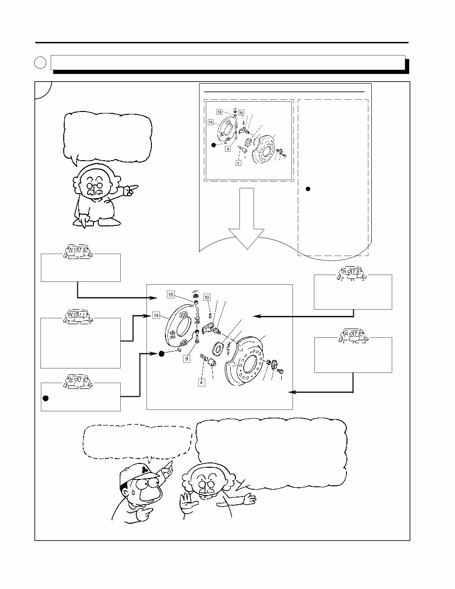
Explanatory notes for the
exploded view are given
below. Explanatory notes
for the parts list are given
on the facing page.
CLUTCH-PROPER <C5>
Pressure Plate-and-Lever Assembly
● Pre-disassembly operations
Õ P21 - 44
• Disassembly sequence
1 Bolt
2 Lock plate
3 Support nut
4 Pressure spring
5 Pressure spring cap
6 Return spring
7 Release lever plate
8 Clutch cover
9 Release lever pin
10 Support lever pin
11 Support lever
12 Release lever
13 Bushing
14 Pressure plate
P Positioning pin
Ù : Non-reusable part
NOTE
Do not remove the bushing 13
unless it is defective.
● Assembly sequence
Reverse the order of disassembly.
Repair kit : Clutch release
Lever kit
● Post-assembly Inspection
and adjustment
Õ P21 - 44
This mark indicates a part
that cannot be reused.
Pressure Plate-and-Lever Assembly
This mark indicates that
lubricant or sealant must
be applied to the part.
The key number enclosed
with a square indicates
that the part is men-
tioned in the service
procedure.
This mark indicates
that a tightening torque
is specified for the part.
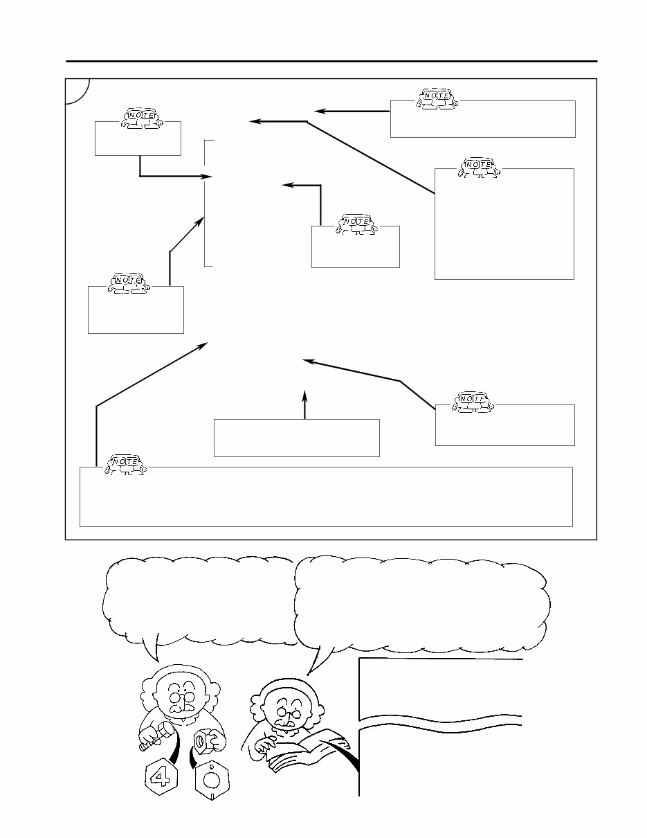
So parts without Ê marks don't
have specified tightening torques ?
No, they don't. But every bolt and nut must be
tightened to a standard torque. A Ê mark shows
either that the part must be tightened to a torque
other than the standard torque or that the standard
torque cannot be determined from the part's shape
or markings.
Standard tightening torques are explained
at the bottom of the next page.
2
3
-
-
12
7 -
8
6
11
5
-
Ù
HOW THIS MANUAL IS STRUCTURED
Exploded view
1
Ê
2 3
-
-
12
7 -
8
6
11
5
-
Ù
23925
23927
23928
1
8
23926
: Indicates positioning
pin.
P
P
P
7
PRECAUTIONS FOR MAINTENANCE
OPERATIONS .......................................
TABLE OF STANDARD
TIGHTENING TORQUES ......................
● Pre-disassembly operations
Õ P21 - 44
● Disassembly sequence
1 Bolt
2 Lock plate
3 Support nut
4 Pressure spring
5 Pressure spring cap
6 Return spring
7 Release lever plate
8 Clutch cover
9 Release lever pin
10 Support lever pin
11 Support lever
12 Release lever
13 Bushing
14 Pressure plate
Ù : Non-reusable part
NOTE
Do not remove bushing 13
unless it is faulty.
● Assembly sequence
Follow the disassembly
sequence in reverse.
Repair kit : Clutch Release
Lever kit
● Post-assembly inspection and
adjustment
Õ P21 - 44
The key numbers
are given here.
This shows that certain operations must
be performed before disassembly.
The key numbers
show the disas-
sembly sequence.
Links to reference information
are given as follows:
• Õ P21 - 44
Refer to the indicated page
of the same group.
• ^ Gr 42
Refer to the indicated group
in another manual.
The name of the specified repair
kit (if any) is given here.
The assembly sequence is given here. Assembly is usually performed in the opposite order to disassembly. If the
assembly sequence is otherwise specified, it is given in terms of key numbers like this:
● Assembly sequence
14→12→10→13→11.....
Now let's look at standard tightening
torques. Normally, bolts and nuts have
numbers or markings to show their
material strength.
Tightening torques for bolts and nuts with such
numbers and markings are shown in the Table of
Standard Tightening Torques that appears in group
00.
INDEX
ENGINE NUMBER AND NUMBER
PLATE ...................................................
+
+
+
The names of parts
are given here.
2
23930
This shows that certain operations
must be performed after assembly.
HOW THIS MANUAL IS STRUCTURED
You're Reading a Preview
What's Included?
Fast Download Speeds
Online & Offline Access
Access PDF Contents & Bookmarks
Full Search Facility
Print one or all pages of your manual
$33.99
Viewed 33 Times Today


Secure transaction
What's Included?
Fast Download Speeds
Online & Offline Access
Access PDF Contents & Bookmarks
Full Search Facility
Print one or all pages of your manual
$33.99
2002-2004 Mitsubishi Fuso Truck FE FG FH FK FM Series Service Repair Factory Manual is an electronic manual that provides comprehensive maintenance and repair information for the specified truck models. This manual is designed to be user-friendly and is suitable for both professional mechanics and DIY enthusiasts.
This manual covers the following models:
- 2002 Mitsubishi Fuso Truck FE639
- 2002 Mitsubishi Fuso Truck FE649
- 2002 Mitsubishi Fuso Truck FG639
- 2002 Mitsubishi Fuso Truck FE640
- 2002 Mitsubishi Fuso Truck FE640 W
- 2002 Mitsubishi Fuso Truck FG649
- 2003 Mitsubishi Fuso Truck FH210
- 2003 Mitsubishi Fuso Truck FH211
- 2002 Mitsubishi Fuso Truck FK617
- 2002 Mitsubishi Fuso Truck FM617
- 2002 Mitsubishi Fuso Truck FM657
The Service Repair Factory Manual includes detailed information on various aspects of the vehicles, such as:
- Forward
- How to read This Manual
- General
- Maintenance Schedule
- Engine
- Lubrication
- Fuel and Engine Control
- Cooling
- Intake and Exhaust
- Clutch
- Manual Transmission
- Automatic Transmission
- Propeller Shaft
- Front Axle
- Rear Axle
- Wheel and Tire
- Front Suspension
- Brake
- Anti-Lock Brake System (ABS)
- Parking Brake
- Steering
- Frame
- Cab
- Electrical
- Air Conditioner
- Heater
The manual is written in a step-by-step format, providing detailed instructions for easy repairs, potentially saving on expenses. The file format is compatible with all versions of Windows and Mac, and it is available in English. It requires Adobe Reader and Win for access.


