5 Body & Equipment Mounting Guide Kenworth Trucks Last revised: February 2009 Figure 47. 4-Point Body Mount.......................................................................................... 69 Figure 48. Front, 3-Point Mount ........................................................................................ 70 Figure 49. Rigid Rear Mount ............................................................................................. 70 Figure 50. Tilt Tray ............................................................................................................ 71 Figure 51. Beaver Tail Tray ............................................................................................... 72 Figure 52. Agitator Front Mount ........................................................................................ 73 Figure 53. Correct frame bolt Installation ........................................................................... 75 Figure 54. Bolt Hole Location Scribe Marks ...................................................................... 75 Figure 55. Scribe Mark Damage to Frame ........................................................................ 75 Figure 56. Kenworth Standard Chassis Hole Drill Pattern ................................................ 76 Figure 57. Location of Applied Load through Sub-Frame ................................................. 79 Figure 58. Forward Sub-Frame End Taper ....................................................................... 81 Figure 59. Sub-Frame ....................................................................................................... 82 Figure 60. Sub-Frame with Cross-Braces ......................................................................... 82 Figure 61. Change of Sub-Frame Section ........................................................................ 83 Figure 62. Typical Fifth Wheel Mounting........................................................................... 85 Figure 63. Double OScillating Fifth Wheel ........................................................................ 85 Figure 64. D-Rating, Single Trailer Prime Mover .............................................................. 86 Figure 65. D-Rating, B-Double Prime Mover .................................................................... 87 Figure 66. Typical Fifth Wheel Angle Mounting ................................................................ 88 Figure 67. D-Rating, Rigid Truck and Single Trailer ......................................................... 89 Figure 68. Wheel Clearance.............................................................................................. 91 Figure 69. PTO Isolating Mounts....................................................................................... 94 Figure 70. Driveline Components ...................................................................................... 96 Figure 71. Centre of Gravity Requirement for Vehicle .................................................... 104 Figure 72. Centre of Gravity Location (point load) .......................................................... 105 Figure 73. Centre of Gravity Locations (multiple loads) .................................................. 105 Note: The information contained in this guide is subject to change without prior notification.
6 Body & Equipment Mounting Guide Kenworth Trucks Last revised: February 2009
7 Body & Equipment Mounting Guide Kenworth Trucks Last revised: February 2009 OVERVIEW This section is an expansion of the Body & Equipment Mounting Guide that is issued to all salespersons as part of the Data Book. The guide has been produced to assist body builders mount bodywork and equipment to Kenworth truck chassis. The functional requirements apply to all truck chassis, however some of the unique design features of Kenworth Trucks will require differences in specific design areas. The Guide is not a Maintenance Manual, nor an Operation Manual, nor a Modification Authorisation. It is important to note that the requirements of the ADR's and Kenworth Trucks’ modification guidelines take precedence over any Code of Practice. Any modifications must comply with Kenworth Trucks recommendations and that the ADR compliance of the vehicle as originally manufactured by Kenworth Trucks, or a Secondary Manufacturer, is not invalidated. Vehicle Standards Bulletin No.6, (Part A, Section A, 4.4) stipulates that the "requirements of the ADR’s and original manufacture's modification guidelines shall take precedence". This manual is intended to detail those aspects of the vehicle design where Kenworth requirements differ. Under no circumstances is a vehicle to be rated higher than its original rating without written approval from Kenworth trucks. To acquire written approval the particular vehicle must be taken to an approved Kenworth dealership for verification of the modifications. Under some circumstances the original vehicle rating may be reassessed, in which case an original ratings letter can be issued stipulating the trucks new rating. In this case a Kenworth dealer is not required to examine the vehicle. SAFETY The safety of vehicle operators and mechanics must always be considered before working on/with a commercial vehicle. Any potential risks of specific processes should be considered and all addressed as part of the normal Occupational Health and Safety regime.
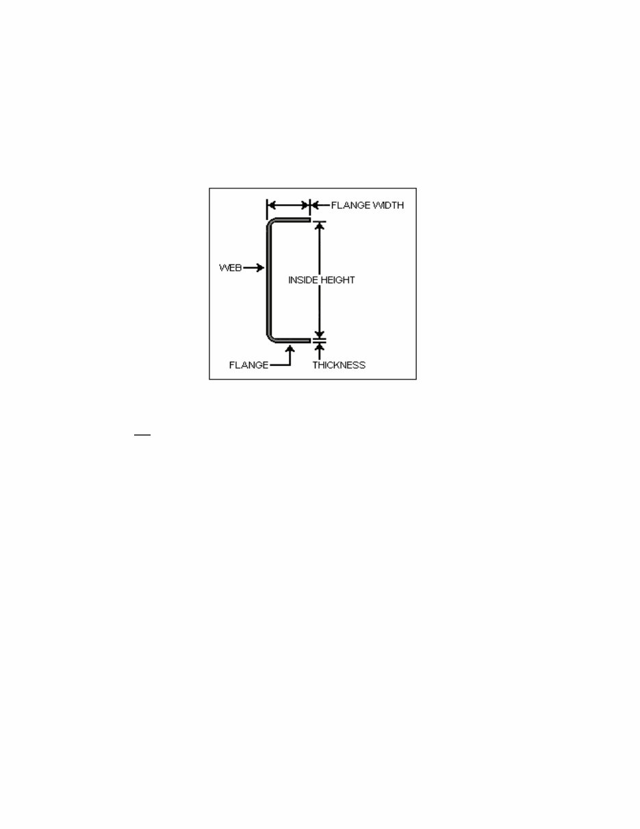
8 Body & Equipment Mounting Guide Kenworth Trucks Last revised: February 2009 GENERAL The Kenworth truck chassis design follows the usual practise for heavy commercial vehicle chassis frames to be a 'ladder` formed from channel section steel, with two main longitudinal rails extending the full length of the vehicle, and bracing crossmembers. These main rails consist of a vertical web, or side member, with top and bottom flanges Figure 1. Figure 1. Frame Section. The flanges support the downward weight of the body; for this reason drilling through the flanges is not approved. The web supports the flanges and increases the lateral and torsional stiffness of the member. Chassis frames are designed to allow a certain amount of flexibility, and thus body structures must be designed and built accordingly. Localised resistance to flexing of the chassis frame can be achieved by adding inserts or outserts (flitch plates) which have the effect of strengthening and stiffening the frame. This reinforcement is generally required around points where maximum stresses (shear force) occur, such as the mounting points for tipper bodies. Bodywork can be designed either to flex with the chassis or to remain as a semi-rigid structure whilst allowing the frame to flex independently. Where the body is allowed to flex with the chassis, it is possible to mount the longitudinal body subframe members directly to the top of the side rails. Further, the ends of the subframe should be tapered to avoid stress concentration where a sudden change in stiffness is present. Mounting the body directly onto the top flanges of the chassis will also produce poor durability, as the flanges have no vertical strength, other than that of the material section.
9 Body & Equipment Mounting Guide Kenworth Trucks Last revised: February 2009 A much more satisfactory method of body mounting to the chassis frame is by using brackets attached to the web of the frame, thus placing the downward thrust of the body weight through them. If the body is raised significantly above the chassis rails then, as well as fitting packers, fore and aft bracing must be added to prevent the sub-frame from lozenging under braking or acceleration. The method of mounting bodies described previously is only suited to situations where a degree of flexibility in both chassis and body is acceptable. There are a number of body designs where body rigidity is of prime importance, tanker bodies being an obvious case. Tank bodies should not leak, and thus must be designed as an integral structure unaffected by any flexibilities in the chassis. It is common practise, in budding tanker bodies; to utilise resilient mounting brackets combined with a transversely mounted trunnion assembly to support the front of the tank. The trunnion bracket will itself be mounted to the chassis through resilient mountings. There will usually be two or four side mountings, depending on tank length, in addition to the trunnion mounting, and these can be attached to the chassis at suitable positions relative to the tank design. Frequently, however, it will be necessary to design special chassis mounting brackets, and these should be of adequate proportions to allow a top flange to locate on the top flange of the chassis and extend vertically down the web of the chassis rail far enough to permit two parallel rows of attaching fasteners. Tipping bodies present a slightly different problem, in that a torsionally rigid body structure must be mounted in such a way as to cater for the stresses imposed during tipping, as well as the normal distribution of load into the chassis rails whilst the body is lowered. To minimise any bending moment being transmitted to the chassis rails, the rear pivot mount brackets should be located as near to, or incorporated in, the rearmost suspension brackets. Forward support brackets are required around the hoist location, plus support brackets forwards of the suspension to prevent the body sagging. In addition, lateral location will be required to ensure that the body locates squarely on the chassis frame when lowered.
10 Body & Equipment Mounting Guide Kenworth Trucks Last revised: February 2009 FRAME DON’TS Before attempting any work involving the frame rails, read the following list of items NOT to do: 1. Do not attach any parts to frame rails by welding. 2. Do not drill holes on web close to flanges. Minimum distance from hole centre is 60mm from outer edge of flange. 3. Do not drill holes in flanges of frame rails. Figure 2. DO NOT DRILL FLANGES 4. Do not drill closely spaced holes in the web of the frame, hole centres of two adjacent holes should be spaced at least three times the distance apart of the largest diameter hole. Closer spacing than this could induce a failure between the holes. 5. Do not use chains or cables wrapped around the frame rails for hoisting or straightening unless protective material is used next to the frame rails, see LIFTING below. 6. Do not leave scribe marks on frame rails. Scribe marks removed by drilling are acceptable. 7. Do not use bolts or screws that have their threaded portion against the side of the hole in the frame. 8. Do not plug weld unused bolt holes. The heat effects of welding generally reduce rail strength by more than the drill hole would. NOTE: If in doubt about any frame repair procedure, contact Kenworth Trucks, Customer Service instructions. Kenworth Trucks does not approve straightening of damaged frame rails . Damaged or distorted frame rails must be replaced.
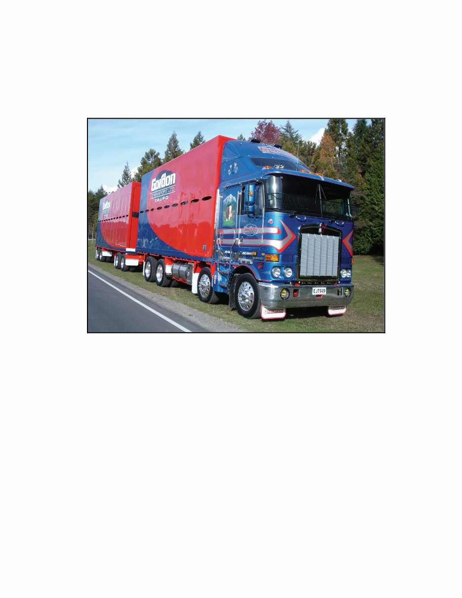
Discover the ultimate resource for mounting bodywork and equipment onto Kenworth truck chassis with the Kenworth Trucks Body & Equipment Mounting Guide. This comprehensive manual provides essential safety protocols, precise chassis dimensions, and detailed instructions on various body mounting methods, frame fasteners, and body angles. Whether you're a professional mechanic or a DIY enthusiast, this guide equips you with the technical know-how to optimize Kenworth truck performance and functionality.
Explore specialized equipment installations such as cranes, tanks, and tilt trays with confidence. The guide covers crucial topics including vehicle modifications, weight distribution checks, and legal requirements. With a detailed table of contents, this guide ensures a smooth and secure installation process, allowing you to achieve top-notch body mounting results with utmost precision and adherence to safety standards.
Table of Contents:
SAFETY
GENERAL
FRAME DON’TS
SAFETY FIRST
BASIC CHASSIS DIMENSIONS
CHASSIS FRAME
GENERAL COMMENTS
VEHICLE IDENTIFICATION
LEGAL REQUIREMENTS
AUSTRALIAN DESIGN RULES (Third Edition)
INSTALLATION OF CHASSIS MOUNTED EQUIPMENT
General Points
Critical Clearances
Chassis Side Members
Frame Drilling
Frame Welding
Body Mounting Methods
Weight Distribution
Lateral stability (dynamic)
Long Term Storage of Chassis
Body Structures
Semi-trailer Coupling
MOUNTING SYSTEMS
Type 'A' - Flat Plate
Type 'C' - Vertically Flexible
BODY ANGLES
CUSHIONING MATERIAL
MOUNTING BRACKET LAYOUT
FLATBED PLATFORM / DROPSIDE
TIPPER
TAUTLINER
SPECIALIST BODY EQUIPMENT
RIGID TIPPER
CRANES
TANKS
TILT TRAYS
BEAVER TAIL TRAY
CONCRETE AGITATOR
CRANE TRUCKS
LAYOUT OF BOLTS
FRAME FASTENERS
BODY/STRUCTURE WITH SUB-FRAME
SUB-FRAMES
FIFTH WHEEL MOUNTING
DRAWBAR CROSS MEMBER
TYRE CLEARANCE
POWER TAKE-OFFS
WHEELBASE ALTERATIONS
FRAME RAIL CUTOUTS
VEHICLE MODIFICATIONS
Engine Replacement
Transmission Replacement
Steer Axle Replacement
Rear Drive Axle(s) Replacement
Wheel/Rim Replacement
Inlet and Exhaust Modifications
Tyre Replacement
Suspension Replacement
Seat Replacement
KENWORTH WEIGHT DISTRIBUTION CHECKS
Printable: Yes Language: English Compatibility: Pretty much any electronic device, incl. PC & Mac computers, Android and Apple smartphones & tablet, etc. Requirements: Adobe Reader (free)