

IVECO STRALIS AT & AD Truck LORRY Repair Manual MECHANICAL Electric ELECTRONIC Workshop Service Shop PART
What's Included?
Fast Download Speeds
Online & Offline Access
Access PDF Contents & Bookmarks
Full Search Facility
Print one or all pages of your manual

S TRALIS AT/AD
REPAIR MANUAL
MECHANICAL
ELECTRIC
ELECTRONIC

S TRALIS AT/AD
REPAIR MANUAL

This publication describes the characteristics, the data, the
correct methodology of the repairs that can be made on each
individual component of the vehicle.
By complying with the instructions supplied and using the
specific tools it is possible to perform any repair intervention
correctly, within the specified time frames, while protecting the
technicians against incidents.
Before starting any repair work, make sure that all accident
prevention devices are ready at hand.
Check and wear the protective personal equipment provided
for by the safety standards: goggles, helmet, gloves, shoes.
Check the efficiency of all processing, lifting and transport tools
before using them.
The data contained in this publication might fail to reflect the
latest changes which the Manufacturer may introduce at any
time, for technical or sales purposes, or to meet the
requirements of local legislation.
Copy, even partial, of text and drawings is forbidden.
Publication Edited by:
IVECO S.p.A.
T.C.O. - B.U. Customer Service
Lungo Stura Lazio, 15/19
10156 Torino (Italy)
Printed 603.93.141 -1
st
Ed. 2003
B.U. TECHNICAL PUBLISHING
C.so Svizzera, 185
10149 Torino (Italy)
Produced by:
The workshop manuals for mechanical parts have been divided into Sections, each of which has a number and its relevant contents
are indicated in the General Specifications. Each section features a main Unit (e.g. engine, gears etc.).
The subjects usually dealt with in each section are:
Technical data table, Driving torques, Equipment, Diagnostic, Removal and Fitting in place, Repair operations.
Where possible, the same sequence of procedures has been followed for easy reference.
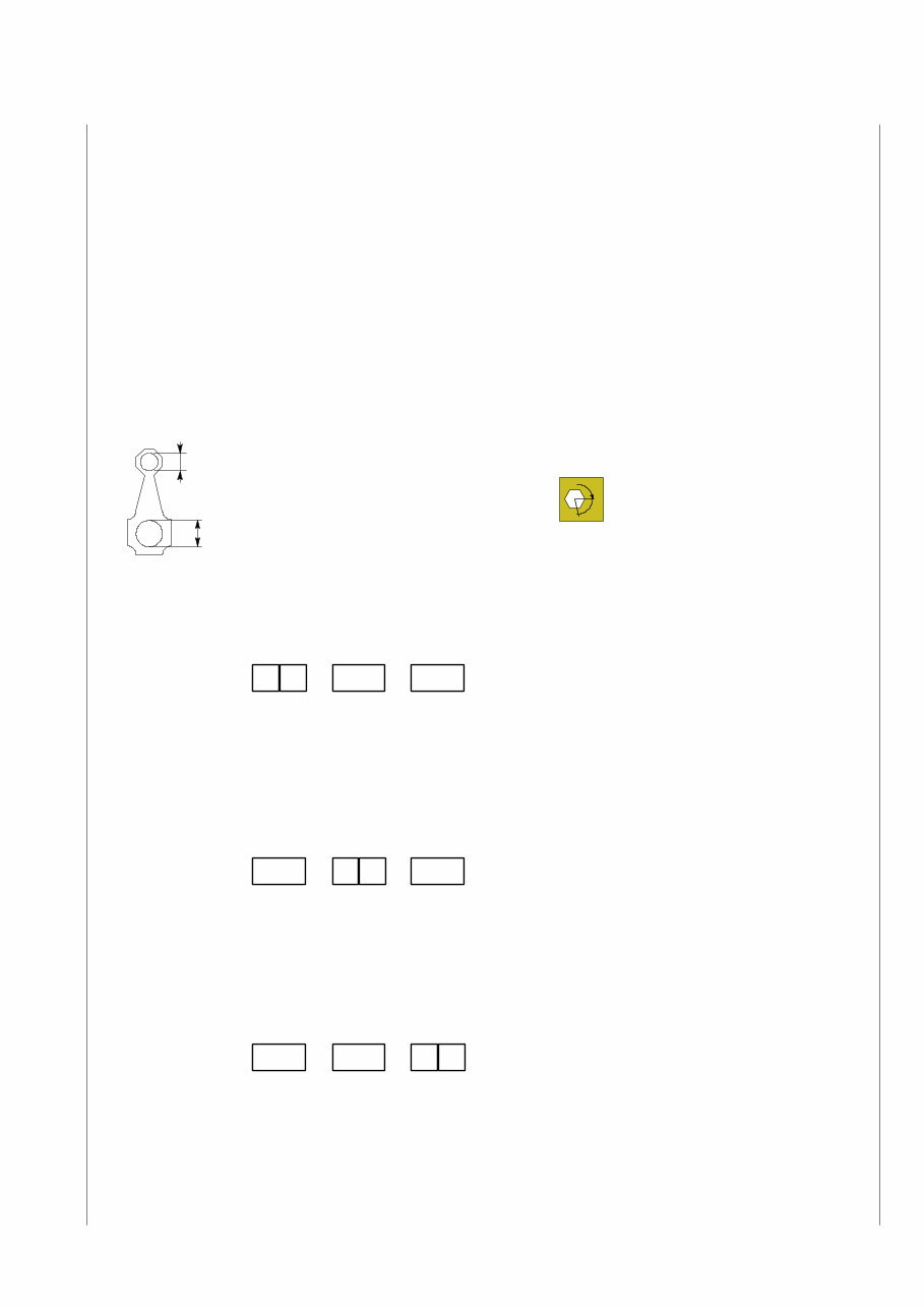
Diagrams and symbols have been widely used to give a clearer and more immediate illustration of the subject being dealt with, (see
next page) instead of giving descriptions of some operations or procedures.
Example
Ø 1 = housing for connecting rod small end bush
Ø 2 = housing for connecting rod bearings
Furthermore, within each section, every heading or sub-heading concerning the operations to be carried out is preceded by a six
digit number. This number is the Product Code that is to be found in the repair operation described in the REPAIR TIMES CHARTS
and in the FAULT CODES.
For quick reference the indication of how to read this code is described below (see the Repair time charts also).
Product Code:
Example:
Product 50 = Frame;
Product 52 = Axles;
Product 53 = Gears etc.
Unit Code:
Figures three and four identify the ASSEMBLY within the PRODUCT
Example:
Product 50 = Frame;
Unit 01 = Chassis;
Unit 02 = Bumpers etc .
Sub-assembly Code:
Example:
Product 50 = Frame;
Unit 01 = Chassis;
Sub-assembly 40 = Chassis cross members etc.
α
Tighten to torque
Tighten to torque +
angular value
1 ∅
∅ 2
5 0
PRODUCT UNIT SUB-ASSEMBLY
COMPONENT
0 1
PRODUCT UNIT SUB-ASSEMBLY
COMPONENT
4 0
PRODUCT UNIT SUB-ASSEMBLY
COMPONENT
Print 603.93.141 Base - January 2003
SPECIAL REMARKS
Base - January 2003 Print 603.93.141
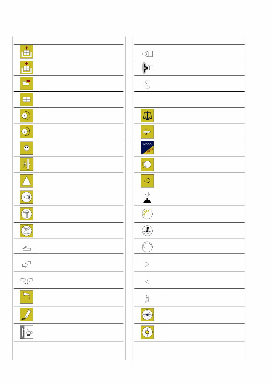
Graphs and symbols
Removal
Disconnection
Intake
Refitting
Connection
Exhaust
Removal
Disassembly
Operation
Fitting in place
Assembly
ρ
Compression ratio
Tighten to torque
Tolerance
Weight difference
α
Tighten to torque + angle value Rolling torque
Press or caulk
Replacement
Original spare parts
Regulation
Adjustment
Rotation
!
Warning
Note
Angle
Angular value
Visual inspection
Fitting position check
Preload
Measurement
Value to find
Check
Number of revolutions
Equipment Temperature
Surface for machining
Machine finish bar
Pressure
Interference
Strained assembly
Oversized
Higher than….
Maximum, peak
Thickness
Clearance
Undersized
Less than….
Minimum
Lubrication
Damp
Grease
Selection
Classes
Oversizing
Sealant
Adhesive
Temperature < 0°
Cold
Winter
Air bleeding
Temperature > 0°
Hot
Summer

Print 603.93.141 Base - January 2003
Print 603.43.671/A
STRALIS AT/AD
Print 603.93.141 — 1
st
edition
Base — January 2003
UPDATE DATA
Section Description Page Revision date

Base - January 2003 Print 603.93.141

Print 603.93.141 Base - January 2003
Section
General information 1
Engine 2
Clutch 3
Gearbox 4
Hydraulic retarder 5
Propeller shafts 6
Rear axles 7
Front axle 8
Front and rear suspensions 9
Wheels and tyres 10
Steering system 11
Pneumatic system - brakes 12
Bodywork and chassis frame 13
Maintenance 14
INDEX OF SECTIONS

Base - January 2003 Print 603.93.141

1 STRALIS AT/AD GENERAL
Print 603.93.141 Base - January 2003
SECTION 1
General
Page
VEHICLE IDENTIFICATION DATA 3 ..........
- Vehicle identification plate 4 ................
- Production identification plate 4 .............
COMPOSITION OF MODELS 5 ..............
P.I.C. NUMBER CODING 9 ..................
REPLENISHING FLUIDS 13 ...................
You're Reading a Preview
What's Included?
Fast Download Speeds
Online & Offline Access
Access PDF Contents & Bookmarks
Full Search Facility
Print one or all pages of your manual
$33.99
Viewed 39 Times Today


Secure transaction
What's Included?
Fast Download Speeds
Online & Offline Access
Access PDF Contents & Bookmarks
Full Search Facility
Print one or all pages of your manual
$33.99
►► FULL MANUAL SEE SIZE ◄◄
FULLY BOOKMARKED SO YOU CAN QUICKLY GET TO THE SECTION YOU NEED.
ALL YOU NEED TO KNOW MANUAL....
IVECO STRALIS AT & AD
REPAIR MANUAL
MECHANICAL
ELECTRIC
ELECTRONIC
SECTIONS:
- General information
- Engine
- Clutch
- Gearbox
- Hydraulic retarder
- Propeller shafts
- Rear axles
- Front axle
- Front and rear suspensions
- Wheels and tyres
- Steering system
- Pneumatic system - brakes
- Bodywork and chassis frame
- Maintenance
STRALIS AT AD
REPAIR MANUAL
MECHANICAL
ELECTRIC
ELECTRONIC


