

2002-2008 Iveco EuroCargo Tector (6-26T) Truck Service & Repair Manual
What's Included?
Fast Download Speeds
Offline Viewing
Access Contents & Bookmarks
Full Search Facility
Print one or all pages of your manual

EURO CARGO TECTOR
6 TO 10 t
REPAIR MANUAL

Manuals for repairs are split into Sections, each one of which is marked by a numeral; the contents of these sections are indicated
in the general table of contents.
Each section is generally dedicated to a main Unit (e.g.: engine, gearbox, electric system, etc.).
Sections with mechanical contents include technical data, tightening torque collections, tool lists, connections — disconnections of
units to/from the vehicle, overhauls at the bench and relating troubleshooting.
On the electric/electronic system section there are the descriptions of the electric network and vehicle electronic systems, electric
schemes, components electric characteristics, components codes and troubleshooting relating to the central units specific of the
electric system.
The manual uses proper symbols in its descriptions; the purpose of these symbols is to classify contained information. In particular,
there have been defined a set of symbols to classify warnings and a set for assistance operations.
PRELIMINARY REMARKS
General danger
It includes the dangers of above described signals.
Danger of serious damage for the vehicle
Partial or complete non observance of these prescriptions can cause serious damages to the vehicle and sometimes
guarantee lapse too.
Environment protection
It indicates correct behaviour in order that vehicle use is environmentally friendly as much as possible.
Danger for persons
Missing or incomplete observance of these prescriptions can cause serious danger for persons’ safety.
SYMBOLS — WARNINGS
It indicates an additional explanation for a piece of information.
!
NOTE
Print 603.93.381 Base — October 2004
I
Base — October 2004 Print 603.93.381
II
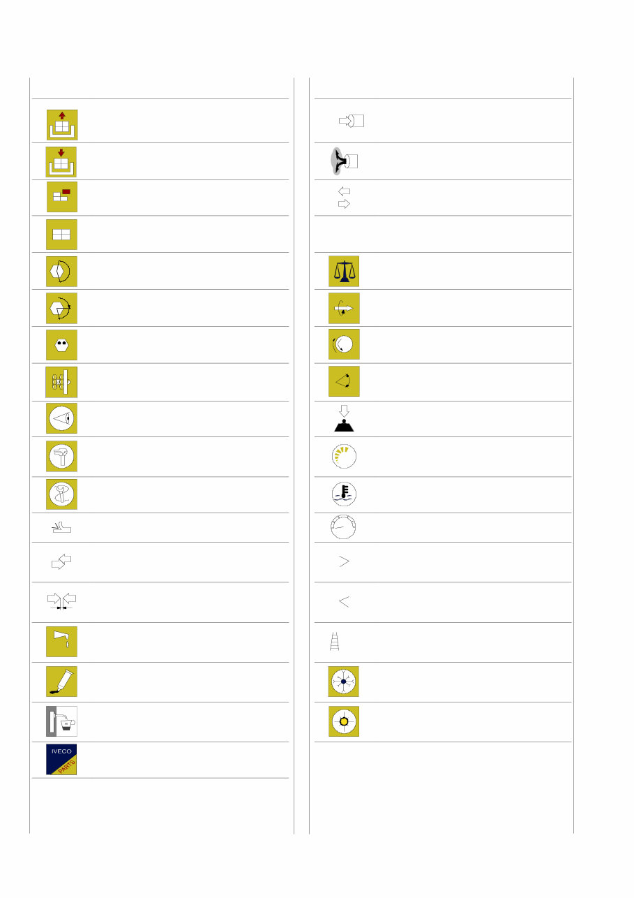
SYMBOLS — ASSISTANCE OPERATIONS
Removal
Disconnection
Intake
Refitting
Connection
Exhaust
Removal
Disassembly
Operation
Fitting in place
Assembly
ρ Compression ratio
Tighten to torque
Tolerance
Weight difference
α
Tighten to torque + angle value Rolling torque
Press or caulk Rotation
Regulation
Adjustment
Angle
Angular value
Visual inspection
Fitting position check
Preload
Measurement
Value to find
Check
Number of revolutions
Equipment Temperature
Surface for machining
Machine finish
bar
Pressure
Interference
Strained assembly
Oversized
Higher than….
Maximum, peak
Thickness
Clearance
Undersized
Less than….
Minimum
Lubrication
Damp
Grease
Selection
Classes
Oversizing
Sealant
Adhesive
Temperature < 0 °C
Cold
Winter
Air bleeding
Temperature > 0 °C
Hot
Summer
Replacement
Original spare parts

Each title or subtitle concerning operations being performed is preceded by a six—figure number named PRODUCT CODE.
This number represents the PRODUCT CODE referred to by the repair operation contained in both REPAIR TIMES and
TROUBLE CODE document.
As a quick reference there are shown below the guide lines to read this code (see Repair Timing, too).
Product Code:
The first and second figures identify the PRODUCT within motor vehicle.
Example :
Product 50 = Vehicle chassis;
Product 52 = Axles;
Product 53 = Transmission;
Product 76 = Electric ssystem.
Unit Code:
The third and fourth figures identify the UNIT within the PRODUCT.
Example :
Product 50 = Vehicle chassis;
Unit 01 = Chassis;
Unit 02 = Bumpers;
Unit 03 = Alternator.
Sub—assembly Code:
The fifth and sixth figures exactly identify the SUB—ASSEMBLY and Component of a Unit within a PRODUCT.
Example :
Product 50 = Vehicle chassis;
Unit 01 = Chassis;
Sub—assembly 40 = Chassis cross members;
Sub—assembly 13 = Rotor.
PRODUCT CODE
5 0
PRODUCT UNIT SUB—ASSEMBLY
COMPONENT
0 1
4 0
7 6
0 3
1 3
PRODUCT UNIT SUB—ASSEMBLY
COMPONENT
PRODUCT UNIT SUB—ASSEMBLY
COMPONENT
PRODUCT UNIT SUB—ASSEMBLY
COMPONENT
PRODUCT UNIT SUB—ASSEMBLY
COMPONENT
PRODUCT UNIT SUB—ASSEMBLY
COMPONENT
Print 603.93.381 Base — October 2004
III

GENERAL WARNINGS
Warnings shown cannot be representative of all danger situations possibly occurring. Therefore, it is suggested to contact
immediate superiors where a danger situation occurs which is not described.
Use both specific and general—purpose toolings according to the prescriptions contained in respective use and
maintenance handbooks. Check use state and suitability of tools not subjected to regular check.
The manual handling of loads must be assessed in advance because it also depends, besides weight, on its size and on
the path.
Handling by mechanical means must be with hoisters proper as for weight as well as for shape and volume. Hoisters,
ropes and hooks used must contain clear indications on maximum carrying capacity acceptable. The use of said means
is compulsorily permitted to authorised personnel only. Stay duly clear of the load, and, anyhow, never under it.
In disassembling operations, always observe provided prescriptions; prevent mechanical parts being taken out from
accidentally striking workshop personnel.
Workshop jobs performed in pairs must always be performed in maximum safety; avoid operations which could be
dangerous for the co—operator because of lack of visibility or of his/her not correct position.
Keep personnel not authorised to operations clear of working area.
Learn operation and safety knowledge necessary relating to the vehicle prior to each intervention on it. Scrupulously
observe all safety warnings on the vehicle. Apply suitable signals for the vehicles being repaired. Once the repair
intervention has been completed, before starting up the vehicle, perform all checks indicated on paragraph “Controls
care of user” of Use and Maintenance handbook.
In lack of visibility in operating from the vehicle, charge a person on the ground with assistance. Do not leave unmanned
a vehicle in motion during repair interventions.
Keep the vehicle stationary by proper chocks.
In the case of an intervention on a vehicle lifted from the ground, check the vehicle to be quite steady on special support
stands and, in the case of lifting by means of a lift, check manual/automatic safeties to be activated.
When it is necessary to perform an intervention on methane—fed vehicles, observe the indications contained inside the
document, as well as all specific safety regulations provided.
Only remove radiator cap when the engine is cold by cautiously unscrewing it in order to let system residual pressure
out.
Inflammable fuel and all inflammable fluids and liquids must be handled with care, according to what contained on harmful
materials 12—point cards. Refuelling must be performed outdoors with the engine off, avoiding lit cigarettes, free flames
or sparks in order to prevent sudden fires/bursts. Adequately store inflammable, corrosive and polluting fluids and liquids
according to what provided by regulations in force. Compulsorily avoid to use food containers to store harmful liquids.
Avoid to drill or bore pressurised containers, and throw cloths impregnated with inflammable substances into suitable
containers.
Worn out, damaged or consumable parts must be replaced by Iveco original spares.
During workshop activity, always keep the work place clean; timely clear or clean floors from accidental liquid or oil spots.
Electric sockets and electric equipment necessary to perform repair interventions must meet safety rules.
For every intervention on vehicle hydraulic, pneumatic, conditioning and AIR — BAG systems, scrupulously observe
indications specified in relating manual sections.
!
Base — October 2004 Print 603.93.381
IV

GENERAL WARNINGS
Clean units or assemblies detached from the vehicle and carefully check their integrity before overhaul. Tidy up detached
or disassembled parts with their securing elements (screws, nuts, etc.) into special containers.
Check for the integrity of the parts which prevent screws from being unscrewed: broken washers, dowels, clips, etc.
Self—locking nuts with an insert made of nylon must always be replaced.
Avoid contact of rubber parts with diesel oil, petrol or other not compatible substances.
Before washing under pressure mechanical parts, protect electric connectors, and central units, if present.
Tightening screws and nuts must always be according to prescriptions; IVECO commercial and assistance network is
available to give all clarifications necessary to perform repair interventions not provided in this document.
Before welding:
- Disconnect all electronic central units, take power cable off battery positive terminal (connect it to chassis bonding)
and detach connectors.
- Remove paint by using proper solvents or paint removers and clean relevant surfices with soap and water.
- Await about 15 minutes before welding.
- Equip with suitable fire resistant protections to protect hoses or other components where fluids or other materials
flow which may catch fire easily on welding.
Should the vehicle be subjected to temperatures exceeding 80°C (dryer ovens), disassemble drive electronic central
units.
The disposal of all liquids and fluids must be performed with full observance of specific rules in force.
Put on, where required by the intervention, garments and protections provided in accident prevention rules; contact
with moving parts can cause serious injuries. Use suitable, preferably tight—fitted garments, and avoid to use jewels,
scarves, etc.
Do not leave the engine in motion at workshop locations not provided with a pipe to scavenge exhaust gas outside.
Avoid to breathe fumes coming from heating or from paint welding because they can cause damages to health; operate
outdoors or in suitably ventilated areas. Put on proper inspirator if paint powder is present.
Avoid contact with hot water or steam coming from the engine, radiator and pipings because they could cause serious
burns. Avoid direct contact with liquids and fluids present in vehicle systems; where an accidental contact has occurred,
refer to 12—point cards for provisions to make.
Print 603.93.381 Base — October 2004
V

GENERAL WARNINGS ON THE ELECTRIC SYSTEM
To start up the engine, do not use fast chargers. Start up must only be performed with either separate batteries or special
truck.
A wrong polarisation of supply voltage in drive electronic central units (for instance, a wrong polarisation of batteries)
can cause them to be destroyed.
Disconnect the batteries from the system during their recharging with an external apparatus.
On connecting, only screw up connector (temperature sensors, pressure sensors etc.) nuts at prescribed tightening
torque.
Before disconnecting the junction connector from an electronic central unit, isolate the system.
Do not directly supply electronic central units servo components at nominal vehicle voltage.
Cables must be arranged such as to result to be parallel to reference plane, i.e. as close as possible to chassis/body
structure.
Once the intervention on the electric system has been completed, recover connectors and wiring harnesses according
to original arrangement.
Key memorisation procedures are influenced by electromagnetic jamming (mobile phones, etc.). Therefore, during key
memorisation:
1 Pay attention that jamming sources are not present in the cab or near the keys.
2. Keys not insered in the panel must be at least 1 meter away.
If an intervention has to be made on the electric/electronic system, disconnect batteries from the system; in this case,
always disconnect, as a first one, the chassis bonding cable from batteries negative terminal.
Before connecting the batteries to the system, make sure that the system is well isolated.
Disconnect the external recharging apparatus from the public utility network before taking apparatus pins off battery
terminals.
Do not cause sparks to be generated in checking if the circuit is energised.
Do not use a test lamp in checking circuit continuity, but only use proper control apparatuses.
Make sure that the electronic devices wiring harnesses (length, lead type, location, strapping, connection to screening
braiding, bonding, etc.) comply with IVECO system and are carefully recovered after repair or maintenance
interventions.
Measurements in drive electronic central units, plugged connections and electric connections to components can only
be made on proper testing lines with special plugs and plug bushes. Never use improper means like wires, screwdrivers,
clips and the like in order to avoid the danger of causing a short circuit, as well as of damaging plugged connections, which
would later cause contact problems.
Connectors present must be seen from cable side. Connectors views contained in the manual are representative of cable
side.
!
NOTE
Base — October 2004 Print 603.93.381
VI
Print 603.93.381 Base — October 2004
VII
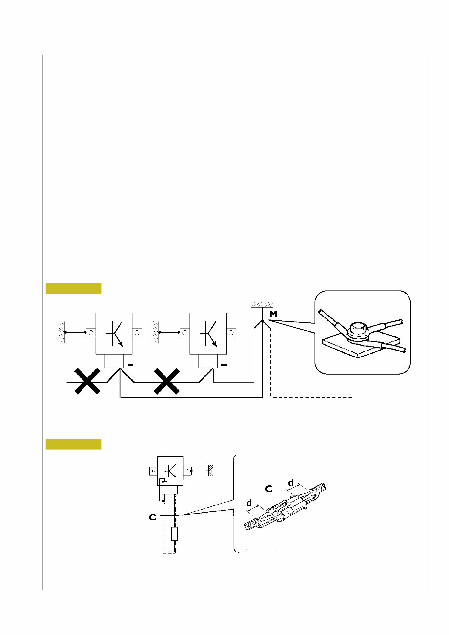
Bonding and screening
Negative leads connected to a system bonded point must be both as short and possible and “star“—connected to each other, trying
then to have their centering tidily and properly made (Figure 1, re. M).
Further, following warnings are to be compulsorily observed for electronic components:
— Electronic central units must be connected to system bonding when they are provided with a metallic shell.
— Electronic central units negative cables must be connected both to a system bonding point such as the dashboard opening
bonding (avoiding “serial“ or “chain“ connections), and to battery negative terminal.
— Analog bonding (sensors), although not connected to battery negative system/terminal bonding, must have optimal isolation.
Consequently, particularly considered must be parasitic resistances in lugs: oxidising, clinching defects, etc.
— Screened circuits braiding must only electrically contact the end towards the central unit entered by the signal (Figure 2).
— If junction connectors are present, unscreened section d, near them, must be as short as possible (Figure 2).
— Cables must be arranged such as to result to be parallel to reference plane, i.e. as close as possible to chassis/body structure.
1. NEGATIVE CABLES “STAR“ CONNECTION TO SYSTEM BONDING M
2. SCREENING THROUGH METALLIC BRAIDING OF A CABLE TO AN ELECTRONIC COMPONENT — C. CONNECTOR
d. DISTANCE ! 0
88039
Figure 1
Figure 2

Base — October 2004 Print 603.93.381
VIII
OPTIONAL ELECTRICAL AND MECHANICAL PARTS INSTALLATIONS
Accessories mounting, additions and modifications on the vehicle are to be performed complying with IVECO mounting
instructions (specific document “Instructions for transformation and preparation” is available at Assistance Network workshops).
It is reminded that, especially about the electric system, several electric sockets are provided for as series (or optional) sockets in
order to simplify and normalise the electrical intervention that is care of preparation personnel.
For any exception to mounting instructions, IVECO’s authorisation is necessary.
Lack of observance of above described prescriptions involves guarantee lapse.
It is absolutely forbidden to make modifications or connections to electric central units wiring harnesses; in particular,
the data interconnection line between central units (CAN line) is to be considered inviolable.
CONVERSIONS BETWEEN THE MAIN UNITS OF MEASUREMENT OF THE
INTERNATIONAL SYSTEM AND MOST USED DERIVED QUANTITIES
Power
1 kW = 1.36 metric HP
1 kW = 1.34 HP
1 metric HP = 0.736 kW
1 metric HP = 0.986 HP
1 HP = 0.746 kW
1 Hp = 1.014 metric HP
Torque
1 Nm = 0.1019 kgm
1 kgm = 9.81 Nm
Revolutions per time unit
1 rad/s = 1 rpm x 0.1046
1 rpm = 1 rad/s x 9.5602
Pressure
1 bar = 1.02 kg/cm
2
1 kg/cm
2
= 0.981 bar
1 bar = 10
5
Pa
(Nm and bar units are converted according to 10:1 and 1:1 for the sake of simplicity)
1 kgm = 10 Nm
1 kg/cm
2
= 1 bar
Temperature
0° C = 32° F
1° C = (1 x 1.8 + 32) ° F

Print 603.93.381 Base — October 2004
EUROCARGO TECTOR
6 TO 10 t
Print 603.93.381 — 1
st
edition
Base — October 2004
UPDATE DATA
Section Description Page Revision date
You're Reading a Preview
What's Included?
Fast Download Speeds
Offline Viewing
Access Contents & Bookmarks
Full Search Facility
Print one or all pages of your manual
$41.99
Viewed 80 Times Today


Secure transaction
What's Included?
Fast Download Speeds
Offline Viewing
Access Contents & Bookmarks
Full Search Facility
Print one or all pages of your manual
$41.99
Thank you for considering this comprehensive 2002-2008 Iveco EuroCargo Tector (6-26T) Truck Service & Repair Manual. This manual is an essential resource for professional mechanics and DIY enthusiasts, providing detailed instructions and high-quality illustrations for every repair and maintenance procedure.
Key Features:
- Covers all models, engines, trim levels, and transmission types for the Iveco EuroCargo Tector (6-26T) from 2002 to 2008
- Step-by-step repair and service procedures with detailed illustrations
- Designed to help reduce repair costs by enabling you to perform maintenance and repairs on your own
- Digital format allows you to print specific pages, chapters, or the entire manual, and it can be accessed on your tablet, smartphone, or computer
- Easy compatibility with PC, MAC, and mobile devices using Adobe Reader, available free of charge
- Instant delivery via email upon payment confirmation with Visa, MasterCard, or PayPal
This high-quality Service Repair Workshop Manual is created to meet all your truck service needs, ensuring that every aspect of the Iveco EuroCargo Tector (6-26T) is covered. Customer satisfaction is guaranteed with this indispensable manual.


