ANTI-LOCK BRAKE SYSTEM (ABS) 5A4–1 SECTION 5A4 CONTENTS ANTI-LOCK BRAKE SYSTEM (ABS) Service Precaution......................................... 5A4–2 General Description ....................................... 5A4–3 System Components .................................. 5A4–3 Electronic Hydraulic Control Unit (EHCU) .. 5A4–3 Hydraulic Unit (HU) ..................................... 5A4–3 ABS Warning Light ..................................... 5A4–4 Wheel Speed Sensor (WSS) ...................... 5A4–4 Normal and Anti-lock Braking ..................... 5A4–4 Brake Pedal Travel ..................................... 5A4–4 Acronyms and Abbreviations ...................... 5A4–4 General Diagnosis ......................................... 5A4–5 General Information .................................... 5A4–5 ABS Service Precautions ........................... 5A4–5 Computer System Service Precautions ...... 5A4–5 General Service Precautions ...................... 5A4–5 Note on Intermittents .................................. 5A4–5 Test Driving ABS Complaint Vehicles ........ 5A4–6 “ABS” Warning Light ................................... 5A4–6 Normal Operation ....................................... 5A4–6 Circuit Diagram ........................................... 5A4–7 Connector List ............................................ 5A4–8 Part Location .............................................. 5A4–10 EHCU (Electronic Hydraulic Control Unit) .. 5A4–11 EHCU Pin–outs .......................................... 5A4–12 Tech 2 Scan Tool ....................................... 5A4–14 Tech 2 Features ......................................... 5A4–15 Getting Started ........................................... 5A4–15 Operating Procedure (For Example) .......... 5A4–16 DTC Modes ................................................ 5A4–17 DTC Information Mode ............................... 5A4–17 Plotting Snapshot Graph ............................ 5A4–18 Plotting Graph Flow Chart (Plotting graph after obtaining vehicle information) ............ 5A4–19 Flow Chart for Snapshot Replay (Plotting Graph) ........................................................ 5A4–20 Tech 2 Data Display ................................... 5A4–21 Special Function ......................................... 5A4–21 Diagnostic Trouble Codes ............................. 5A4–27 Diagnosis By “ABS” Warning Light Illumination Pattern ...................................... 5A4–28 Diagnostic Trouble Codes (DTCs) .............. 5A4–28 Basic Diagnostic Flow Chart ....................... 5A4–31 Basic Inspection Procedure ........................ 5A4–32 Symptom Diagnosis ....................................... 5A4–33 ABS Works Frequently But Vehicle Does Not Decelerate ........................................... 5A4–33 Uneven Braking Occurs While ABS Works 5A4–33 The Wheels Are Locked ............................. 5A4–34 Brake Pedal Feed Is Abnormal ................... 5A4–34 Braking Sound (From EHCU) Is Heard While Not Braking ...................................... 5A4–35 No ABS Warning Light ................................ 5A4–36 Rear Wheel Speed Sensor Inspection Procedure .................................................... 5A4–37 DTC C0271 (Flash Code 14) EHCU Abnormality .................................................. 5A4–38 DTC C0277 (Flash Code 15) EHCU Power Supply Low Input or High Input .................... 5A4–39 DTC C0299 (Flash Code 25) Exhaust Brake Cut Malfunction ................................. 5A4–40 DTC C0267 (Flash Code 33) ABS Motor Abnormality .................................................. 5A4–40 DTC C0268 (Flash Code 34) Abnormal ABS motor Rotation ..................................... 5A4–41 DTC C0265 (Flash Code 41) Fail Safe Relay (FSR) {Solenoid Valve Relay} Abnormality .................................................. 5A4–41 DTC C0241 (Flash Code 43) Solenoid Control Circuit Malfunction .......................... 5A4–42 DTC C0242 (Flash Code 45) Solenoid Control Monitor Error ................................... 5A4–42 DTC C0225 (Flash Code 51) Front Left Wheel Speed Sensor Short Circuit or Circuit ......................................................... 5A4–43 DTC C0221 (Flash Code 52) Front Right Wheel Speed Sensor Short Circuit or Circuit Open ................................................ 5A4–44 DTC C0235 (Flash Code 53) Rear Left Wheel Speed Sensor Short Circuit or Circuit Open ................................................ 5A4–45 DTC C0231 (Flash Code 54) Rear Right Wheel Speed Sensor Short Circuit or Circuit Open ................................................. 5A4–46 DTC C0226 (Flash Code 61) Front Left Wheel Sensor Incorrect Signal or Tire Diameter Error ............................................. 5A4–47 DTC C0222 (Flash Code 62) Front Right Wheel Sensor Incorrect Signal or Tire Diameter Error ............................................. 5A4–48 DTC C0236 (Flash Code 63) Rear Left Wheel Sensor Incorrect Signal or Tire Diameter Error ............................................. 5A4–49 DTC C0232 (Flash Code 64) Rear Right Wheel Sensor Incorrect Signal or Tire Diameter Error ............................................. 5A4–50 Electronic Hydraulic Control Unit (EHCU) ..... 5A4–51
5A4–2 ANTI-LOCK BRAKE SYSTEM (ABS) EHCU and Associated Parts ...................... 5A4–51 Removal ..................................................... 5A4–52 Installation .................................................. 5A4–52 Front Speed Sensor....................................... 5A4–53 Front Speed Sensor and Associated Parts 5A4–53 Removal ..................................................... 5A4–53 Inspection and Repair ................................. 5A4–53 Installation .................................................. 5A4–54 Front Speed Sensor Rotor ............................. 5A4–55 Front Speed Sensor Rotor and Associated Parts ........................................................... 5A4–55 Removal ..................................................... 5A4–55 Inspection and Repair ................................. 5A4–56 Installation................................................... 5A4–56 Rear Speed Sensor ....................................... 5A4–57 Rear Speed Sensor and Associated Parts . 5A4–57 Removal...................................................... 5A4–58 Inspection and Repair ................................. 5A4–58 Installation................................................... 5A4–58 Rear Speed Sensor Rotor ............................. 5A4–59 Rear Speed Sensor Rotor and Associated Parts ........................................................... 5A4–59 Removal...................................................... 5A4–59 Inspection and Repair ................................. 5A4–59 Installation................................................... 5A4–59 Special Tools .............................................. 5A4–61 Service Precaution CAUTION: Always use the correct fastener in the proper location. When you replace a fastener, use ONLY the exact part number for that application. ISUZU will call out those fasteners that require a replacement after removal. ISUZU will also call out the fasteners that require thread lockers or thread sealant. UNLESS OTHERWISE SPECIFIED, do not use supplemental coatings (Paints, greases, or other corrosion inhibitors) on threaded fasteners or fastener joint interfaces. Generally, such coatings adversely affect the fastener torque and the joint clamping force, and may damage the fastener. When you install fasteners, use the correct tightening sequence and specifications. Following these instructions can help you avoid damage to parts and systems.
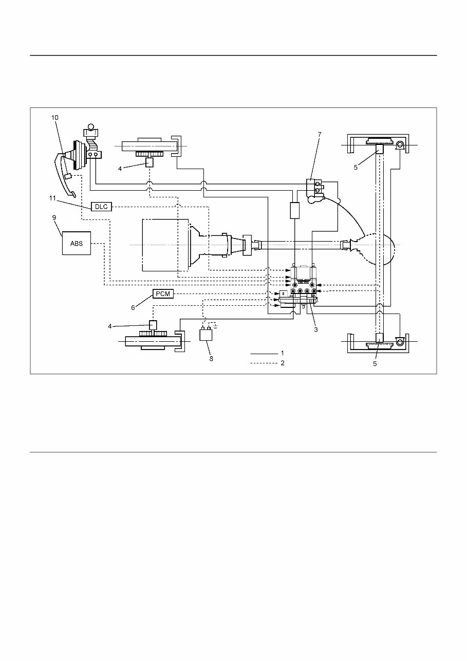
ANTI-LOCK BRAKE SYSTEM (ABS) 5A4–3 General Description The Anti-lock Brake System (ABS) works on all four wheels. A combination of wheel speed sensor and Electronic Hydraulic Control Unit (EHCU) can determine when a wheel is about to stop turning and adjust brake pressure to maintain best braking. This system helps the driver maintain greater control of the vehicle under heavy braking conditions. LNW35ALF000301 E nd O FCallo ut System Components The Anti-lock Brake System consists of a Hydraulic Unit, Electronic Hydraulic Control Unit (EHCU), four Wheel Speed Sensors and Warning Light. Electronic Hydraulic Control Unit (EHCU) The EHCU consists of ABS control circuits, fault detector, and a fail-safe. It drives the hydraulic unit according to the signal from each sensor, cancelling ABS to return to normal braking when a malfunction has occurred in the ABS. The EHCU is self-diagnosing function which can indicate faulty circuits during diagnosis. The EHCU is located behind the glove box. Hydraulic Unit (HU) The hydraulic unit is mounted on the frame near the rear spring front bracket. It consists of a Motor, Plunger Pump, Solenoid Valves and Check Valve. On the outside, the relay box containing a motor relay and a valve relay is installed. Solenoid Valves: Reduces or holds the caliper fluid pressure for each front disc brake or both rear drum brakes according to the signal sent from the EHCU. Reservoir: Temporarily holds the brake fluid that returns from the front and rear wheel brake so that pressure of front wheel brake can be reduced smoothly. Plunger Pump: Feeds the brake fluid held in the reservoir to the master cylinder. Motor: Drives the pump according to the signal from EHCU. Check Valve: Controls the brake fluid flow. Legend (1) Hydraulic Line (2) Electronic Line (3) Electronic Hydraulic Control Unit (EHCU) (4) Front Wheel Speed Sensor (5) Rear Wheel Speed Sensor (6) Powertrain Control Unit Module (PCM) (7) Load Sensing Proportioning Valve (LSPV) (8) Battery (9) ABS Warning Light (10) Brake Switch (11) Data Lint Connector
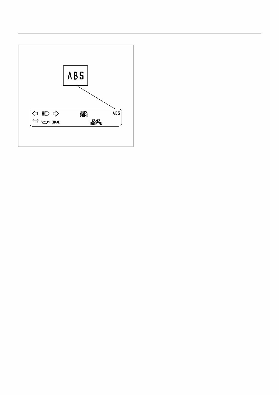
5A4–4 ANTI-LOCK BRAKE SYSTEM (ABS) ABS Warning Light LNW35ASH000101 Vehicles equipped with the Anti-lock Brake System have an amber “ABS” warning light in the instrument panel. The “ABS” warning light will illuminate if a malfunction in the Anti-lock Brake System is detected by the Electronic Hydraulic Control Unit (EHCU). In case of an electronic malfunction, the EHCU will turn “ON” the “ABS” warning light and disable the Anti-lock braking function. The “ABS” light will turn “ON" after the ignition switch is to the “ON” position. “ABS” light will normally go on and off two times and then will go out after the engine starting. If the “ABS” light comes “ON" and stays “ON” while driving, the Anti-lock Brake System should be inspected for a malfunction according to the diagnosis procedure. Wheel Speed Sensor (WSS) It consists of a sensor and a rotor. The sensor is attached to the knuckle on the front wheels and to the bracket on the brake back plate on the rear wheels. The front speed sensor is coil type and rear is Hall IC type. The sensor rotors press-fitted to front and rear wheel hubs output pulse frequency depending on wheel rotation. The speed sensors find vehicle speed from its frequency. Normal and Anti-lock Braking Under normal driving conditions, the Anti-lock Brake System functions the same as a standard power assisted brake system. However, with the detection of wheel lock-up, a slight bump or kick-back will be felt in the brake pedal. This pedal “bump” will be followed by a series of short pedal pulsations which occurs in rapid succession. The brake pedal pulsation will continue until there is no longer a need for the anti-lock function or until the vehicle is stopped. A slight ticking or popping noise may be heard during brake applications when the Anti-lock features is being used. When the Anti-lock feature is being used, the brake pedal may rise even as the brakes are being applied. This is also normal. Maintaining a constant force on the pedal will provide the shortest stopping distance. Brake Pedal Travel Vehicles equipped with the Anti-lock Brake System may be stopped by applying normal force to the brake pedal. Although there is no need to push the pedal beyond the point where it stops or holds the vehicle, by applying more force the pedal will continue to travel toward the floor. This extra brake pedal travel is normal. Acronyms and Abbreviations Several acronyms and abbreviations are commonly used throughout this section: ABS Anti-lock Brake System CKT Circuit DLC Data Link Connector DTC Diagnostic Trouble Code DVM Digital Volt Meter (High Impedance Multimeter) EHCU Electronic Hydraulic Control Unit FL Front Left FR Front Right GEN Generator HU Hydraulic Unit MV Millivolts RL Rear Left RR Rear Right RPS Revolution per Second SW Switch VDC Volts DC
ANTI-LOCK BRAKE SYSTEM (ABS) 5A4–5 VAC Volts AC W/L Warning Light WSS Wheel Speed Sensor General Diagnosis General Information ABS malfunction can be classified into two types, those which can be detected by the ABS warning light and those which can be detected as a vehicle abnormality by the driver. In either case, locate the fault in accordance with the “BASIC DIAGNOSTIC FLOWCHART” and repair. Please refer to Section 5A for the diagnosis of mechanical troubles such as brake noise, brake judder (brake pedal or vehicle vibration felt when braking), uneven braking, and parking brake trouble. ABS Service Precautions Required Tools and Items: • Box Wrench • Brake Fluid • Special Tool Some diagnosis procedures in this section require the installation of a special tool. J-39200 High Impedance Multimeter When circuit measurements are requested, use a circuit tester with high impedance. Computer System Service Precautions The Anti-lock Brake System interfaces directly with the Electronic Hydraulic Control Unit (EHCU) which is a control computer that is similar in some regards to the Engine Control Module. These modules are designed to withstand normal current draws associated with vehicle operation. However, care must be taken to avoid overloading any of the EHCU circuits. In testing for opens or shorts, do not ground or apply voltage to any of the circuits unless instructed to do so by the appropriate diagnostic procedure. These circuits should only be tested with a high impedance multimeter (J-39200) or special tools as described in this section. Power should never be removed or applied to any control module with the ignition in the “ON” position. Before removing or connecting battery cables, fuses or connectors, always turn the ignition switch to the “OFF” position. General Service Precautions The following are general precautions which should be observed when servicing and diagnosing the Anti-lock Brake System and/or other vehicle systems. Failure to observe these precautions may result in Anti-lock Brake System damage. • If welding work is to be performed on the vehicle using an electric arc welder, the EHCU and valve block connectors should be disconnected before the welding operation begins. • The EHCU and valve block connectors should never be connected or disconnected with the ignition “ON”. • The Hydraulic Unit of the Anti-lock Brake System are not separately serviceable and must be replaced as assemblies. Do not disassemble any component which is designated as non-serviceable in this Section. • If only rear wheels are rotated using jacks or drum tester, the system will diagnose a speed sensor malfunction and the “ABS” warning light will illuminate. But actually no trouble exists. After inspection stop the engine once and re-start it, then make sure that the “ABS” warning light does not illuminate. If the battery has been discharged The engine may stall if the battery has been completely discharged and the engine is started via jumper cables. This is because the Anti-lock Brake System (ABS) requires a large quantity of electricity. In this case, wait until the battery is recharged, or set the ABS to a non-operative state by removing the fuse for the ABS. After the battery has been recharged, stop the engine and install the ABS fuse. Start the engine again, and confirm that the ABS warning light does not light. Note on Intermittents As with virtually any electronic system, it is difficult to identify an intermittent failure. In such a case duplicating the system malfunction during a test drive or a good description of vehicle behavior from the customer may be helpful in locating a “most likely” failed component or circuit. The symptom diagnosis chart may also be useful in isolating the failure. Most intermittent problems are caused by faulty electrical connections or wiring. When an intermittent failure is encountered, check suspect circuits for: • Suspected harness damage. • Poor mating of connector halves or terminals not fully seated in the connector body (backed out). • Improperly formed or damaged terminals.
5A4–6 ANTI-LOCK BRAKE SYSTEM (ABS) Test Driving ABS Complaint Vehicles In case that there has been an malfunction in the lighting pattern of “ABS” warning light, the fault can be located in accordance with the “DIAGNOSIS BY “ABS” WARNING LIGHT ILLUMINATION PATTERN”. In case of such trouble as can be detected by the driver as a vehicle symptom, however, it is necessary to give a test drive following the test procedure mentioned below, thereby reproducing the symptom for trouble diagnosis on a symptom basis: 1. Start the engine and make sure that the “ABS” W/L goes OFF. If the W/L remains ON, it means that the Diagnostic Trouble Code (DTC) is stored. Therefore, read the code and locate the fault. 2. Start the vehicle and accelerate to about 30 km/h (19 mph) or more. 3. Slowly brake and stop the vehicle completely. 4. Then restart the vehicle and accelerate to about 40 km/h (25 mph) or more. 5. Brake at a time so as to actuate the ABS and stop the vehicle. 6. Be cautious of abnormality during the test. If the W/ L is actuated while driving, read the DTC and locate the fault. 7. If the abnormality is not reproduced by the test, make best efforts to reproduce the situation reported by the customer. 8. If the abnormality has been detected, repair in accordance with the “SYMPTOM DIAGNOSIS”. NOTE: • Be sure to give a test drive on a wide, even road with little traffic. • If an abnormality is detected, be sure to suspend the test and start trouble diagnosis at once. “ABS” Warning Light When ABS trouble occurs and actuates when possible the “ABS” warning light, the trouble code corresponding to the trouble is stored in the EHCU. Only the ordinary brake system is available when the ABS is turned off. When the “ABS” warning light is actuated, if the starter switch is set ON after setting it OFF once, the EHCU checks up on the entire system and, if there is no abnormality, judges ABS to work currently and the warning light works normally even though the trouble code is stored. NOTE: Illumination of the “ABS” warning light indicates that anti-lock braking is no longer available. Power assisted braking without anti-lock control is still available. Normal Operation “ABS” Warning Light When the ignition is first moved from “OFF” to “ON”, the amber “ABS” warning light will turn “ON”. The “ABS” warning light will blink twice and will turn “OFF” after engine is started.
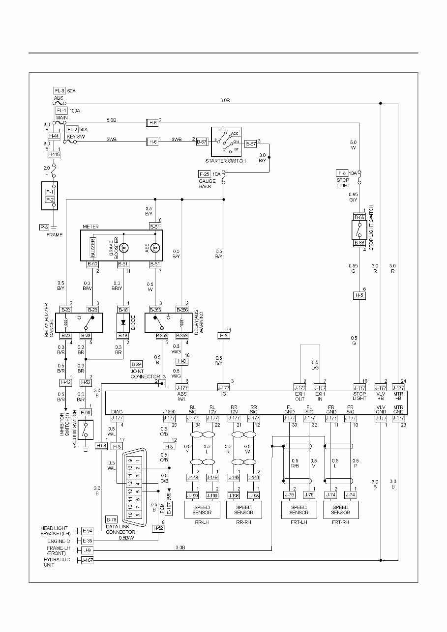
ANTI-LOCK BRAKE SYSTEM (ABS) 5A4–7 Circuit Diagram LNW35AXF000501
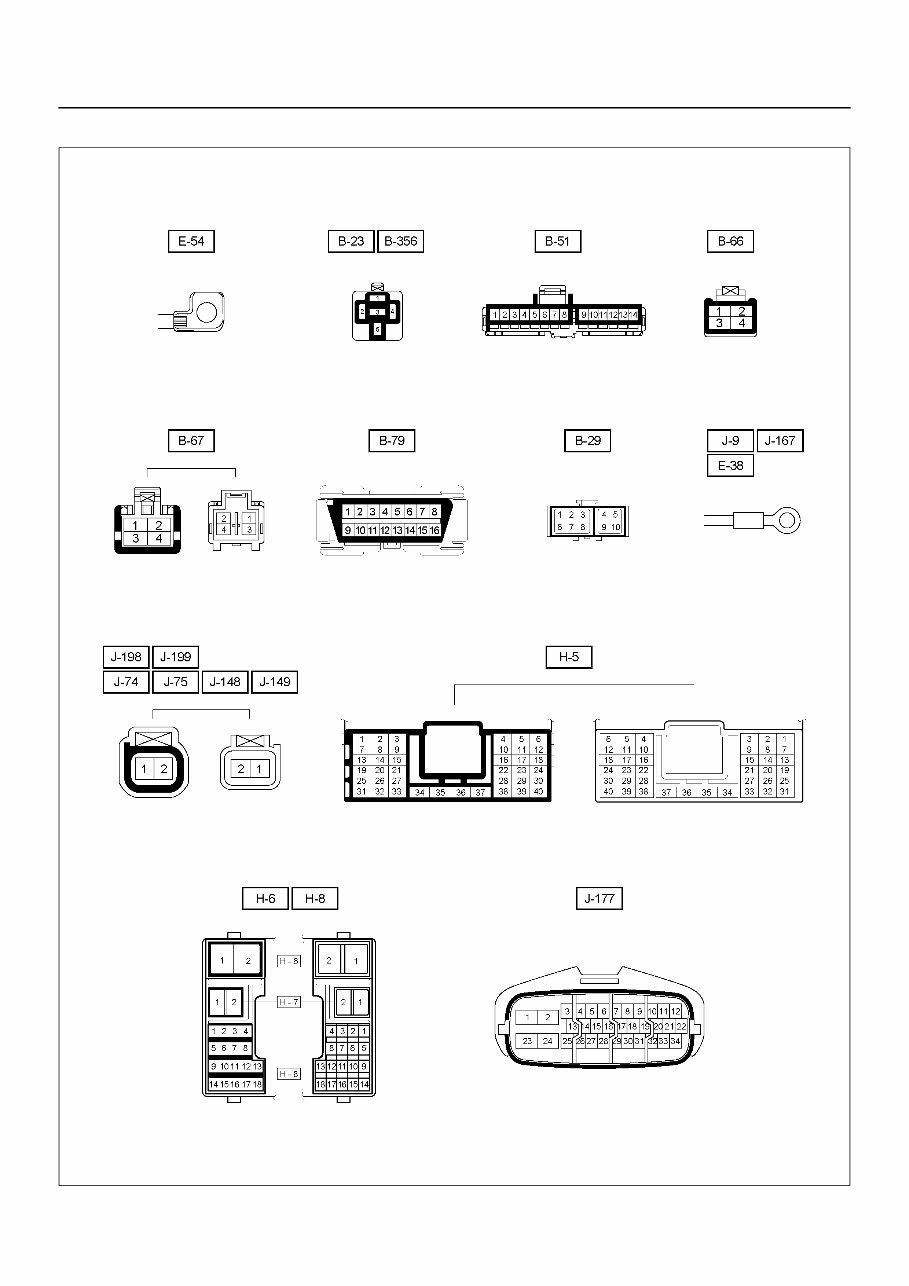
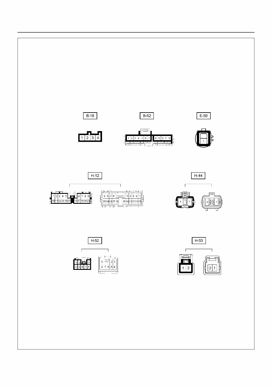
5A4–8 ANTI-LOCK BRAKE SYSTEM (ABS) Connector List LNW35AXF000201
ANTI-LOCK BRAKE SYSTEM (ABS) 5A4–9 LNW35AXF000401
5A4–10 ANTI-LOCK BRAKE SYSTEM (ABS) Part Location LNW35AXF000301
Whether you are a professional mechanic or a DIY enthusiast, this repair manual provides comprehensive troubleshooting and replacement procedures recommended by the manufacturer. It includes step-by-step instructions, clear images, and exploded-view illustrations.
Regular maintenance is essential for the durability of your truck. Over time, certain parts will wear out and require replacement. This repair manual equips you with the manufacturer's recommended troubleshooting charts and replacement procedures, enabling you to save on repairs, enhance your vehicle's reliability, and minimize visits to the repair shop.
Featuring step-by-step instructions, exploded-view illustrations, and clear images, this manual eliminates the need to search through numerous pages for specific information. It offers a convenient alternative to traditional bound manuals, allowing easy access, search, screenshot, and bookmark functions.
Additionally, it is printable and compatible with various electronic devices, including PC, Mac computers, Android and Apple smartphones, and tablets. Adobe Reader (free) is the only requirement for accessing the manual.