

Freightliner Cascadia Trucks (CA125DC/CA125SLP) Service & Repair Manual
What's Included?
Fast Download Speeds
Offline Viewing
Access Contents & Bookmarks
Full Search Facility
Print one or all pages of your manual

Electrical System and Main PDM Overview G02.01
Table of Contents
System Overview
Terms and Abbreviations .............................................................. 500
Electronic Power Distribution ........................................................... 501
Electrical Power Distribution ............................................................ 502
Powernet Distribution Box ............................................................. 503
Main Ground Junction Block (MGJB), Module 280 ........................................... 504
MEGA Fuse Junction Block (MFJB), Module 285 ............................................ 505
Powertrain PDM, Module 286 .......................................................... 506
Load Disconnect Switch, Module 293 .................................................... 507
Trailer PDM, Module 296 .............................................................. 508
PDM Diagram ...................................................................... 509
Components
Component Locations ................................................................ 600
Component Details .................................................................. 601
Troubleshooting
Possible Causes .................................................................... 700
Diagnostic Tools Required ............................................................. 701
Diagnosis .......................................................................... 702
PNDB Troubleshooting ................................................................ 703
SAM Cab and SAM Chassis Automatic Resetting Circuit Protection ............................. 704
Specifications
SAM Chassis Fuses and Relays ........................................................ 800
SAM Cab Fuses and Relays ........................................................... 801
MFJB Fuses ....................................................................... 802
Powertrain PDM and Trailer PDM Fuses and Relays ......................................... 803
Primary PNDB Fuses and Functions ..................................................... 804
Cascadia Troubleshooting Manual, September 2012

Electrical System and Main PDM Overview G02.01
500 — Terms and Abbreviations
Backbone—The main J1939 datalink wiring that lies between the two terminating resistors. It does not include
the branch circuits to each ECU or to the diagnostic connector.
CAN—Controller Area Network
CAN ID—The identifier for a specific message, which also contains the source address of the sending ECU
communicating on the J1939 datalink.
CGW—Central Gateway
Communication Protocol—A set of rules governing communication between electronic devices.
Datalink—A collection of wires, connecting system components, through which data is transmitted.
Datalink Topology—The arrangement in which the nodes (ECUs) of a datalink are connected to each other.
Diagnostic CAN—Datalink that runs from the diagnostic connector to the CGW.
Diagnostic Connector—A 9-pin diagnostic connector is used for troubleshooting the electrical system.
MFJB—MEGA
®
Fuse Junction Block
MGJB—Main Ground Junction Block
SA—Source Address; indicates numeric assignment for a device that communicates on J1939.
SAM—Signal Detect and Actuation Module
SAM Cab—Signal Detect and Actuation Module Cab ("SAM Cabin"); this ECU controls mainly cab-related func-
tionality. See G02.04 — SAM Cab for more information.
SAM Chassis—Signal Detect and Actuation Module Chassis; this ECU controls mainly chassis-related function-
ality. See G02.05 — SAM Chassis for more information.
501 — Electronic Power Distribution
The multiplexed system contains the following power distribution components:
• SAM Cab (relays and fuses), Module 32A
• SAM Chassis (relays and fuses), Module 32K
The SAM Cab and SAM Chassis are electronic control units (ECUs) that have power distribution components
such as fuses and relays on them. Refer to G02.04 — SAM Cab and G02.05 — SAM Chassis for more infor-
mation.
The SAM Chassis and SAM Cab may use self-resetting circuit protection instead of fuses for some circuits.
When the temperature of the SAM is above 170 F (77 C), it is in the tripped state. When it cools off, the circuit
will again be energized. See 704 — SAM Cab and SAM Chassis Self-Resetting Circuit Protection.
IMPORTANT: Do not change the self-resetting circuit breakers without using the special removal tool,
located inside the cover of the SAM device. See Fig. 13. Failure to use the special tool could result in
component damage.
502 — Electrical Power Distribution
Standard electrical power distribution provides battery power to the electronics system, but it is not controlled by
electronics.
Cascadia Troubleshooting Manual, September 2012 G02.01/1

G02.01 Electrical System and Main PDM Overview
The following modules are part of power distribution:
• Main Ground Junction Block (MGJB), Module 280
• MEGA Fuse Junction Block (MFJB), Module 285
• Powertrain PDM, Module 286
• PNDB, Module 33P
• Load Disconnect Switch, Module 293
• Trailer PDM, Module 296
503 — Powernet Distribution Box
The powernet distribution box (PNDB) distributes and fuses battery power to many of the vehicle loads. An op-
tional cab load disconnect switch (CLDS) is available to disconnect selected circuits. The CLDS may be located
on the chassis near the battery box or mounted so that it is operated from inside the cab. There is an LED in the
CLDS that will illuminate when power is on. The LED will flash when certain faults are detected.
Some vehicles have an auxiliary PNDB in addition to the primary PNDB. If the vehicle is equipped with a CLDS,
it controls both. An additional LED status indicator is in the CLDS on dual PNDB systems.
504 — Main Ground Junction Block (MGJB), Module 280
The MGJB is a main node for connecting a returning ground to the battery. Many of the ground circuits previ-
ously on the starter are now on the MGJB.
505 — MEGA Fuse Junction Block (MFJB), Module 285
The MFJB houses up to 5 MEGA fuses, and provides power to the engine harness, SAM Cab, SAM Chassis,
chassis-mounted trailer PDM, and an inverter.
The advantage of using an MFJB is that it provides increased robustness in the engine control and cab control
electronic systems during cranking. This is because the cab electrical system is fed from the battery through the
MFJB, and no longer from the starter. Separate starter cables provide both higher voltage levels and cleaner
power during cranking.
Additionally, there are improvements in circuit protection, and starter connection integrity (fewer circuits to con-
nect at the starter stud).
506 — Powertrain PDM, Module 286
The Powertrain Power Distribution Module (PT-PDM) is dedicated to providing battery and ignition power to the
engine (ECM), after treatment device (ATD), transmission (TCU), as well as other powertrain-related circuits. It is
mounted in the engine compartment, above the quarter fender on the driver side of the vehicle.
507 — Load Disconnect Switch, Module 293
The load disconnect switch is used to disconnect (or open) the connection between the battery and the MFJB.
Turning the load disconnect switch to the off position does not disconnect the batteries from the starter.
NOTE: If the engine is running, turning the load disconnect switch to the OFF position will not shut off
the engine. The powertrain PDM still gets battery voltage from the emergency power feed on the SAM
system.
Cascadia Troubleshooting Manual, September 2012 G02.01/2
Electrical System and Main PDM Overview G02.01
The load disconnect switch is mounted on one of three locations:
• Inside the cab on the left side of the driver’s seat on a left-hand-drive vehicle.
• On the battery box.
• Outboard-mounted on the left frame rail.
508 — Trailer PDM, Module 296
The trailer PDM is used to supply trailer power to the chassis-mounted trailer receptacles. The SAM Chassis
supplies control outputs to the remote trailer PDM. The trailer PDM is powered through the vehicle’s battery sys-
tem. The SAM Chassis does not supply battery power to the trailer PDM. See Fig. 1.
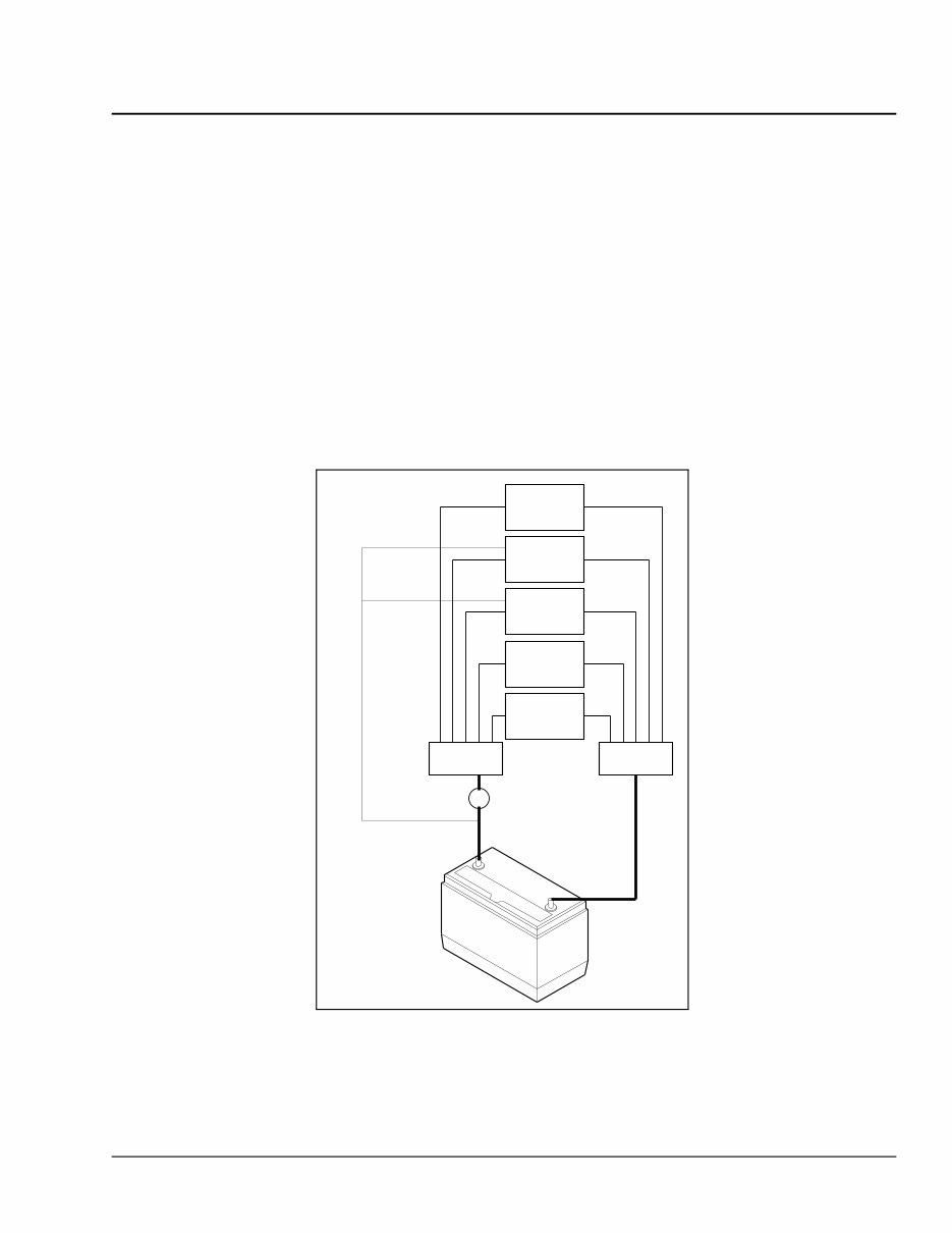
509 — PDM Diagram
MFJB MGJB
Load Disconnect
Switch
Emergency Power Feed
PT-PDM
SAM
Cab
SAM
Chassis
Trailer
PDM
Inverter
04/24/2007 f545016
Fig. 1, PDM Diagram
Cascadia Troubleshooting Manual, September 2012 G02.01/3
G02.01 Electrical System and Main PDM Overview
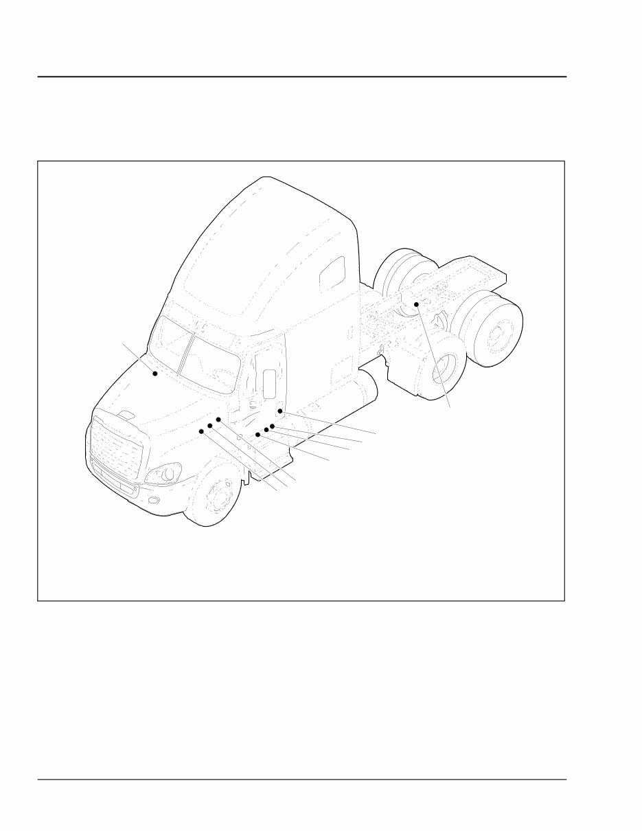
600 — Component Locations
f001175a 02/27/2012
2
1
4
9
8
6
5
3
7
1. SAM Cab
2. Powertrain PDM (PT-PDM)
3. Powernet Distribution Box (PNDB)
4. SAM Chassis
5. Main Ground Junction Block (MGJB)
6. MEGA Fuse Junction Block (MFJB)
7. Cab Load Disconnect Switch (optional location)
8. Cab Load Disconnect Switch (optional location)
9. Trailer PDM
Fig. 2, Component Locations
Cascadia Troubleshooting Manual, September 2012 G02.01/4
You're Reading a Preview
What's Included?
Fast Download Speeds
Offline Viewing
Access Contents & Bookmarks
Full Search Facility
Print one or all pages of your manual
$39.99
$51.99
Viewed 11 Times Today


Secure transaction
What's Included?
Fast Download Speeds
Offline Viewing
Access Contents & Bookmarks
Full Search Facility
Print one or all pages of your manual
$39.99
$51.99
This service manual for Freightliner Cascadia Trucks (CA125DC/CA125SLP) is suitable for both first-time owners/amateurs and professional technicians. It presents the procedures and service information in an easy-to-read format, providing comprehensive details to perform maintenance and repairs accurately. Keeping this manual on hand and referring to it frequently is advised, as regular preventive maintenance can help avoid premature equipment failure and reduce unnecessary repair costs.
- Models Covered:
- CA125DC
- CA125SLP
Manual Contents:
- General Information
- Engine
- Air Intake
- Air Compressor
- Alternators and Starters
- Engine Cooling/Radiator
- Clutch
- Transmission
- Throttle Control
- Frame and Frame Components
- Suspension
- Front Axle
- Rear Axle
- Wheels and Tires
- Driveline
- Brakes
- Steering
- Fuel
- Exhaust
- Electrical, Instruments, and Controls
- Cab
- Doors
- Windshield Wipers and Washer
- Heater and Air Conditioner
- Hood, Grille, and Cab Fenders
- Fire Suppression Systems
- Seats and Restraint Systems
- Paint
File Format: PDF
Compatibility: All Versions of Windows & Mac
Language: English
Requirements: Adobe Reader & Win


