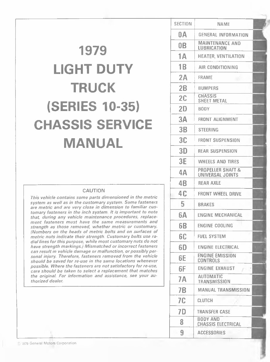
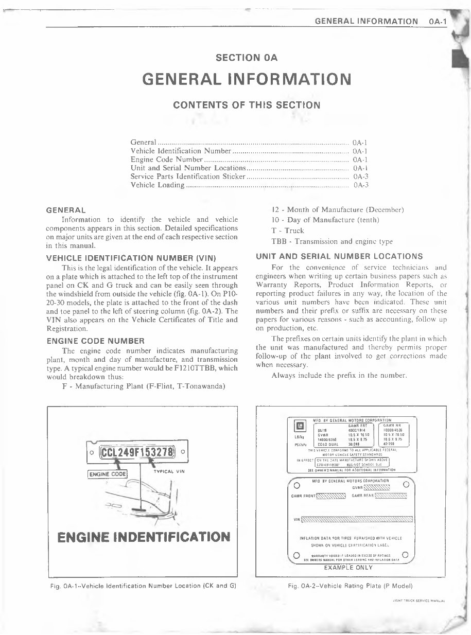
T GENERAL INFORMATION OA-1 SECTION OA GENERAL INFORMATION CONTENTS OF THIS SECTION General............................................................................................. OA-1 Vehicle Identification Number........................................................ OA-1 Engine Code Number...................................................................... OA-1 Unit and Serial Number Locations................................................. OA-1 Service Parts Identification Sticker................................................. OA-3 Vehicle Loading................................................... ........................... OA-3 GENERAL Information to identify the vehicle and vehicle components appears in this section. Detailed specifications on major units are given at the end of each respective section in this manual. VEHICLE IDENTIFICATION NUMBER (VIN) This is the legal identification of the vehicle. It appears on a plate which is attached to the left top of the instrument panel on CK and G truck and can be easily seen through the windshield from outside the vehicle (fig. OA-1). On P10- 20-30 models, the plate is attached to the front of the dash and toe panel to the left of steering column (fig. 0A-2). The VIN also appears on the Vehicle Certificates of Title and Registration. ENGINE CODE NUMBER The engine code number indicates manufacturing plant, month and day of manufacture, and transmission type. A typical engine number would be F1210TTBB, which would breakdown thus: F - Manufacturing Plant (F-Flint, T-Tonawanda) 12 - Month of Manufacture (December) 10 - Day of Manufacture (tenth) T - Truck TBB - Transmission and engine type UNIT AND SERIAL NUMBER LOCATIONS For the convenience of service technicians and engineers when writing up certain business papers such as Warranty Reports, Product Information Reports, or reporting product failures in any way, the location of the various unit numbers have been indicated. These unit numbers and their prefix or suffix are necessary on these papers for various reasons - such as accounting, follow up on production, etc. The prefixes on certain units identify the plant in which the unit was manufactured and thereby permits proper follow-up of the plant involved to get corrections made when necessary. Always include the prefix in the number. o (CCL249F1532781 ° | ENGINE CODE| ------------------------- TYPICAL VIN ENGINE INDENTIFICATION MFD. BY GENERAL MOTORS CORPORATION LB/kg PSI /kPa GAWR FRT 08/78 4000/1814 GVWR 10.5 X 16.50 14000/6350 16.5 X 9.75 COLO DUAL 36/248 GAWR RR 10000/4536 10.5 X 16.50 16 6 X 9 75 42/290 THIS VEHICLE CONFORMS TO ALL APPLICABLE FEDERAL MOTOR VEHICLE SAFETY STANDARDS IN EFFECT [ ON THE DATE MANUFACTURE SHOWN ABOVE 1 1 CZQI691100001 8US-N0T SCHOOL BUS I SEE OWNER S MANUAL FOR A0OITIONAL INFORMATION fZ L MFD BY GENERAL MOTORS CORPORATION O GVWRi^^ U GAWR FRONT^ S ^ ^ GAWR REAR VN INFLATION DATA FOR TIRES FURNISHED WITH VEHICLE SHOWN ON VEHICLE CERTIFICATION LABEL Q WARRANTY VOIDED IF LOADED IN EXCESS OF RATINGS Q . SEE OWNERS MANUAL FOR OTHER 10A0ING AND INFLATION DATA EXAMPLE ONLY Fig. OA-1--Vehicle Identification Number Location (CK and G) Fig. OA-2--Vehicle Rating Plate (P Model) LIGHT TRUCK SERVICE MANUAL
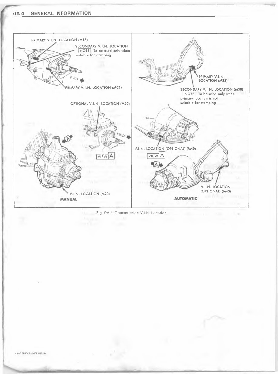
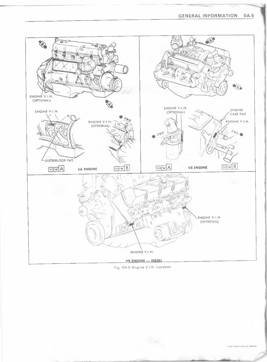
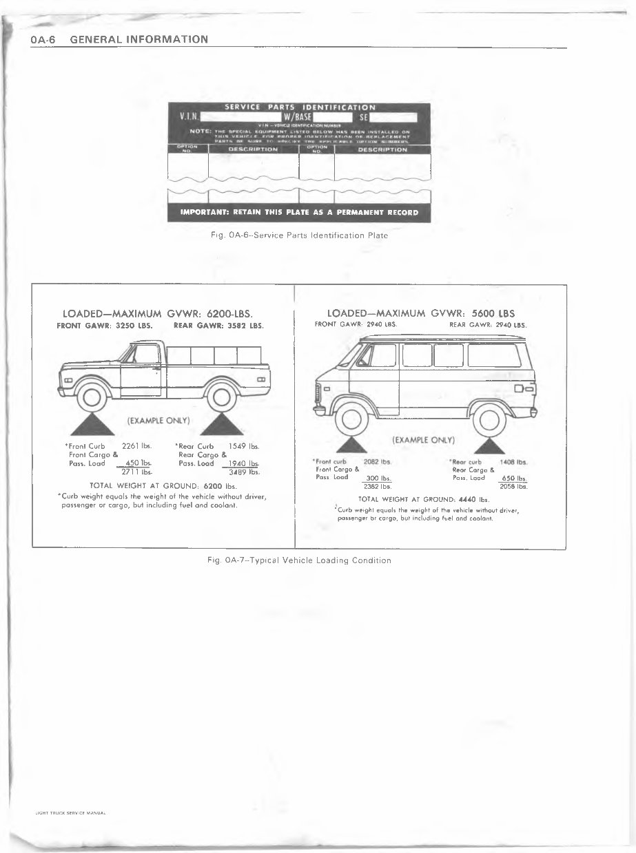
GENERAL INFORMATION OA-3 Axles Chevrolet Built • On 10 Series, the Code is stamped on Top of Right Rear Axle Tube. • On 20-30 Series, the Code is stamped on Top of the Right Rear Axle Tube. Dana Built • On Front Axles, code is stamped on Top Rear of Left Axle Tube. • On Rear Axles, code is stamped on Rear Surface of Right Axle Tube. Transmissions (Fig. 0A-4) • On 3-Speed Transmissions (except Tremec), the Unit Number is located on Lower Left Side of Case Just Below Cover. • On Tremec Transmissions, Unit Number is located on Upper Left Attachment Case (Top Side). • On Muncie 4-Speeds, Unit Number is located on Rear Face of Case below Retainer. • On New Process 203 and 205 model 4-wheel drive transfer case, a build date is on tag attached to front face of transfer case. • On Muncie Model 203 4-wheel drive transfer case, a build date is on front face of transfer case above output shaft. • On Automatic 350 Transmission, Unit Number is Located on Right Rear Vertical Surface of Oil Pan. • On the Automatic 400 Transmission, Serial Number is Located on the Light Blue Plate on the Right Side of the Transmission. Engines (Fig. 0A-5) • 6-Cylinder Engine Unit Number Located on Pad at Right Hand Side of Cylinder Block at Rear of Distributor. • 8-Cylinder Gasoline Engine Code is (305, 350, 400 CID) Located on Pad immediately forward of right hand cylinder head. • 8-Cylinder Gasoline Engine (454 CID) Code is located on a pad of the front top center of the engine block immediately forward of the inlet manifold. • 8-Cylinder Diesel Engine Code is on a label located on rear face of the left valve cover. Generators Generator Unit Serial Number is located on the Drive End Frame Below the Part Number. Batteries Battery Code Number is Located on Cell Cover Top of Battery. Starters Starter Serial Number and Production Date are Stamped on Outer Case, Toward Rear. SERVICE PARTS IDENTIFICATION STICKER The Service Parts Identification Sticker (fig. OA-6) is provided on all Truck models. On C and K models, the identification sticker be located on the inside of the glove box door or on G model, the sticker will be located on an inner hood panel surface. On P models, the sticker is located on a inner body panel. The plate lists the vehicle identification number, wheelbase, and all Production options or Special Equipment on the vehicle when it was shipped from the factory including paint information. ALWAYS REFER TO THIS INFORMATION WHEN ORDERING PARTS. VEHICLE LOADING Vehicle loading must be controlled so weights do not exceed the numbers shown on the Vehicle Identification Number and/or Rating Plate for the vehicle. A typical example of a truck in a loaded condition is shown in Figure 0A-7. Note that the axle or GVW capabilities are not exceeded. LIGHT TRUCK SERVICE MANUAL
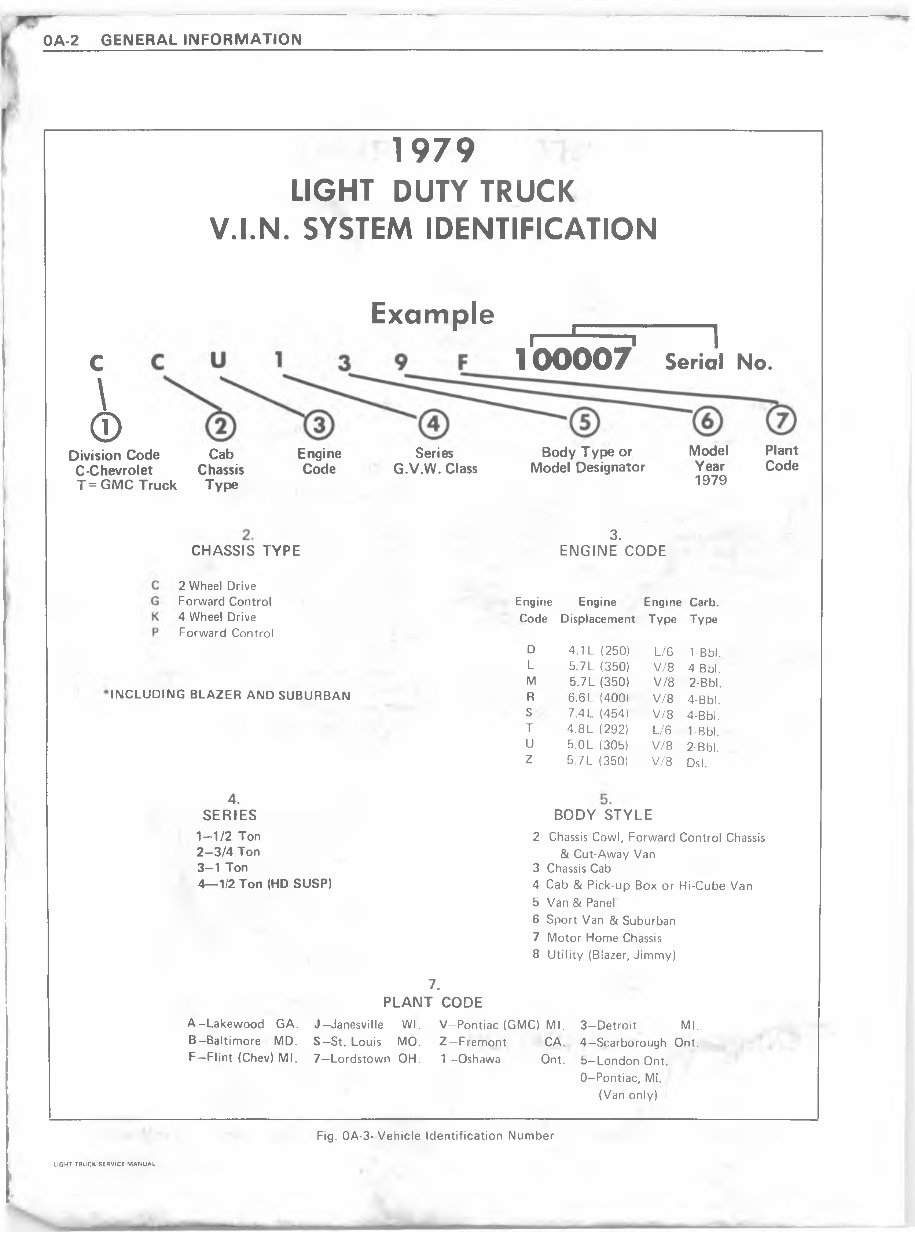
OA-4 GENERAL INFORMATION PRIMARY V.I.N . LOCATION (M15) SECONDARY V.I.N. LOCATION [ NOTE | To be used only when suitable for stamping PRIMARY V .I.N . LOCATION (M38) PRIMARY V.I.N. LOCATION (MCI) SECONDARY V.I.N. LOCATION (M38) [ NOTE j To be used only when primary location is not suitable for stamping OPTIONAL V.I.N. LOCATION (M20) V.I.N. LOCATION (OPTIONAL) (M40) [ ww | a ] ^ VIEW V.I.N. LOCATION (OPTIONAL) (M40) V.I.N. LOCATION (M20) Fig. 0A-4--Transmission V.I.N. Location LIGHT TRUCK SERVICE MANUAL
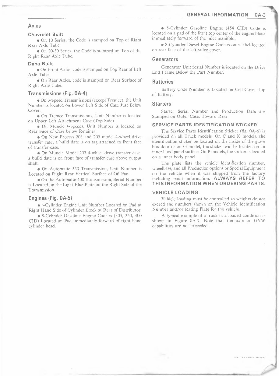
ENGINE V.I.N (OPTIONAL) ENGINE V.I.N (OPTIONAL) ENGINE CASE PAD ENGINE V.I.N ENGINE V.I.N ENGINE V.I.N (OPTIONAL) DISTRIBUTOR PAD [ view I view ] A V8 ENGINE VIEW L6 ENGINE VIEW ENGINE V.I.N (OPTIONAL) ENGINE V.I.N V8 ENGINE — DIESEL GENERAL INFORMATION OA-5 Fig. OA-5-Engine V.I.N. Location LIGHT TRUCK SERVICE MANUAL
OA-6 GENERAL INFORMATION IMPORTANT: RETAIN THIS PLATE AS A PERMANENT RECORD Fig. OA-6-Service Parts Identification Plate LOADED-MAXIMUM GVWR: 5600 LBS FRONT GAWR: 2940 IBS. REAR GAWR: 2940 LBS. Front Cargo & Rear Cargo & Pass Load 30O lbs. Pass. Load 650 lbs. 2382 lbs. 2058 lbs. TOTAL WEIGHT AT GROUND: 4440 lbs. ’ Curb weight equals the weight of the vehicle without driver, passenger Or cargo, but including fuel and coolant. LOADED-MAXIMUM GVWR: 6200-LBS. FRONT GAWR: 3250 LBS. REAR GAWR: 3582 LBS. TOTAL WEIGHT AT GROUND: 6200 lbs. ’ Curb weight equals the weight of the vehicle without driver, passenger or cargo, but including fuel and coolant. ‘ Front Curb 2261 lbs. Front Cargo & Pass. Load 450 lbs. 2711 lbs- ’ Rear Curb 1549 lbs. Rear Cargo & Pass. Load 1940 lbs- 3489 lbs. Fig. 0A-7--Typical Vehicle Loading Condition LIGHT TRUCK SERVICE MANUAL
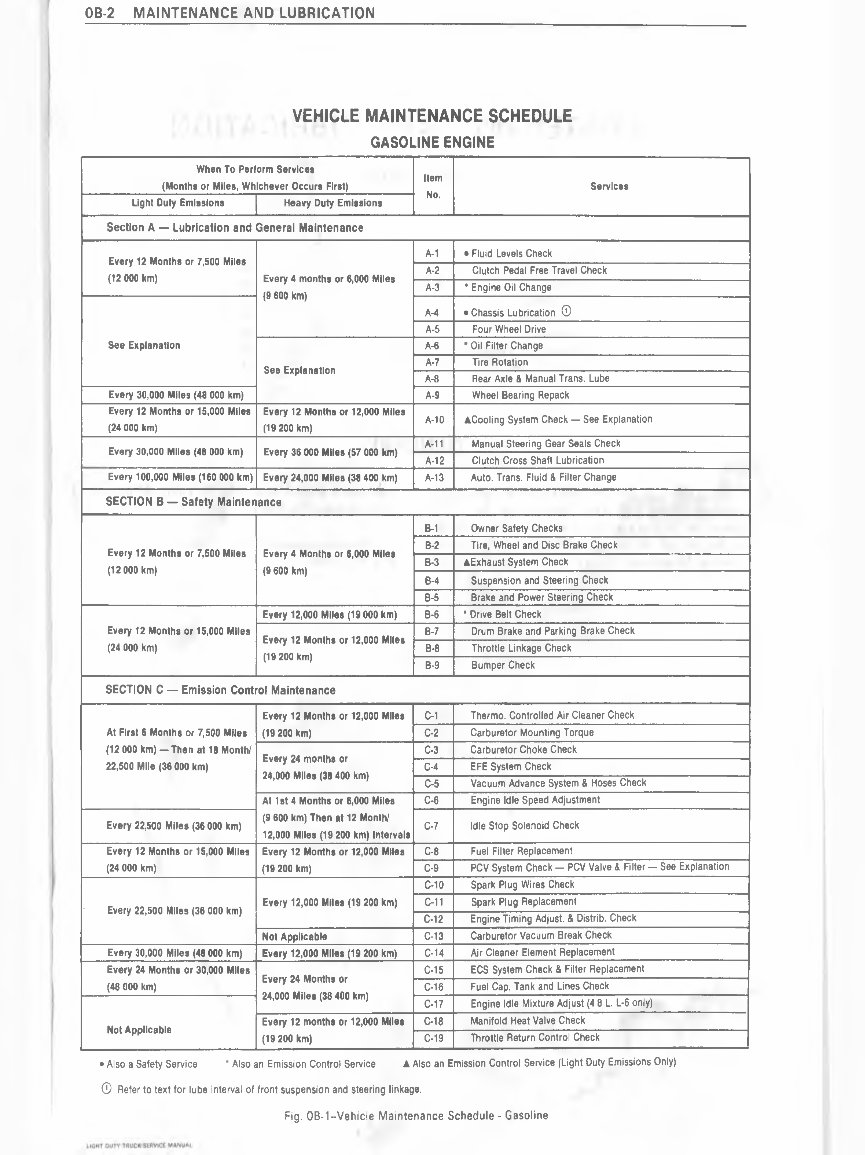
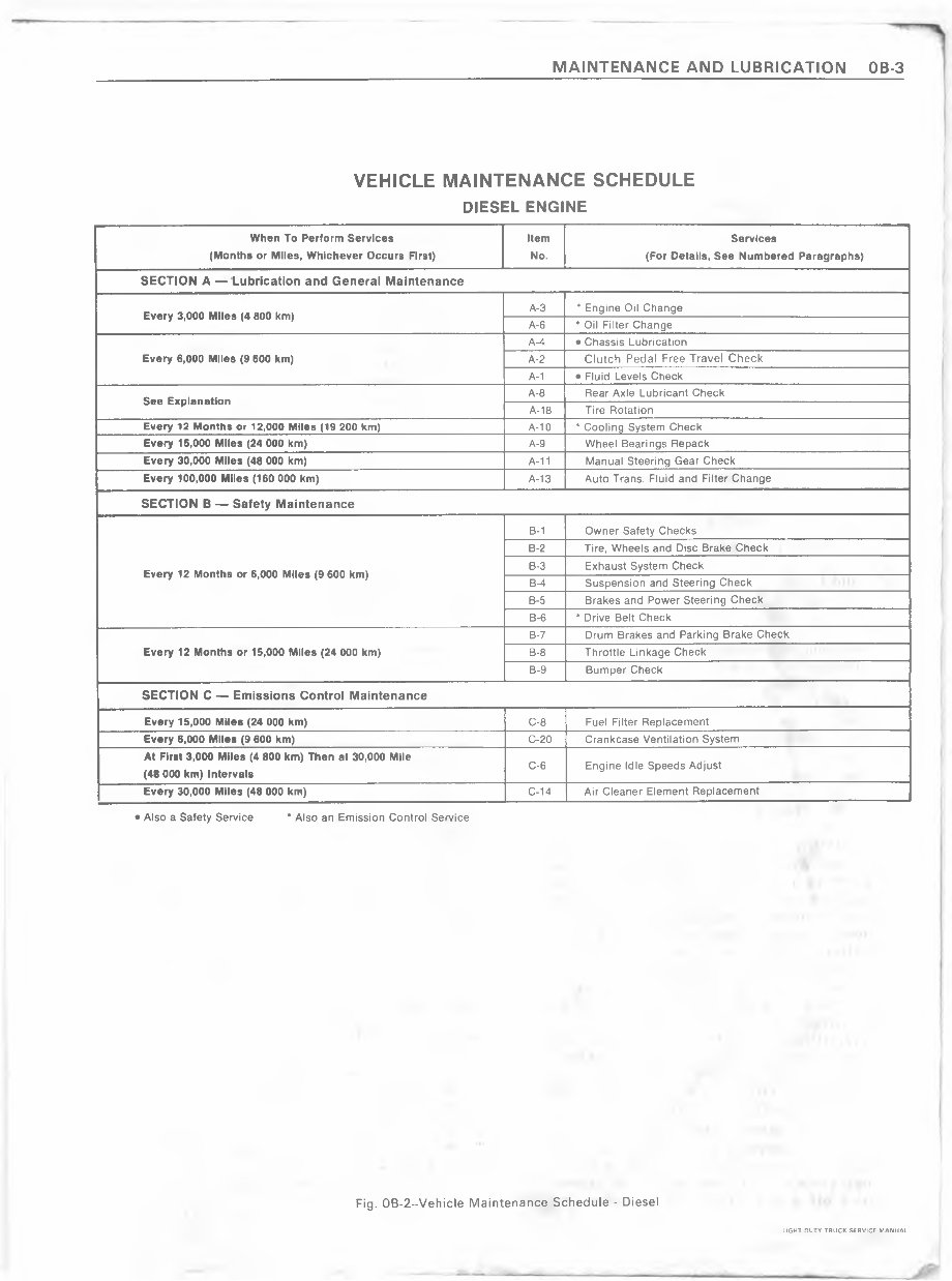
MAINTENANCE AND LUBRICATION OB-1 SECTION OB MAINTENANCE AND LUBRICATION M CONTENTS General........................................................................................ .OB-1 Maintenance Schedule................................................................ .OB-2 Lubricant and General Maintenance ............................... ....... .OB-4 Safety Maintenance................................................................... .OB-13 Emission Control....................................................................... .OB-14 Specifications......................... ................. ............................. ..... .OB-16 Recommended Fluids and Lubricants..................................... .OB-16 Fluid Capacities........ .................................................... ........... .OB-17 GENERAL The maintenance schedule for a gasoline engine follows two basic formats, Light Duty Emissions and Heavy Duty Emissions. The major difference between the two schedules is the intervals for service and Section "C", Emission Control Maintenance (fig. OB-1). A separate vehicle maintenance schedule is provided for those vehicles with a V-8 diesel engine (fig. OB-2). The maintenance schedule is provided in the glove box with the vehicle. LIGHT DUTY TRUCK SERVICE MANUAL
MAINTENANCE AND LUBRICATION OB-3 VEHICLE MAINTENANCE SCHEDULE DIESEL ENGINE When To Perform Services (Months or Miles, Whichever Occurs First) Item No. Services (For Details, See Numbered Paragraphs) SECTION A — Lubrication and General Maintenance Every 3,000 Miles (4 800 km) A-3 * Engine Oil Change A-6 * Oil Filter Change Every 6,000 Miles (9 600 km) A-4 • Chassis Lubrication A-2 Clutch Pedal Free Travel Check A-1 • Fluid Levels Check See Explanation A-8 Rear Axle Lubricant Check A-18 Tire Rotation Every 12 Months or 12,000 Miles (19 200 km) A-10 * Cooling System Check Every 15,000 Miles (24 000 km) A-9 Wheel Bearings Repack Every 30,000 Miles (48 000 km) A-11 Manual Steering Gear Check Every 100,000 Miles (160 000 km) A-13 Auto Trans. Fluid and Filter Change SECTION B — Safety Maintenance Every 12 Months or 6,000 Miles (9 600 km) B-1 Owner Safety Checks B-2 Tire, Wheels and Disc Brake Check B-3 Exhaust System Check B-4 Suspension and Steering Check B-5 Brakes and Power Steering Check B-6 * Drive Belt Check Every 12 Months or 15,000 Miles (24 000 km) B-7 Drum Brakes and Parking Brake Check B-8 Throttle Linkage Check B-9 Bumper Check SECTION C — Emissions Control Maintenance Every 15,000 Miles (24 000 km) C-8 Fuel Filter Replacement Every 6,000 Miles (9 600 km) C-20 Crankcase Ventilation System At First 3,000 Miles (4 800 km) Then at 30,000 Mile (48 000 km) Intervals C-6 Engine Idle Speeds Adjust Every 30,000 Miles (48 000 km) C-14 Air Cleaner Element Replacement • Also a Safety Service * Also an Emission Control Service Fig. 0B-2--Vehicle Maintenance Schedule - Diesel LIGHT DUTY TRUCK SERVICE MANUAL
The 1978 Chevrolet Trucks Service & Repair Manual is an indispensable resource for maintaining and repairing your classic Chevy truck. Developed by Chevrolet, this manual provides detailed instructions and precise specifications for accurate maintenance and effective troubleshooting.
Inside, you'll find comprehensive procedures for routine maintenance tasks such as oil changes, brake adjustments, and tire rotations. The manual also covers more complex repairs, including engine diagnostics, transmission servicing, and electrical system troubleshooting. Detailed diagrams and illustrations help identify components and ensure that repairs are performed accurately and efficiently.
Designed for professional technicians and experienced DIY enthusiasts, this manual delivers the critical technical information needed to keep your 1978 Chevrolet truck running smoothly. By following the detailed guidance provided, you can ensure long-term reliability and optimal performance, preserving the operational lifespan of your vintage vehicle.
Printable: Yes Language: English Compatibility: Pretty much any electronic device, incl. PC & Mac computers, Android and Apple smartphones & tablet, etc. Requirements: Adobe Reader (free)