ELECTRICAL
8.1
CHAPTER 8
ELECTRICAL
8
GENERAL INFORMATION . . . . . . . . . . . . . . . . . . . . . . . . . . . . . . . . . . . . . . . . . . . . . . . . 8.2
SPECIAL TOOLS . . . . . . . . . . . . . . . . . . . . . . . . . . . . . . . . . . . . . . . . . . . . . . . . . . . . . . . 8.2
BATTERY MAINTENANCE / TESTING . . . . . . . . . . . . . . . . . . . . . . . . . . . . . . . . . . . . . . 8.2
ELECTRICAL SERVICE NOTES . . . . . . . . . . . . . . . . . . . . . . . . . . . . . . . . . . . . . . . . . . . 8.2
GENERAL WIRE COLOR FUNCTION . . . . . . . . . . . . . . . . . . . . . . . . . . . . . . . . . . . . . . . 8.2
OVERHEAT CONTROL CIRCUIT OPERATION . . . . . . . . . . . . . . . . . . . . . . . . . . . . . . . 8.2
48 VOLT FUSE AND RELAY LOCATION . . . . . . . . . . . . . . . . . . . . . . . . . . . . . . . . . . . . 8.3
FUSE, RELAY, AND DIODE SUB-PANEL (EV-LSV) . . . . . . . . . . . . . . . . . . . . . . . . . . . . 8.3
FLASHER MODULE (EV-LSV) . . . . . . . . . . . . . . . . . . . . . . . . . . . . . . . . . . . . . . . . . . . . . 8.3
12 VOLT AUXILIARY POWER OUTLET . . . . . . . . . . . . . . . . . . . . . . . . . . . . . . . . . . . . . 8.4
AUXILIARY TERMINAL BOARD / SUB-HARNESS POWER SUPPLY (EV-LSV) . . . . . 8.4
SWITCHES / CONTROLS . . . . . . . . . . . . . . . . . . . . . . . . . . . . . . . . . . . . . . . . . . . . . . . . . 8.5
HEADLIGHT SWITCH . . . . . . . . . . . . . . . . . . . . . . . . . . . . . . . . . . . . . . . . . . . . . . . . . . . 8.5
AWD / 2WD / TURF SWITCH . . . . . . . . . . . . . . . . . . . . . . . . . . . . . . . . . . . . . . . . . . . . . . 8.6
DIRECTION SELECTOR SWITCH (F / N / R) . . . . . . . . . . . . . . . . . . . . . . . . . . . . . . . . . 8.7
DRIVE MODE SWITCH (HIGH, MAX RANGE, LOW) . . . . . . . . . . . . . . . . . . . . . . . . . . . 8.8
DIFFERENTIAL SOLENOID / SOLENOID DRIVER MODULE . . . . . . . . . . . . . . . . . . . . 8.9
BRAKE LIGHT SWITCH (HYDRAULIC) PARKING BRAKE SWITCH . . . . . . . . . . . . . 8.10
INDICATOR LIGHT CIRCUITS / INDICATOR LAMP REPLACEMENT . . . . . . . . . . . . . 8.11
INDICATOR LIGHTS . . . . . . . . . . . . . . . . . . . . . . . . . . . . . . . . . . . . . . . . . . . . . . . . . . . 8.12
BATTERY DISCHARGE INDICATOR . . . . . . . . . . . . . . . . . . . . . . . . . . . . . . . . . . . . . . 8.13
CHARGE STATUS INDICATOR . . . . . . . . . . . . . . . . . . . . . . . . . . . . . . . . . . . . . . . . . . . 8.13
DIGITAL WRENCH‘ DIAGNOSTIC SOFTWARE . . . . . . . . . . . . . . . . . . . . . . . . . . . . . . 8.14
ACCELERATOR PEDAL POSITION SENSOR . . . . . . . . . . . . . . . . . . . . . . . . . . . . . . . 8.14
ALL WHEEL DRIVE (AWD) COIL AND AWD SYSTEM . . . . . . . . . . . . . . . . . . . . . . . . . 8.14
HEADLIGHTS . . . . . . . . . . . . . . . . . . . . . . . . . . . . . . . . . . . . . . . . . . . . . . . . . . . . . . . . . 8.15
HEADLIGHT ADJUSTMENT . . . . . . . . . . . . . . . . . . . . . . . . . . . . . . . . . . . . . . . . . . . . . 8.15
HEADLIGHT BULB REPLACEMENT . . . . . . . . . . . . . . . . . . . . . . . . . . . . . . . . . . . . . . . 8.16
HEADLIGHT HOUSING REMOVAL . . . . . . . . . . . . . . . . . . . . . . . . . . . . . . . . . . . . . . . . 8.16
TAIL LIGHT / BRAKE LIGHT . . . . . . . . . . . . . . . . . . . . . . . . . . . . . . . . . . . . . . . . . . . . . . 8.17
48 VDC - 13.5VDC CONVERTER . . . . . . . . . . . . . . . . . . . . . . . . . . . . . . . . . . . . . . . . . . 8.17
SYSTEM WIRING DIAGRAMS . . . . . . . . . . . . . . . . . . . . . . . . . . . . . . . . . . . . . . . . . . . . 8.18
BATTERY SYSTEM WIRING DIAGRAM . . . . . . . . . . . . . . . . . . . . . . . . . . . . . . . . . . . . 8.18
DRIVE MOTOR ENCODER SYSTEM WIRING DIAGRAM . . . . . . . . . . . . . . . . . . . . . . 8.19
BATTERY CHARGING SYSTEM WIRING DIAGRAM . . . . . . . . . . . . . . . . . . . . . . . . . . 8.20
AUXILIARY (ACCESSORY) BATTERY SYSTEM WIRING DIAGRAM . . . . . . . . . . . . . 8.21
13.5 VOLT SYSTEM WIRING DIAGRAM . . . . . . . . . . . . . . . . . . . . . . . . . . . . . . . . . . . . 8.22
LIGHTING SYSTEM WIRING DIAGRAM . . . . . . . . . . . . . . . . . . . . . . . . . . . . . . . . . . . . 8.23
PARKING BRAKE SYSTEM WIRING DIAGRAM . . . . . . . . . . . . . . . . . . . . . . . . . . . . . . 8.24
AWD SYSTEM WIRING DIAGRAM . . . . . . . . . . . . . . . . . . . . . . . . . . . . . . . . . . . . . . . . 8.25
AWD / 2WD / TURF SWITCH CONTACTS . . . . . . . . . . . . . . . . . . . . . . . . . . . . . . . . . . 8.26
DIRECTION SELECTOR - SYSTEM WIRING DIAGRAM . . . . . . . . . . . . . . . . . . . . . . . 8.27
DIRECTION SELECTOR SWITCH CONTACTS . . . . . . . . . . . . . . . . . . . . . . . . . . . . . . 8.28
DRIVE MODE (HIGH / MAX RANGE / LOW) - SYSTEM WIRING DIAGRAM . . . . . . . . 8.29
ACCELERATOR PEDAL POSITION SENSOR - SYSTEM WIRING DIAGRAM . . . . . . 8.30
MAIN FUSE BOX . . . . . . . . . . . . . . . . . . . . . . . . . . . . . . . . . . . . . . . . . . . . . . . . . . . . . . 8.31
SUB-HARNESS FUSE BOX (EV-LSV) . . . . . . . . . . . . . . . . . . . . . . . . . . . . . . . . . . . . . . 8.32
TURN SIGNAL / HAZARD CIRCUIT - OPERATIONAL OVERVIEW . . . . . . . . . . . . . . . 8.33
TURN SIGNAL / HAZARD / HORN CONTROL SWITCH CONTACTS / DIAGNOSTICS8.34
HORN CIRCUIT - OPERATIONAL OVERVIEW . . . . . . . . . . . . . . . . . . . . . . . . . . . . . . . 8.35
HORN CIRCUIT WIRING DIAGRAM . . . . . . . . . . . . . . . . . . . . . . . . . . . . . . . . . . . . . . . 8.35
DIGITAL WRENCH TROUBLE CODE LIST . . . . . . . . . . . . . . . . . . . . . . . . . . . . . . . . . . 8.36
DIGITAL WRENCH TROUBLE CODE LIST (CONT.) . . . . . . . . . . . . . . . . . . . . . . . . . . 8.37
8.2
ELECTRICAL
© Copyright 2010 Polaris Sales Inc. 2011 POLARIS EV - LSV Service Manual 9923008
GENERAL INFORMATION
Special Tools
Battery Maintenance / Testing
See Chapter 1 “General / Battery” for battery service
procedures, maintenance, and connections.
Electrical Service Notes
Note the following when diagnosing an electrical problem:
• BATTERY INFORMATION - All battery information
including Safety, Maintenance, Service, and Testing is
in Chapter 1 General Information and Battery .
• FLOATING CHASSIS - Unless the battery charger is
connected to a wall outlet, the chassis on the POLARIS
EV-LSV is not used as a conductor and is not at ground
potential. The ground wire in the wire harness must be
used as a ground reference for your meter or when
instructed to connect a wire on the vehicle to “ground”.
• Do not service the electrical system when charging the
batteries. The chassis is at ground potential when the
charger of the vehicle is connected to a wall outlet,
which increases the chance of an electrical short.
• 48 VOLT FUSES AND RELAYS - Some fuses and
relays are 48 Volt and must not be substituted with
similar looking 12 volt parts.
• Disconnect the Main Power Connector (See Chapter
1) before disconnecting any electrical component.
The Main Power Connector should be the last
connection made after servicing the vehicle.
• Refer to wiring diagram or the system break-out
diagram for electrical component resistance
specifications and location on the vehicle.
• When measuring resistance of a component that has a
resistance value under 10 Ohms, remember to subtract
meter lead resistance from the reading. Connect the
leads together and record the resistance. The true
resistance is equal to tested value minus lead resistance.
• Be sure your meter leads are in the proper jack for the
test being performed (i.e. 10A jack for current
readings). Refer to the Owner’s Manual included with
your meter for more information.
• Voltage, amperage, and resistance values included in
this manual are obtained with a Fluke™ 77 Digital
Multimeter (PV-43568) or an equivalent Fluke meter.
Readings obtained with other meters may differ.
• Pay attention to the prefix on the multimeter reading (K,
M, etc.) and the position of the decimal point.
• For resistance readings, isolate the component being
tested by disconnecting it from the wiring harness or
power supply.
• Verify battery voltage and general battery condition.
• Inspect battery and contactor terminal cleanliness,
condition, and fastener torque.
• Inspect all connections at the controller
• Connectors in a circuit - Separate the connector and
closely inspect terminal pins or sockets for corrosion.
Verify all pins are aligned in mating connectors. Check
wires closely to be sure pins and sockets are secure
(locked in) the connector housing.
• Secure all wiring to prevent contact with sharp edges or
moving parts after service.
General Wire Color Function
Following is a description of wire color function for the main
circuits on the POLARIS EV-LSV. Some exceptions may occur.
Always refer to the system wiring schematics or to the main
chassis and sub-harness schematics for reference.
Overheat Control Circuit Operation
Overheating of the controller or drive motor will illuminate the
TEMP light on the indicator light panel. When the TEMP lamp
is on, the controller will reduce performance or terminate power
delivery (if severe overheating exists) until the overheat
condition has passed. Operation will return to normal when the
controller and /or motor has cooled.
Part Number Tool Description
PV-43568 Fluke™ 77 Digital Multimeter
Commercially
Available
Battery Hydrometer (Temperature
compensated with numerically graduated
scale) (Not floating ball type)
PU-47063 Digital Wrench™ Diagnostic Software
PU-47471 Digital Wrench™ SmartLink Module Kit
WIRE COLOR PRIMARY CIRCUIT FUNCTION
RD/WH 48 Volt Switched Power
RD/BK 13.5 Volt Switched Power
BN Ground
OR/BK 13.5 Volt Switched Accy Power
PK/BK 13.5 Volt Constant Accy Power
GY AWD (+)
BN/WH AWD Switching (Low Side)
RD/YE Lighting / Sub Harness Switched Power
OR/RD
Park Brake Monitor Circuit
(Grounded in Park)
VT Reverse Monitor (Grounded in Reverse)
8.3
ELECTRICAL
8
© Copyright 2010 Polaris Sales Inc. 2011 POLARIS EV - LSV Service Manual 9923008
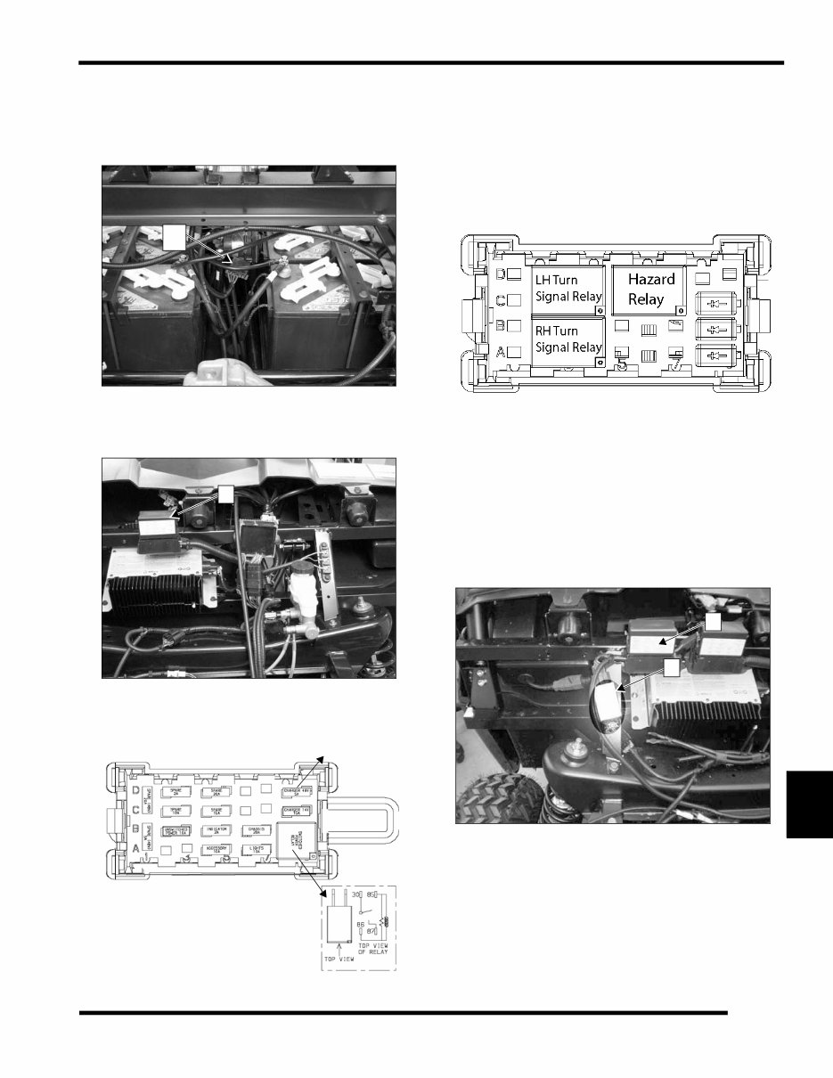
48 Volt Fuse and Relay Location
There are three 48 volt / 20 amp fuses located in fuse block (A)
and one spare 20 amp fuse in the fuse block (B) located under
the hood. Open cargo box for access to fuse block (A).
A 48 volt relay and a 48 volt fuse (fuse is for accessory battery
charge circuit) are located in the main fuse box (B) under the
hood.
Fuse, Relay, and Diode Sub-Panel (EV-LSV)
A sub-panel fuse box is located just outboard of the main fuse
box under the hood on the passenger side. This panel contains
the (3) relays and (3) diodes required for turn signal and, brake
light, and hazard operation. Refer to system diagnostics at the
end of this chapter to troubleshoot these systems.
Flasher Module (EV-LSV)
Flasher Module location (C).
Sub-harness fuse box location (D).
IMPORTANT: Disconnect the Main Power Connector
(see chapter 1) before disconnecting any electrical
component. The Main Power Connector is the first to
disconnect and the last to connect when servicing the
electrical system.
A
B
48 Volt Fuse
48 Volt Relay
DO NOT SUBSTITUTE
Sub-Harness Fuse Box (LSV)
C
D
8.4
ELECTRICAL
© Copyright 2010 Polaris Sales Inc. 2011 POLARIS EV - LSV Service Manual 9923008
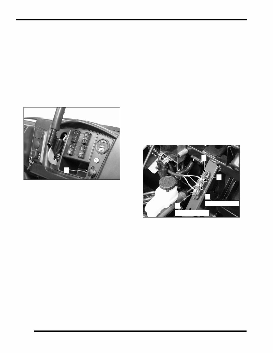
12 Volt Auxiliary Power Outlet
VOLTAGE LEVEL: 13.5 VDC
LOCATION: Dashboard
OVERVIEW: The 12-volt receptacle (A) is wired with the
accessory terminal board. The dash mounted receptacle and the
12 volt terminal board are on the same (10A ACCY) fuse in the
fuse box (10 amps total current capacity shared between
switched accessory power locations and constant power
terminal). Terminal A4 in fuse box is power to OR/WH ACCY
switched power wires leading to the terminal board and
receptacle.
SYSTEM WIRING DIAGRAM REFERENCE: See page 8.22.
Auxiliary 12 Volt Terminal Board / Sub-
Harness Power Supply Connection (EV-LSV)
VOLTAGE LEVEL: 13.5 VDC
LOCATION: Under hood on driver’s side.
OVERVIEW: The 12-volt terminal board (B) contains a
switched 12-volt supply (C), a ground terminal (D), and a
constant (non-switched) 12-volt supply (E).
The switched terminal (C) is limited to 10 amps (including loads
connected to the Auxiliary Power Outlet as described above).
The constant power terminal (E) is fused separately from the
switched power terminal (10 amp fuse in the main fuse box).
On LSV models, the sub-harness used for turn signals, hazard,
horn, and brake lights is connected to terminal D (ground) and
terminal E (constant power) of the terminal board. Electrical
loads on the sub-harness (up to approximately 2 amps) must be
considered when connecting loads to the un-switched terminal.
SYSTEM WIRING DIAGRAM REFERENCE:
Sub-Harness Wiring Diagram (page WD.7)
Sub-Harness Component and Splice Location (page WD.8)
Turn Signal / Hazard / Brake Light System Diagram
(page WD.9)
Horn System Diagram (page 8.36).
A
C
B
D
E
Sub-harness (+)
Sub-harness (-)
8.5
ELECTRICAL
8
© Copyright 2010 Polaris Sales Inc. 2011 POLARIS EV - LSV Service Manual 9923008
SWITCHES / CONTROLS
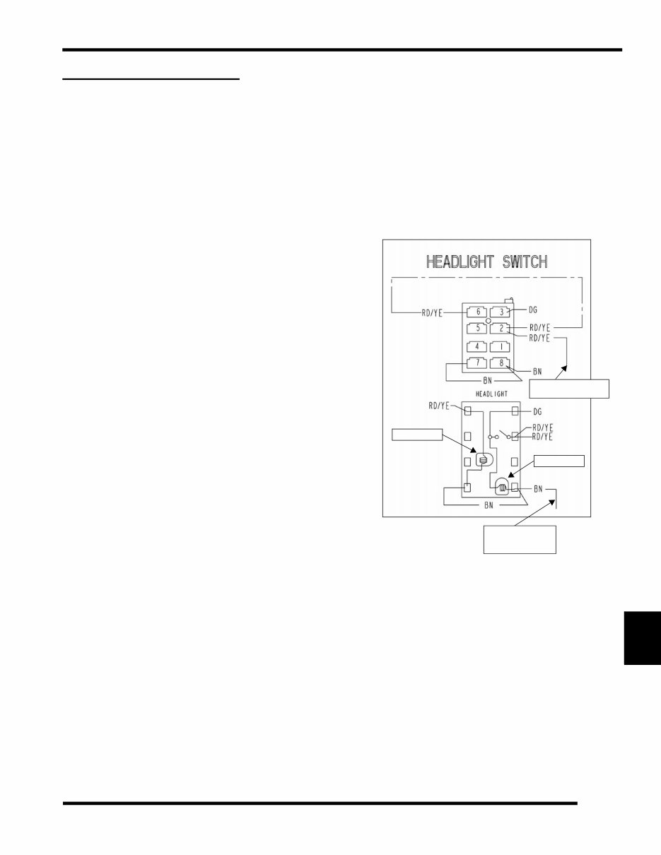
Headlight Switch
VOLTAGE LEVEL: 13.5 VDC
LOCATION: On Dashboard.
SYSTEM WIRING DIAGRAM REFERENCE: See page 8.23.
OVERVIEW: Headlight power is supplied to the headlight
switch via the RD/YE wire leading from the 10A LIGHTS fuse
(located in the fuse box under the hood), through Pin 10 of the
Chassis to Dash connector block. Power enters the headlight
switch on terminal 2.
When the headlight switch is in the OFF position, power
entering terminal 2 of the switch flows through the RD/YE
jumper wire to terminal 6, through the switch lamp to terminal
7 and 8, then to ground on the BN wire.
When the headlight switch is ON, power flows from terminal 2
to terminal 3 (DG), back through the Chassis / Dash connector
Pin 11 and on to the headlights. Note that in the ON position the
other switch lamp is powered and ground path is through
terminal 8 (BN).
If the headlight switch lamp is illuminated with the key switch
ON, power is reaching the switch through the fuse. If switch
lamp does not turn on with key switch, check the fuse. If fuse is
good (and powered), test for power on the RD/YE wire (terminal
2) of the switch harness. If power is present, test switch
continuity and ground path on the BN wires in the harness.
Headlight Switch Power and Ground Testing
NOTE: If switch is illuminated, this test is not required. The
ground is for switch lighting only.
1. Open hood. Reach under the dash and press tab on
headlight switch connector to disconnect wire harness
from switch. Do not pull on wiring.
2. Turn key switch ON.
3. Verify 12-14Vdc is present on the RD/YE wire.
4. Turn key switch OFF.
5. Verify ground path of BN wire(s) to the negative (-)
terminal on the controller with an Ohmmeter.
Headlight Switch Testing
1. Open hood. Reach under the dash and press tab on
headlight switch connector to disconnect wire harness
from switch. Do not pull on wiring.
2. Remove headlight switch from the dash.
3. Verify continuity exists between terminals 2 (RD/YE) and
terminal 3 (DG) when the switch is in the ON position.
• When the headlight switch is turned on, there should be
continuity between terminals 2 (Yellow) and 3 (Green).
IMPORTANT: Disconnect the Main Power Connector
(see chapter 1) before disconnecting any electrical
component. The Main Power Connector is the first to
disconnect and the last to connect when servicing the
electrical system.
From Pin 10 Chassis /
Dash connector
To chassis ground
splice (BN) in dash
Switch Lamp
Switch Lamp
harness
8.6
ELECTRICAL
© Copyright 2010 Polaris Sales Inc. 2011 POLARIS EV - LSV Service Manual 9923008
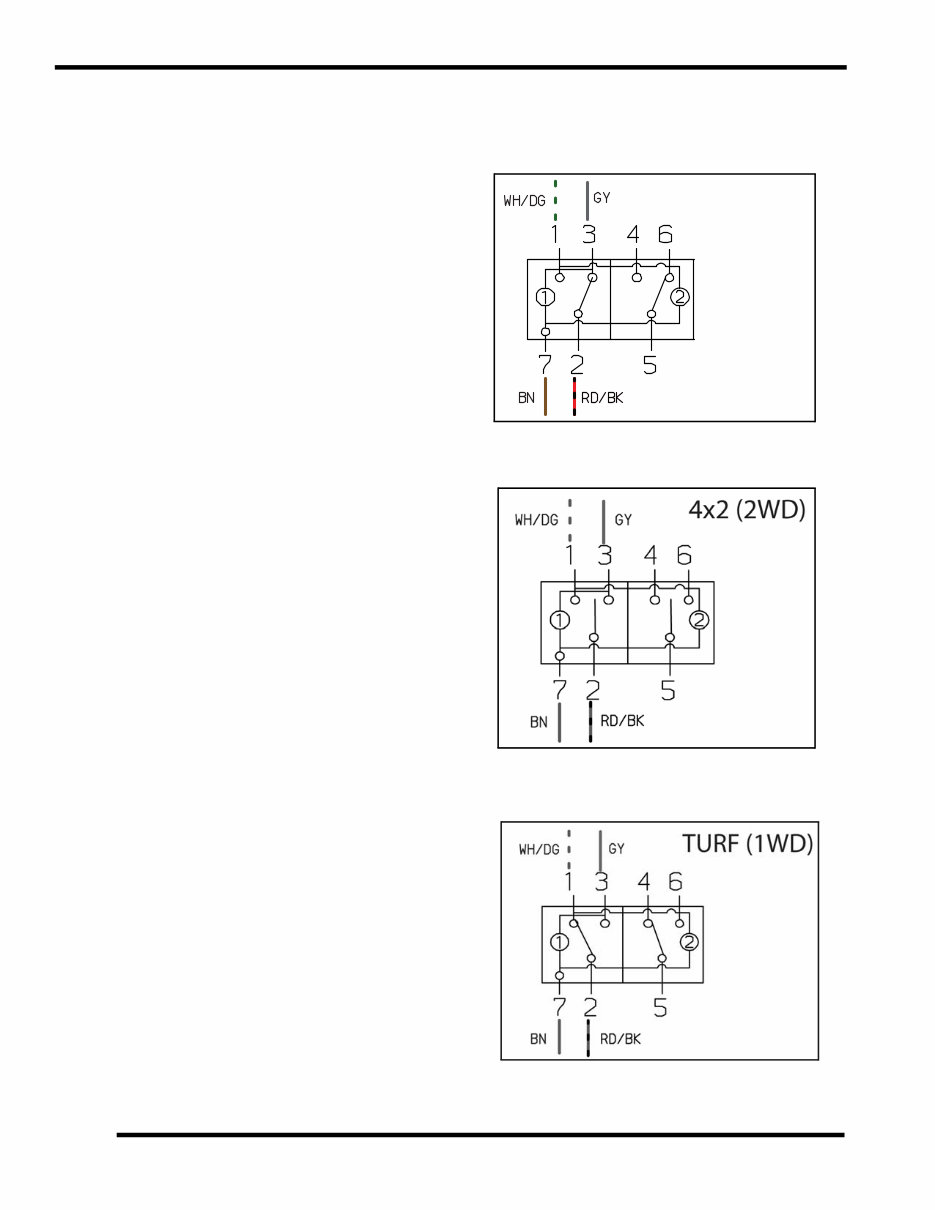
AWD / 2WD / TURF Switch
VOLTAGE LEVEL: 13.5 VDC
LOCATION: On Dashboard.
SYSTEM WIRING DIAGRAM REFERENCE: See page 8.25.
OVERVIEW: Power supply from terminal A8 of the fuse box
(RD/BK) is connected through Pin 9 of the Chassis to Dash
harness connector to terminal 2 of the AWD switch.
Power entering terminal 2 is switched as follows:
AWD (4x4): Power switched to terminal 3 (GY wire) is
connected through Pin 13 of the Chassis to Dash harness
connector to the AWD GY splice to the front hub coil connector
under the hood. If the BN/WH wire (to Pin 2 of the VCIM) is
connected to ground by the module, AWD is engaged.
2WD (4x2): No power flow through AWD switch.
TURF (1 WD): Power switched to terminal 1 (WH/GN wire) is
connected through Pin 12 of the Chassis to Dash harness
connector to Pin 7 of the VCIM. The VCIM then controls the
activation of the TURF solenoid driver on the dark green (DG)
wire to activate the differential solenoid and disengage the
differential hub.
AWD Switch Testing
1. Open hood. Reach under the dash and press tab on AWD
switch connector to disconnect wire harness from switch.
Do not pull on wiring.
2. Verify power is reaching the switch as described above.
3. Inspect switch connector pins and sockets and verify switch
continuity in the various positions. (See “AWD / 2WD /
Turf Switch Contacts” on page 8.26.)
IMPORTANT: Disconnect the Main Power Connector
(see chapter 1) before disconnecting any electrical
component. The Main Power Connector is the first to
disconnect and the last to connect when servicing the
electrical system.
4x4 (AWD)
SWITCH CONTACTS
8.7
ELECTRICAL
8
© Copyright 2010 Polaris Sales Inc. 2011 POLARIS EV - LSV Service Manual 9923008
Direction Selector Switch (F / N / R)
VOLTAGE LEVEL: 13.5 VDC
LOCATION: On Dashboard.
SYSTEM WIRING DIAGRAM REFERENCE: See page 8.27.
OVERVIEW: The direction selector switch completes a ground
connection to either the Forward (DB/RD), Neutral (DG/WH),
or Reverse (VT) circuit wires. The ground is sensed by the
controller to determine output to the drive motor.
The completed ground at the switch also turns on the appropriate
indicator light on the indicator light panel. (See “Direction
Selector - System Wiring Diagram” on page 8.27.)
Direction Selector Switch Testing
1. Open hood. Reach under the dash and press tab on switch
connector to disconnect wire harness from switch. Do not
pull on wiring.
2. Inspect switch connections and verify switch continuity in
the various positions as shown below or on page 8.28.
FORWARD
NEUTRAL
REVERSE
8.8
ELECTRICAL
© Copyright 2010 Polaris Sales Inc. 2011 POLARIS EV - LSV Service Manual 9923008
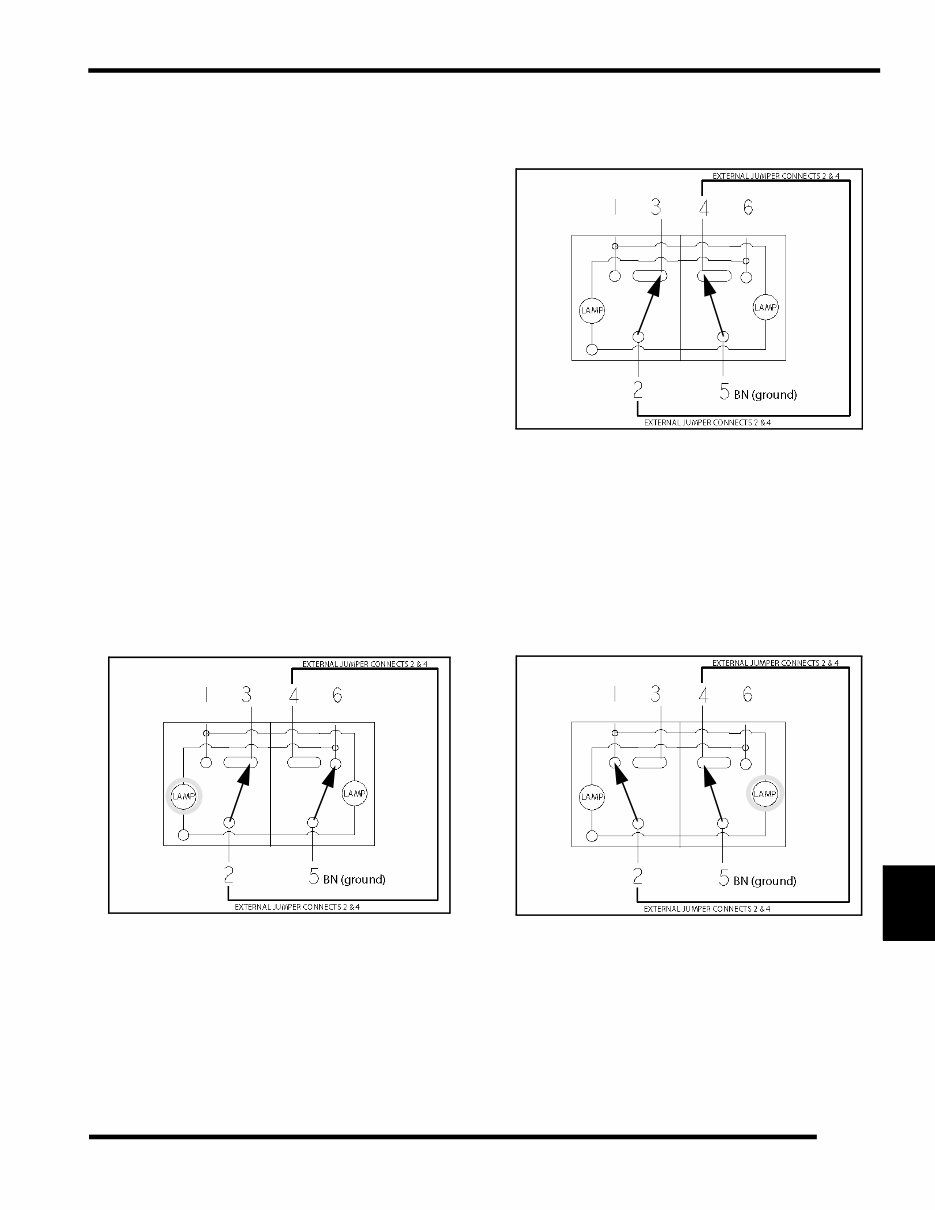
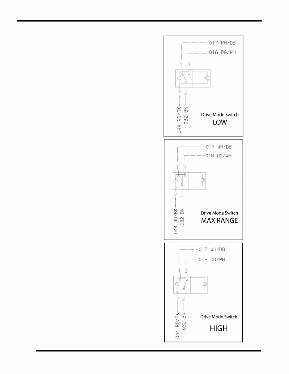
Drive Mode Switch (High, Max Range, Low)
VOLTAGE LEVEL: 13.5 VDC
LOCATION: On Dashboard.
SYSTEM WIRING DIAGRAM REFERENCE: See page 8.29.
OVERVIEW: The drive mode switch completes (or interrupts)
a ground connection to inform the controller which parameters
to follow when delivering power to the drive motor. The RD/BK
power wire at the switch is only used to power the switch lamps
(1 or 2) shown in the illustrations below.
LOW (L) - The switch connects the Low range wire (WH/DB)
to the ground wire (BN) through terminals 1 and 2 of the switch.
This completes the circuit connection back to Pin 20 at the
controller, and the controller follows Low range power delivery
parameters.
MAX RANGE (MAX) - The switch disconnects the Low range
(WH/DB) and the High range (DG/WH) wires from ground.
This interrupts the circuit connection back to Pin 20 and Pin 9
at the controller, and the controller follows MAX RANGE
power delivery parameters.
HIGH (H) - The switch connects the High range wire (DG/WH)
to the ground wire (BN) through terminals 3 and 2 of the switch.
This completes the circuit connection back to Pin 9 at the
controller, and the controller follows High range power delivery
parameters.
(See “Drive Mode (High / Max Range / Low) - System Wiring
Diagram” on page 8.29.)
Drive Mode Switch Testing
1. Open hood. Reach under the dash and press tab on switch
connector to disconnect wire harness from switch. Do not
pull on wiring.
2. Inspect switch connections and verify switch continuity in
the various positions as shown at right or on page 8.28.
8.9
ELECTRICAL
8
© Copyright 2010 Polaris Sales Inc. 2011 POLARIS EV - LSV Service Manual 9923008
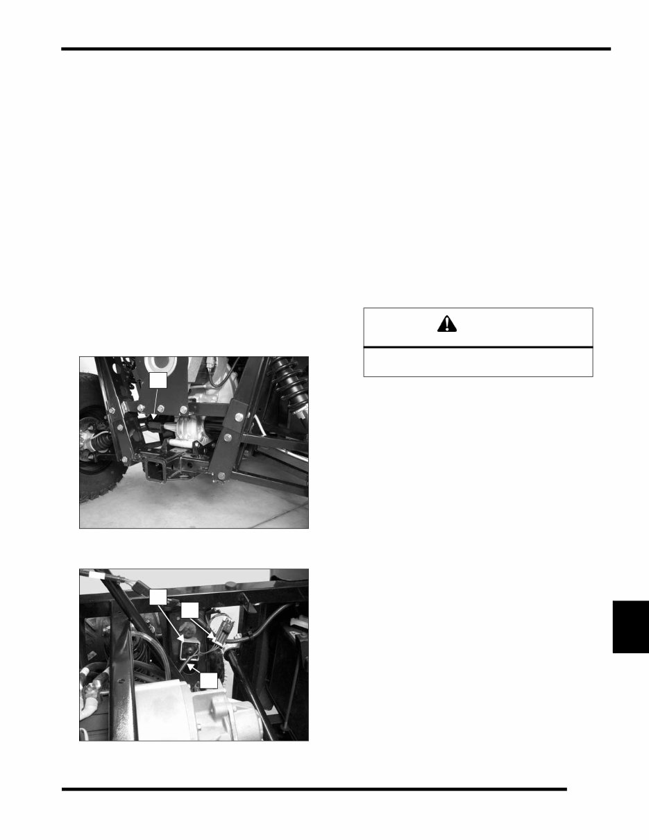
Differential Solenoid / Solenoid Driver
Module
VOLTAGE LEVEL: 13.5 VDC
LOCATION:
Solenoid (A): On differential housing of transaxle.
Driver Module (B): Under cargo box on LH (driver’s) side
frame. Input wire harness (to solenoid driver module) connector
is shown at (C), and output harness (to solenoid) at (D).
SYSTEM WIRING DIAGRAM REFERENCE: See page 8.25.
OVERVIEW: The differential solenoid driver is located on the
left side of the rear frame under the cargo box. When the
solenoid is energized by selecting TURF mode on the AWD
switch, the solenoid plunger extends and pushes against a shift
fork to disengage the differential dog gear with the differential.
NOTE: The rear differential will not unlock if the parking
brake is set.
SOLENOID TEST
The solenoid unit can be tested separately by briefly applying a
12 volt DC power source to the solenoid wires for no more than
1 second . Do not use the vehicle batteries for the test.
If the rear differential fails to switch from operational modes:
• Separate and inspect all solenoid and relay connectors.
• Check for power from the solenoid driver connector (to
ensure solenoid has power to be activated). Check
power supply to solenoid driver module.
• Check AWD switch and switch wire contacts.
• Remove solenoid and return spring from differential
case. Push lever arm manually to ensure mechanical
portion of system is functional. Test solenoid to be sure
the plunger is actuating.
IMPORTANT: Disconnect the Main Power Connector
(see chapter 1) before disconnecting any electrical
component. The Main Power Connector is the first to
disconnect and the last to connect when servicing the
electrical system.
A
B
D
C
CAUTION
Do not power the solenoid with 12 Volts for more
than 1 second, or damage may occur to solenoid.
8.10
ELECTRICAL
© Copyright 2010 Polaris Sales Inc. 2011 POLARIS EV - LSV Service Manual 9923008
Brake Light Switch (Hydraulic)
VOLTAGE LEVEL: 13.5 VDC
LOCATION: On master cylinder under the hood.
SYSTEM WIRING DIAGRAM REFERENCE: N/A
OVERVIEW: The hydraulic brake light switch contacts close
when brake pedal is applied, connecting the OR wire to ground.
Brake Light Switch Test
NOTE: Air in the hydraulic brake system could affect switch
operation. Be sure system is purged of all air and functioning
properly before testing the switch.
1. Disconnect wires from hydraulic brake switch.
2. Connect an ohmmeter across switch contacts. Reading
should be infinite (OL).
3. Apply foot brake. The switch contacts should have good
continuity (less than .5 Ohms).
4. Bleed hydraulic brake system if switch is replaced (see
Chapter 7).
Brake Light Switch Power Supply Test
1. Turn key switch ON. Be sure cargo box wire harness is
connected. Disconnect wires from hydraulic brake switch.
2. Connect an DC voltmeter to the OR (+) and BN (-) wires.
12-14 volts should be present.
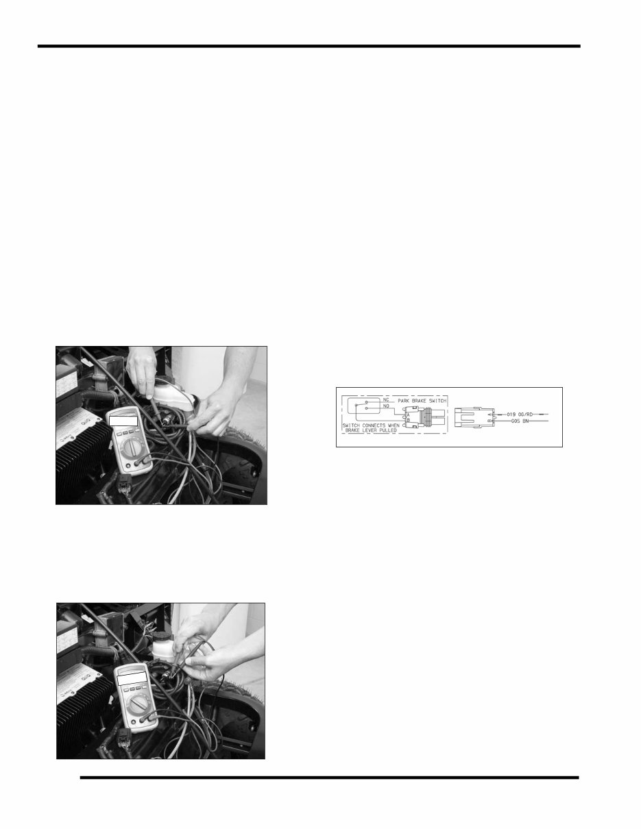
Parking Brake Switch
VOLTAGE LEVEL: 13.5 VDC
LOCATION: On park brake lever mechanism under the dash.
SYSTEM WIRING DIAGRAM REFERENCE: See page 8.24.
OVERVIEW: The switch is OPEN when park brake lever is not
applied. When parking brake is applied, switch contacts close,
connecting the OR/RD wire to ground, illuminating the park
brake lamp. The ground is also sensed by the Vehicle Control
Interface Module (VCIM) (to prevent differential solenoid
operation) and by the Controller to regulate drive motor output.
NOTE: If the parking brake is applied, the controller
will not send power to the drive motor, preventing
drive-away with the parking brake applied.
Parking Brake Switch Test
1. Release the parking brake lever (completely forward).
Disconnect wire harness from parking brake switch.
2. Connect an Ohmmeter to the switch terminals. Reading
should be infinite (OL).
3. Slowly apply parking brake while watching the meter.
Continuity should exist within 2-3 clicks from the brake
released position. If no continuity exists when parking
brake is applied, verify switch terminals and wire
connections are clean and tight. Replace switch if
necessary.
IMPORTANT: Disconnect the Main Power Connector
(see chapter 1) before disconnecting any electrical
component. The Main Power Connector is the first to
disconnect and the last to connect when servicing the
electrical system.
13.5vdc
You're Reading a Preview
What's Included?
Lifetime Access
Access Contents & Bookmarks
Print one or all pages of your manual