

2014-2015 Kawasaki Teryx 2 KRF800 UTV Service & Repair Manual
What's Included?
Fast Download Speeds
Online & Offline Access
Access PDF Contents & Bookmarks
Full Search Facility
Print one or all pages of your manual

TERYX
Recreation Utility Vehicle
Service Manual

This quick reference guide will assist
you in locating a desired topic or pro-
cedure.
•Bend the pages back to match the
black tab of the desired chapter num-
ber with the black tab on the edge at
each table of contents page.
•Refer to the sectional table of contents
for the exact pages to locate the spe-
cific topic required.
Quick Reference Guide
General Information 1
Periodic Maintenance 2
Fuel System (DFI) 3
Cooling System 4
Engine Top End 5
Converter System/Clutch 6
Engine Lubrication System 7
Engine Removal/Installation 8
Crankshaft/Transmission 9
Wheels/Tires 10
Final Drive 11
Brakes 12
Suspension 13
Steering 14
Frame 15
Electrical System 16
Appendix 17

LIST OF ABBREVIATIONS
A ampere(s) JASO Japanese Automotive Standards
Organization
ABDC after bottom dead center KACR Kawasaki automatic compression
release
AC alternating current KDS Kawasaki diagnostic system
Ah ampere hour km/h kilometers per hour
API American Petroleum Institute L liter(s)
ATDC after top dead center lb pound(s)
BBDC before bottom dead center LCD liquid crystal display
BDC bottom dead center LED light emitting diode
BTDC before top dead center m meter(s)
°C degree(s) celsius min minute(s)
cmHg centimeters of mercury mmHg millimeters of mercury
CPU central processing unit mph miles per hour
cu in. cubic inch(s) N newton(s)
CVT continuously variable transmission NLGI National Lubricating Grease Institute
DC direct current oz ounce(s)
DFI digital fuel injection Pa pascal(s)
DOT Department of Transportation PS horsepower
ECU electronic control unit psi pound(s) per square inch
EPS electric power steering qt quart(s)
F farad(s) r revolution
°F degree(s) fahrenheit rpm revolution(s) per minute
FET field effect transistor s second(s)
FI fuel injection SAE Society of Automotive Engineers
ft foot, feet TDC top dead center
g gram(s) TIR total indicator reading
gal gallon(s) V volt(s)
h hour(s) W watt(s)
HP horsepower(s) Ω ohm(s)
IC integrated circuit 2WD two wheel drive
in. inch(s) 4WD four wheel drive
ISC idle speed control
COUNTRY AND AREA CODES
CA Canada US United States

EMISSION CONTROL INFORMATION
To protect the environment in which we all live, Kawasaki has incorporated crankcase emis-
sion (1), exhaust emission (2), and evaporative emission (3) control systems in compliance with
applicable regulations of the United States Environmental Protection Agency.
1. Crankcase Emission Control System
A sealed-type crankcase emission control system is used to eliminate blow-by gases. The blow-by
gases are led to the breather chamber through the crankcase. Then, it is led to the air intake duct.
Oil is separated from the gases while passing through the inside of the breather chamber from the
crankcase, and then returned back to the bottom of crankcase.
2. Exhaust Emission Control System
The exhaust emission control system applied to this engine family is engine modifications that consist
of a catalytic converter in the muffler (US and CA models), a fuel injection and ignition system having
optimum ignition timing characteristics.
The fuel injection system has been calibrated to provide lean air/fuel mixture characteristics and opti-
mum fuel economy with a suitable air cleaner and exhaust system.
A maintenance free ignition system provides the most favorable ignition timing and helps maintain a
thorough combustion process within the engine which contributes to a reduction of exhaust pollutants
entering the atmosphere.
3. Evaporative Emission Control System
The evaporative emission control system for this vehicle consists of low permeation fuel hoses and a
fuel tank.
The Clean Air Act, which is the Federal law covering motor vehicle pollution, contains what is
commonly referred to as the Act’s "tampering provisions."
"Sec. 203(a) The following acts and the causing thereof are prohibited...
(3)(A) for any person to remove or render inoperative any device or element of design installed
on or in a motor vehicle or motor vehicle engine in compliance with regulations under this
title prior to its sale and delivery to the ultimate purchaser, or for any manufacturer or dealer
knowingly to remove or render inoperative any such device or element of design after such
sale and delivery to the ultimate purchaser.
(3)(B) for any person engaged in the business of repairing, servicing, selling, leasing, or trading
motor vehicles or motor vehicle engines, or who operates a fleet of motor vehicles know-
ingly to remove or render inoperative any device or element of design installed on or in a
motor vehicle or motor vehicle engine in compliance with regulations under this title follow-
ing its sale and delivery to the ultimate purchaser..."
NOTE
○ The phrase "remove or render inoperative any device or element of design" has been generally
interpreted as follows:
1. Tampering does not include the temporary removal or rendering inoperative of de-
vices or elements of design in order to perform maintenance.
2. Tampering could include:
a.Maladjustment of vehicle components such that the emission standards are ex-
ceeded.
b.Use of replacement parts or accessories which adversely affect the performance
or durability of the vehicle.
c.Addition of components or accessories that result in the vehicle exceeding the stan-
dards.

d.Permanently removing, disconnecting, or rendering inoperative any component or
element of design of the emission control systems.
WE RECOMMEND THAT ALL DEALERS OBSERVE THESE PROVISIONS OF FEDERAL LAW,
THE VIOLATION OF WHICH IS PUNISHABLE BY CIVIL PENALTIES NOT EXCEEDING
$10,000 PER VIOLATION.

PLEASE DO NOT TAMPER WITH NOISE CONTROL SYSTEM
(US MODEL only)
To minimize the noise emissions from this product, Kawasaki has equipped it with effective
inlet and exhaust silencing systems. They are designed to give optimum performance while
maintaining a low noise level. Please do not remove these systems, or alter them in any way
which results in an increase in noise level.
TAMPERING WITH EMISSION CONTROL SYSTEM PROHIBITED:
Federal regulations and California State law prohibit the following acts or the causing thereof:
(1) the removal or rendering inoperative by any person other than for purposes of maintenance,
repair, or replacement, of any device or element of design incorporated into any new vehicle for
the purposes of emission control prior to its sale or delivery to the ultimate purchaser or while it
is in use, or (2) the use of the vehicle after such device or element of design has been removed
or rendered inoperative by any person.
Do not tamper with the original emission related parts:
•
Throttle body and internal parts
•
Spark plugs
•
Alternator or electronic battery ignition system
•
Fuel filter/Fuel injector/Fuel pump
•
Air cleaner element
•
ECU (Electronic Control Unit)
Foreword
This manual is designed primarily for use by
trained mechanics in a properly equipped shop.
However, it contains enough detail and basic in-
formation to make it useful to the owner who de-
sires to perform his own basic maintenance and
repair work. A basic knowledge of mechanics,
the proper use of tools, and workshop proce-
dures must be understood in order to carry out
maintenance and repair satisfactorily. When-
ever the owner has insufficient experience or
doubts his ability to do the work, all adjust-
ments, maintenance, and repair should be car-
ried out only by qualified mechanics.
In order to perform the work efficiently and
to avoid costly mistakes, read the text, thor-
oughly familiarize yourself with the procedures
before starting work, and then do the work care-
fully in a clean area. Whenever special tools or
equipment are specified, do not use makeshift
tools or equipment. Precision measurements
can only be made if the proper instruments are
used, and the use of substitute tools may ad-
versely affect safe operation.
For the duration of the warranty period,
we recommend that all repairs and scheduled
maintenance be performed in accordance with
this service manual. Any owner maintenance or
repair procedure not performed in accordance
with this manual may void the warranty.
To get the longest life out of your vehicle:
•
Follow the Periodic Maintenance Chart in the
Service Manual.
•
Be alert for problems and non-scheduled
maintenance.
•
Use proper tools and genuine Kawasaki Vehi-
cle parts. Special tools, gauges, and testers
that are necessary when servicing Kawasaki
vehicles are introduced by the Service Man-
ual. Genuine parts provided as spare parts
are listed in the Parts Catalog.
•
Follow the procedures in this manual care-
fully. Don’t take shortcuts.
•
Remember to keep complete records of main-
tenance and repair with dates and any new
parts installed.
How to Use This Manual
In this manual, the product is divided into
its major systems and these systems make up
the manual’s chapters. The Quick Reference
Guide shows you all of the product’s system
and assists in locating their chapters. Each
chapter in turn has its own comprehensive Ta-
ble of Contents.
For example, if you want engine oil informa-
tion, use the Quick Reference Guide to locate
the Engine Lubrication System chapter. Then,
use the Table of Contents on the first page of
the chapter to find the Engine Oil section.
Whenever you see symbols, heed their in-
structions! Always follow safe operating and
maintenance practices.
DANGER
DANGER indicates a hazardous situa-
tion which, if not avoided, will result in
death or serious injury.
WARNING
WARNING indicates a hazardous situa-
tion which, if not avoided, could result
in death or serious injury.
NOTICE
NOTICE is used to address practices not
related to personal injury.
This manual contains four more symbols
which will help you distinguish different types
of information.
NOTE
○ NOTE indicates information that may help
or guide you in the operation or service of
the vehicle.
•
Indicates a procedural step or work to be
done.
○ Indicates a procedural sub-step or how to do
the work of the procedural step it follows. It
also precedes the text of a NOTE.
Indicates a conditional step or what action to
take based on the results of the test or inspec-
tion in the procedural step or sub-step it fol-
lows.
In most chapters an exploded view illustration
of the system components follows the Table of
Contents. In these illustrations you will find the
instructions indicating which parts require spec-
ified tightening torque, oil, grease or a locking
agent during assembly.

GENERAL INFORMATION 1-1
1
General Information
Table of Contents
Before Servicing ..................................................................................................................... 1-2
Model Identification................................................................................................................. 1-7
General Specifications............................................................................................................ 1-11
Unit Conversion Table ............................................................................................................ 1-15
1-2 GENERAL INFORMATION
Before Servicing
Before starting to perform an inspection service or carry out a disassembly and reassembly oper-
ation on a vehicle, read the precautions given below. To facilitate actual operations, notes, illustra-
tions, photographs, cautions, and detailed descriptions have been included in each chapter wherever
necessary. This section explains the items that require particular attention during the removal and
reinstallation or disassembly and reassembly of general parts.
Especially note the following:
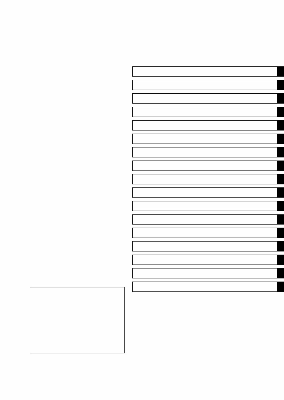
Battery Ground
Before completing any service on the vehicle, disconnect
the battery wires from the battery to prevent the engine from
accidentally turning over. Disconnect the ground wire (–)
first and then the positive (+). When completed with the
service, first connect the positive (+) wire to the positive
(+) terminal of the battery then the negative (–) wire to the
negative terminal.
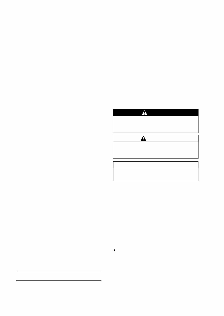
Edges of Parts
Lift large or heavy parts wearing gloves to prevent injury
from possible sharp edges on the parts.
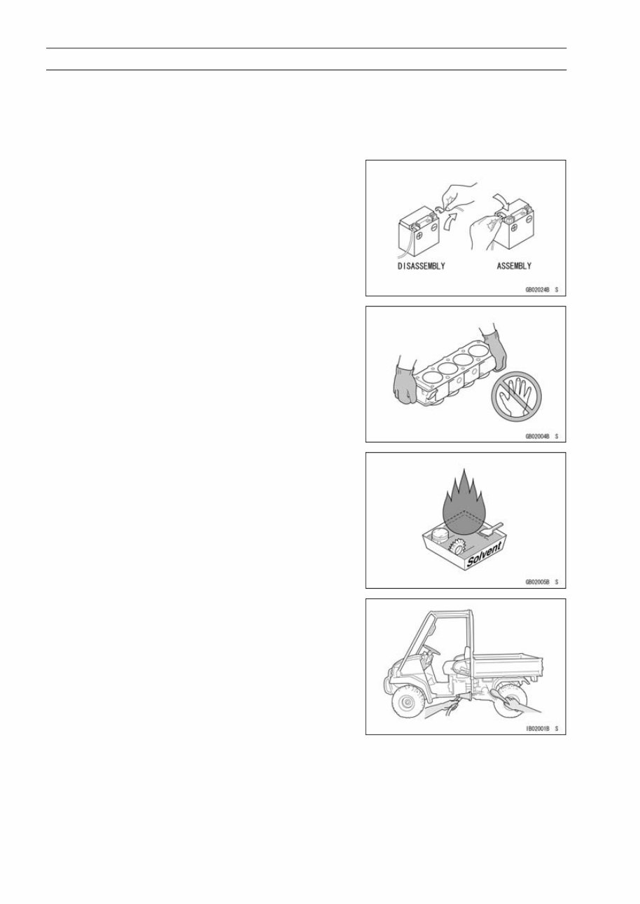
Solvent
Use a high flash-point solvent when cleaning parts. High
flash-point solvent should be used according to directions
of the solvent manufacturer.
Cleaning vehicle before disassembly
Clean the vehicle thoroughly before disassembly. Dirt or
other foreign materials entering into sealed areas during ve-
hicle disassembly can cause excessive wear and decrease
performance of the vehicle.
You're Reading a Preview
What's Included?
Fast Download Speeds
Online & Offline Access
Access PDF Contents & Bookmarks
Full Search Facility
Print one or all pages of your manual
$39.99
Viewed 25 Times Today


Secure transaction
What's Included?
Fast Download Speeds
Online & Offline Access
Access PDF Contents & Bookmarks
Full Search Facility
Print one or all pages of your manual
$39.99
- This Service & Repair Manual is a comprehensive factory workshop manual for the Kawasaki Teryx 2 KRF800 UTV for the years 2014-2015.
- It is designed for instant access on your computer, tablet, or smartphone, providing detailed repair, servicing, and troubleshooting procedures.
- The manual is a valuable resource for professional mechanics and DIY enthusiasts, featuring step-by-step instructions, detailed diagrams, and high-quality photos.
- Users have the flexibility to print out single pages or the entire manual as needed.
- It can be used on multiple computers without any limitations or trial periods, and there is no expiry date or renewal fee.
- Compatibility is ensured with both Windows and MAC computers.


