MTD Products Inc. - Product Training and Education Department FORM NUMBER - 769-01635 12/2004 4x2 Utility Vehicle Poly Bed and Steel Bed NOTE: These materials are prepared for use by trained technicians who are experienced in the service and repair of equipment of the kind described in this publication, and are not intended for use by untrained or inexperienced individuals. Such individuals should seek the assistance of an authorized service technician or dealer. Read, understand, and follow all directions when working on this equip- ment. This includes the contents of the Operators Manual, which came with your equipment. No liability can be accepted for any inac- curacies or omission in this publication, although every care has been take to make it as complete and accurate as possible. The right is reserved to make changes at any time to this document without prior notice and without incurring an obligation to make such changes to previously published documents. All information contained in this publication is based on product information available at the time of publication. Photographs and illustrations used in this publication are for reference use only and may not depict actual model and component parts. Service Manual K&T Saw Shop 606-678-9623 or 606-561-4983
K&T Saw Shop 606-678-9623 or 606-561-4983
Poly Bed 4 X 2 Drive System Customer Responsibilities ............................................................................................ 1 Gear Lube ..................................................................................................................... 1 Diagnosis: Confirming Transaxle Fault ......................................................................... 3 Transmission Linkages ................................................................................................. 3 Diagnosis and Service: Drive Belt and Clutches (CVT or Continuously Variable Transmission) ................................................... 11 Transaxle Removal and Replacement ........................................................................ 20 Transaxle Installation Notes: ....................................................................................... 24 Link Assembly ............................................................................................................. 25 Transaxle Repairs ....................................................................................................... 26 Poly Bed 4 X 2 Brake System Maintnance and Description of the Brake System ...................................................... 39 Complete Inspection (Drum and Shoe Removal) ...................................................... 40 Brake Adjustment (under the hood) 43 4 X 2 Drive System - (Steel Bed) Customer Responsibilities .......................................................................................... 47 Gear Lube ................................................................................................................... 47 Diagnosis: Confirming Transaxle Fault ....................................................................... 48 Diagnosis and Service: Drive Belt and Clutches (CVTor Continuously Variable Transmission) ...................................................... 49 CVT Removal: Driven Pulley ...................................................................................... 52 CVT Removal: Driving Pulley ...................................................................................... 53 Transaxle Removal and Replacement ........................................................................ 55 Transaxle Installation Notes: ....................................................................................... 59 Link Assembly ............................................................................................................. 60 Transaxle Orientation .................................................................................................. 61 Transaxle Disassembly: Axle tube Removal and Case Separation ............................ 62 Transaxle Disassembly: Gear Set Removal and Disassembly ................................... 64 Transaxle Disassembly: Differential ............................................................................ 68 Transaxle: Axle Tubes ................................................................................................ 70 In-cradle Engine Service ............................................................................................. 74 TABLE OF CONTENTS K&T Saw Shop 606-678-9623 or 606-561-4983
K&T Saw Shop 606-678-9623 or 606-561-4983
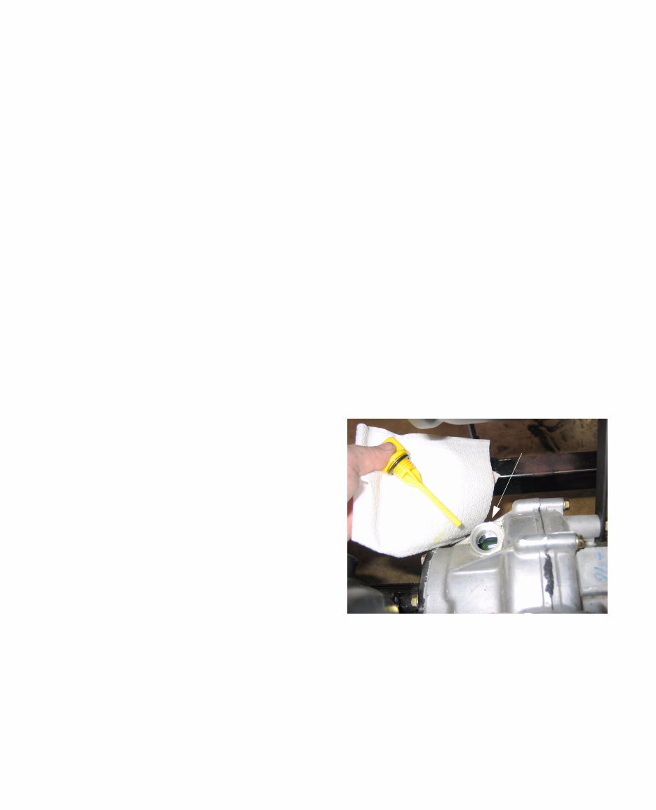
Poly Bed 4 X 2 Drive System 1 ABOUT THIS SECTION: This section covers the drive system and transaxle used in the Big Country utility vehicle model series 414 (37AN414J710). This model is distinguished from the 420 and 430 series by a polymer bed and the use of a different drive system. The 420 and 430 series use a Honda 18 hp. V-twin engine and a Dana transaxle. The 414 uses a drive system manufactured by Kawasaki. 1. CUSTOMER RESPONSIBILITIES • Housing, axle, bearing, or axle tube damage caused by impact or over-loading constitutes customer abuse, and is not covered under the warranty. The poly bed Big Country has a lower load rating than the steel bed version: 900 Lb. (410 KG) including bed load, operator, and pas- senger. • Damaged caused by shock-loading the trans- mission is not covered under the warranty. Shock-loading is primarily caused by shifting between forward and reverse gears without allowing the vehicle to come to a full stop. This is possible if the vehicle is operated abusively • Damage caused by a lubrication failure is not covered under the warranty. • It is the customer’s responsibility to have any leaks repaired in a timely fashion. • The lug nuts should be inspected for looseness after the first ten hours of operation. Lug nuts should be tightened to a torque of 55-60 ft.-lbs. • The brakes are not self-adjusting. It is the cus- tomer’s responsibility to maintain them in good working order and proper adjustment, whether directly or through an authorized Cub Cadet Ser- vicing Dealer. • It is the customer’s responsibility to maintain the vehicle in accordance with the Operator’s Man- ual. This includes an initial gear lube change after 50 hours of operation, and changes every 500 hours of operation (or 2 years) thereafter. • The gear lube level should be checked every 100 hours of operation. At this time a visual inspection should be made for leaks or damage. 2. GEAR LUBE 2.1. Service intervals: Initial change: 50 hours Subsequent changes: 500 hours of 2 years Check level: every 100 hours. 2.2. The transaxle should contain 68 fluid ounces (2.0 L) API “GL-5” hypoid gear lube. • SAE 90 weight above 41deg. f. (5 deg. C.) • SAE 80 weight below 41 deg. f. (5 deg. C.) 2.3. To check the gear lube level, park the vehicle on a flat level surface. 2.4. Clean the area around the oil fill cap/dipstick near the back of the transaxle housing and remove the dipstick. 2.5. Wipe the dipstick clean, insert it back into the threaded hole, but do not thread it in. 2.6. Withdraw the dipstick and check the oil level. It should be between the upper and lower level lines. The area between the lines is marked with cross-hatch. See Figure 2.6. 2.7. If additional lube is needed, confirm the current contents of the transaxle, and add more of the same to reach the specified level. 2.8. If additional fluid is needed, inspect the transaxle for leaks or damage. If leakage is found, make any necessary repairs before returning the vehi- cle to service. Figure 2.6 Dipstick location Poly Bed 4 X 2 Drive System K&T Saw Shop 606-678-9623 or 606-561-4983
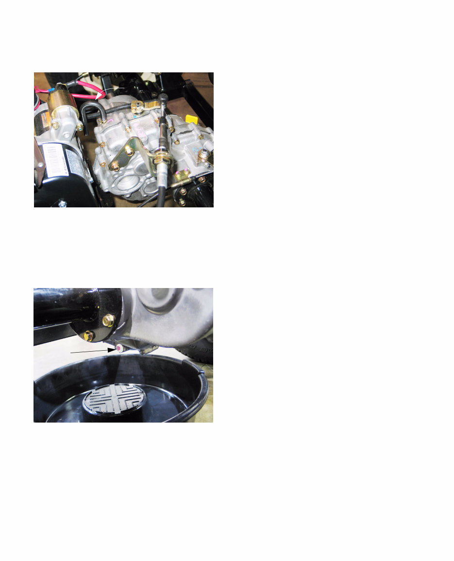
Poly Bed 4 X 2 Drive System 2 2.9. A blocked vent can provoke oil leaks. The vent is located at the top of the transaxle housing. See Figure 2.9. 2.10. To change the gear lube: Clean the area around the fill and drain plugs before removing either. 2.11. Place a drain pan under the transaxle. See Figure 2.11. 2.12. Remove the drain plug at the lower left corner of the transaxle using a 12mm wrench. NOTE: 80 and 90 weight gear lubes are very thick at low temperatures, and may take consid- erable time to drain if the ambient temperature is below 41 deg. f. (5 deg. C.) 2.13. Remove the oil fill cap/dipstick. This will allow air to enter the transaxle faster, which will allow the gear lube to drain faster. 2.14. Install the drain plug and tighten it to a torque of 132 in.-lb. (15 N-m). 2.15. Add 68 fluid ounces (2.0 L) API “GL-5” hypoid gear lube, and install the oil fill cap/dipstick. • SAE 90 weight above 41deg. f. (5 deg. C.) • SAE 80 weight below 41 deg. f. (5 deg. C.) 2.16. Confirm the correct fluid level by by inserting (but not threading-in) the fill cap/dipstick, and withdrawing it to read the level. Figure 2.9 Vent line Figure 2.11 Drain plug K&T Saw Shop 606-678-9623 or 606-561-4983
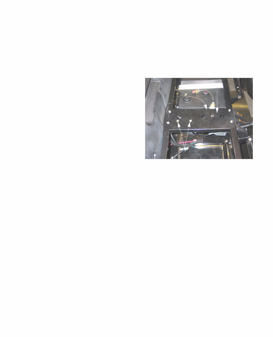
Poly Bed 4 X 2 Drive System 3 3. DIAGNOSIS: CONFIRMING TRANSAXLE FAULT 3.1. Get as much information as possible from the customer regarding symptoms and circum- stances. 3.1. Inspect the vehicle for physical damage and clues regarding the nature and cause of failure. 3.2. Carefully operate the vehicle if possible, to con- firm noises and symptoms. 3.3. Confirm whether the problem is internal, in the shift linkage, brake system, or the belt drive sys- tem (CVT): • If a drive gear (forward or reverse) or the differ- ential lock fail to engage or disengage by manu- ally overriding the shift mechanism. • Shift mechanism issues can be isolated from internal issues by disconnecting the cables at the transaxle end, and operating the transaxle directly. • Performance problems such as failure to reach full speed are likely to be caused by engine, brake, or belt/clutch issues. • Complaints of “lurchy” operation are an indica- tion that the brakes may be dragging or adjusted too tight. • It is easy to check for dragging brakes by push- ing the vehicle with the parking brake released, or by jacking-up the back of the vehicle and checking the wheels for ease-of rotation. • Refer to the “Brake” section of this manual for service and adjustment information. • Gear clash can result from drive being applied to the input shaft during shifting. Refer to the “CVT” section of this manual for performance information. • Gear “spit-out” or gear clash when the gear selector is in Neutral can result from a mis- adjusted shift linkage. Refer to the “Transmis- sion Linkage” section of this manual. • Under-steer (vehicle is less responsive to steer- ing wheel in-puts) accompanied by rear wheel squeal during turning maneuvers indicates that the differential lock is engaged. If this condition exists when the differential lock lever is released, refer to the “Transmission Linkages” section of this manual. 4. TRANSMISSION LINKAGES Shift Control Cable 4.1. It is possible to remove the gear shift control cable and gear shift control independently or together. 4.2. To gain access to the gear shift control, tilt both seats forward, and remove the console/cup holder using a 7/16” wrench. See Figure 4.2. 4.3. Unbolt the console support plate from the frame using a 7/16” wrench. NOTE: The vacuum driven fuel pump is mounted to the bottom of the console support plate. It may be unbolted from the plate using a pair of 7/16” wrenches so that the plate may be completely removed. It is not absolutely neces- sary to unbolt the fuel pump if the support plate is only moved aside for access. 4.4. Un-hook the differential lock return spring from the console support plate, and move (or remove) the plate. Figure 4.2 Console support plate Fuel pump mounting bolts Differential lock return spring K&T Saw Shop 606-678-9623 or 606-561-4983
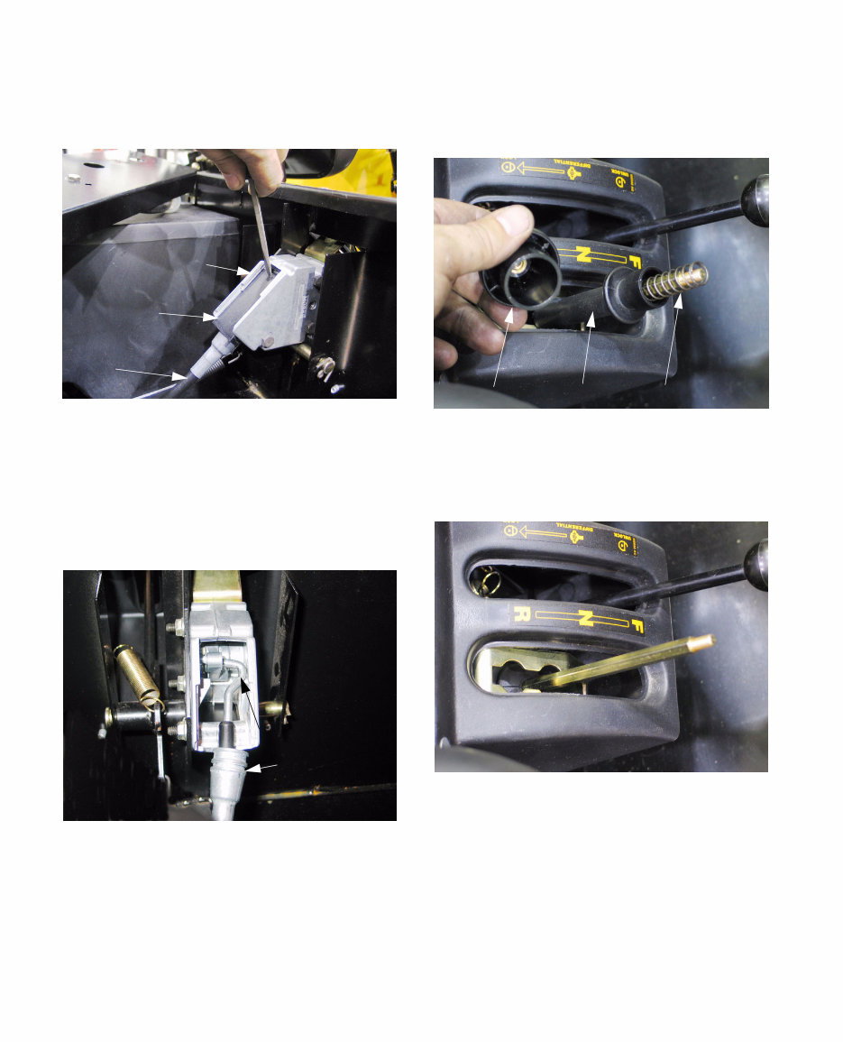
Poly Bed 4 X 2 Drive System 4 4.5. There is a black plastic cover on the gearshift control. Slide it rearward, then lift it away from the gear shift control to expose the cable attach- ment. See Figure 4.5. NOTE: There is a lip at the front edge of the cover that will provide sufficient purchase to slide the cover back. 4.6. With the cover removed, lift the shift control cable housing end out of the recess that locates it in the shift control housing. See Figure 4.6. 4.7. Disengage the hooked end of the cable from the shift control and lift the cable out of the shift con- trol housing. Shift Control 4.8. If the shift control is to be removed, the knob must be taken-off the shift lever. It threads off. See Figure 4.8. 4.9. The knob retains a spring and a lock collar. Both can be removed after the knob is taken off. See Figure 4.9. 4.10. Three nuts and bolts secure the shifter control to the frame. The nuts may be removed with a pair of 7/16” wrenches. The shifter control may then be removed. 4.11. There are no internal replacement parts avail- able through Cub Cadet for the shifter control. It is to be replaced as an assembly. Figure 4.5 Gear shift cable Plastic cover Gear shift control Figure 4.6 Cable housing end Hook Figure 4.8 Knob Lock collar Spring Figure 4.9 K&T Saw Shop 606-678-9623 or 606-561-4983
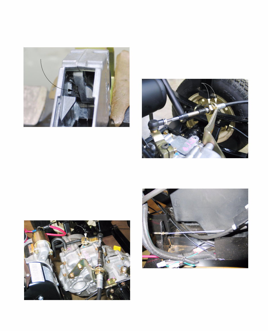
Poly Bed 4 X 2 Drive System 5 4.12. Within the housing for the shifter control there is a torsion spring that returns the shift lever to the center of its travel. There is not a detent mech- anism in the shifter control. See Figure 4.12. 4.13. On installation of the shifter control: • Position the bolts in the shifter control housing prior to installation. There is insufficient lateral clearance to instal them all in-situ. • Tighten the nut to 96 in-lb. (10.848 Nm). If the nuts are too tight, the housing will distort, and operating effort will increase. 4.14. If the cable is to be replaced, the front end of the cable can be disconnected as described in the procedure for removal of the shifter control. 4.15. The back end of the cable is permanently attached to the shifter arm. See Figure 4.15. Figure 4.12 Return spring Figure 4.15 Index mark Clamp bolt 4.16. Match-mark the shifter arm to the splined end of the shift arm shaft, then remove the clamp bolt using a 10 mm wrench. NOTE: The clamp bolt engages a groove in the shift shaft. It must be removed. 4.17. Use a pair of 7/8” wrenches to remove the end jam nut on the threaded end of the cable hous- ing. The cable core will pass through a slot in the bracket. See Figure 4.17. 4.18. The cable can be withdrawn from the vehicle in either direction. See Figure 4.18. NOTE: The correct routing of the cable: through the recess in the lower front corner of the tank. 4.19. Confirm that the cable is correctly adjusted before returning the vehicle to service. Figure 4.17 Jam nuts Figure 4.18 Note cable routing K&T Saw Shop 606-678-9623 or 606-561-4983
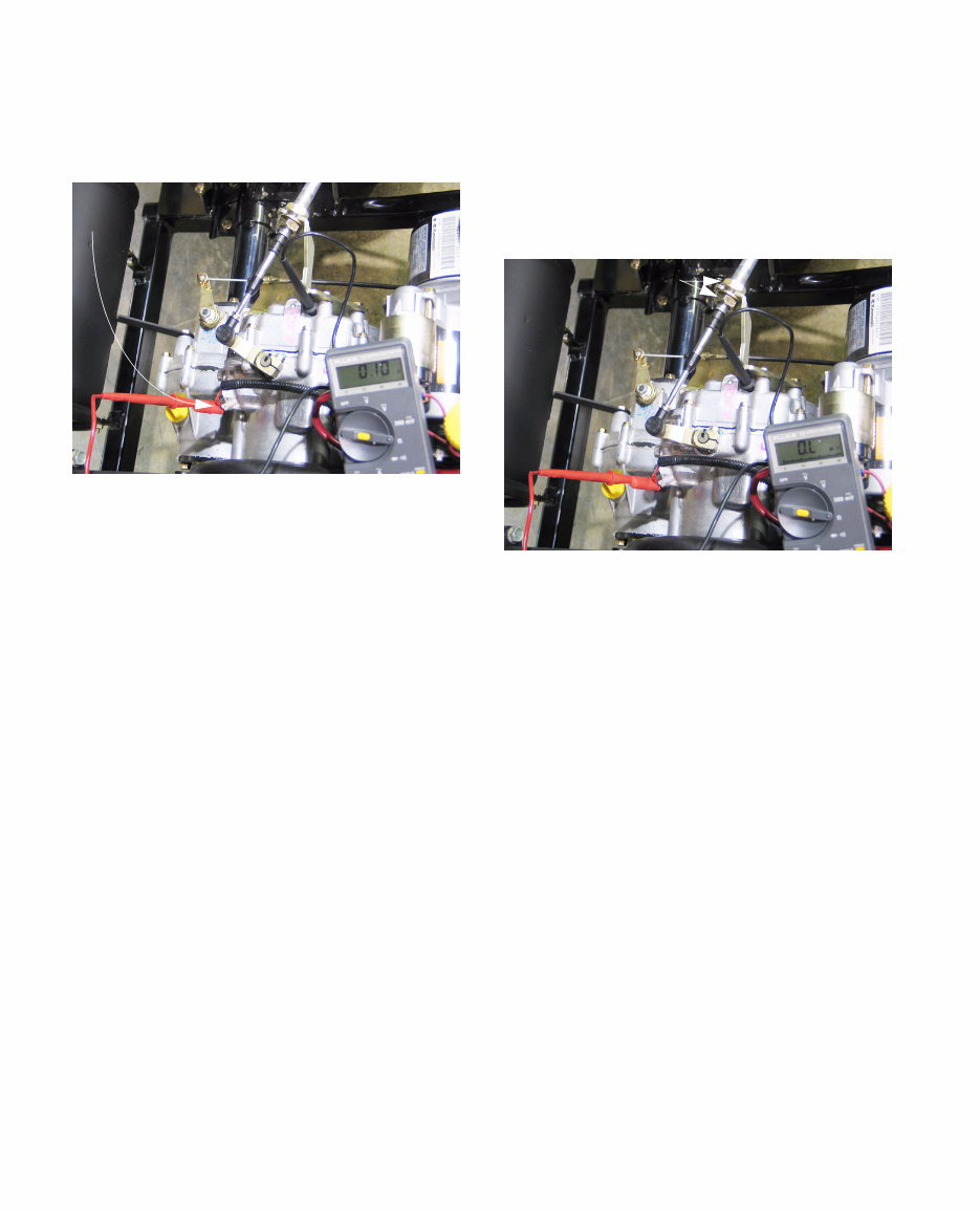
Poly Bed 4 X 2 Drive System 6 Shift Control Adjustment 4.20. To adjust the shift cable, use the neutral safety switch to confirm the neutral position. See Figure 4.20. • Connect a powered continuity light or an Ohm meter between the terminal on the neutral switch and a good ground. This test works key-off. • Otherwise, connect a test light in series between the terminal on the neutral switch and the eyelet on the wire that attaches to it. This test works key-on, engine-off. • When the continuity or test light bulb illuminates, or the Ohm meter registers zero, the contacts within the switch are closed. • When the neutral switch is closed, the transmis- sion is in neutral. Move the shifter through its range of travel to confirm that the switch is work- ing correctly. • There is a significant range of travel around the neutral position before the contacts in the neutral switch open. 4.21. With the transmission confirmed to be in neutral by the meter or light connected to the switch, move the gearshift lever to the neutral position. 4.22. Adjust the jam nuts as necessary so that the contacts in the neutral switch open when the gearshift lever is moved an equal distance in the direction of forward and reverse gear positions. See Figure 4.22. 4.23. Tighten the jam nuts and test the operation of the shift control before returning the unit to ser- vice. 4.24. Inspect the cable for wear or damage. Replace it if there are any signs of fraying, binding, kink- ing or damage to the cable housing. 4.25. Lubricate the cable with light oil (penetrating oil or cable lube) any time it is removed, and at 500 hr. intervals when the gear lube is changed. 4.26. Depending on the type of service being done, the gear shift control cable may be removed from it sprocket on the transaxle, or the bracket may be removed from the transaxle housing using a 10 mm wrench. 4.27. On installation, the gear shift control bracket should be tightened to a torque of 78 in-lb. (8.8 N-m). Figure 4.20 Use safety switch to find neutral Figure 4.22 Adjust cable here K&T Saw Shop 606-678-9623 or 606-561-4983
You're Reading a Preview
What's Included?
Lifetime Access
Fast Download Speeds
Online & Offline Access
Access PDF Contents & Bookmarks
Full Search Facility
Print one or all pages of your manual
$31.99
Cub Cadet 4x2 Utility Vehicle Poly Bed Steel Bed Service Repair Workshop Manual
The Cub Cadet 4x2 Utility Vehicle Poly Bed Steel Bed Service Repair Manual is a comprehensive resource suitable for both professional mechanics and DIY enthusiasts. It contains easy-to-read text sections, high-quality diagrams, and clear instructions, making it an invaluable tool for servicing the poly bed 4x2 drive system and brake system of the vehicle.
The manual covers a wide range of topics including customer responsibilities, gear lube, diagnosis of transaxle faults, transmission linkages, drive belt and clutches service, transaxle removal and replacement, brake system maintenance and inspection, brake adjustment, CVT removal, transaxle disassembly, and in-cradle engine service.
File Format: PDF
Compatibility: All Versions of Windows & Mac
Language: English
Requirements: Adobe Reader
With the Cub Cadet 4x2 Utility Vehicle Poly Bed Steel Bed Service Repair Manual, you can save time and money by performing maintenance and repairs yourself, with the confidence that comes from having access to detailed and accurate information. This manual is an essential resource for anyone looking to effectively service their Cub Cadet 4x2 Utility Vehicle Poly Bed Steel Bed.
Reviews
Q&A
Recently Viewed
5,521,897Happy Clients
2,594,462eManuals
1,120,453Trusted Sellers
15Years in Business
Price:
Actual Price:
Cub Cadet 4x2 Utility Vehicle Poly Bed Steel Bed Service Repair Workshop Manual






 Lifetime Access




