

® @
ICHAsld' -------
®
ISPECI rr I I OPT I 0 I
@~@~
@~ ®~
1
m
1
B
1.
a
@
__8*\
OE031
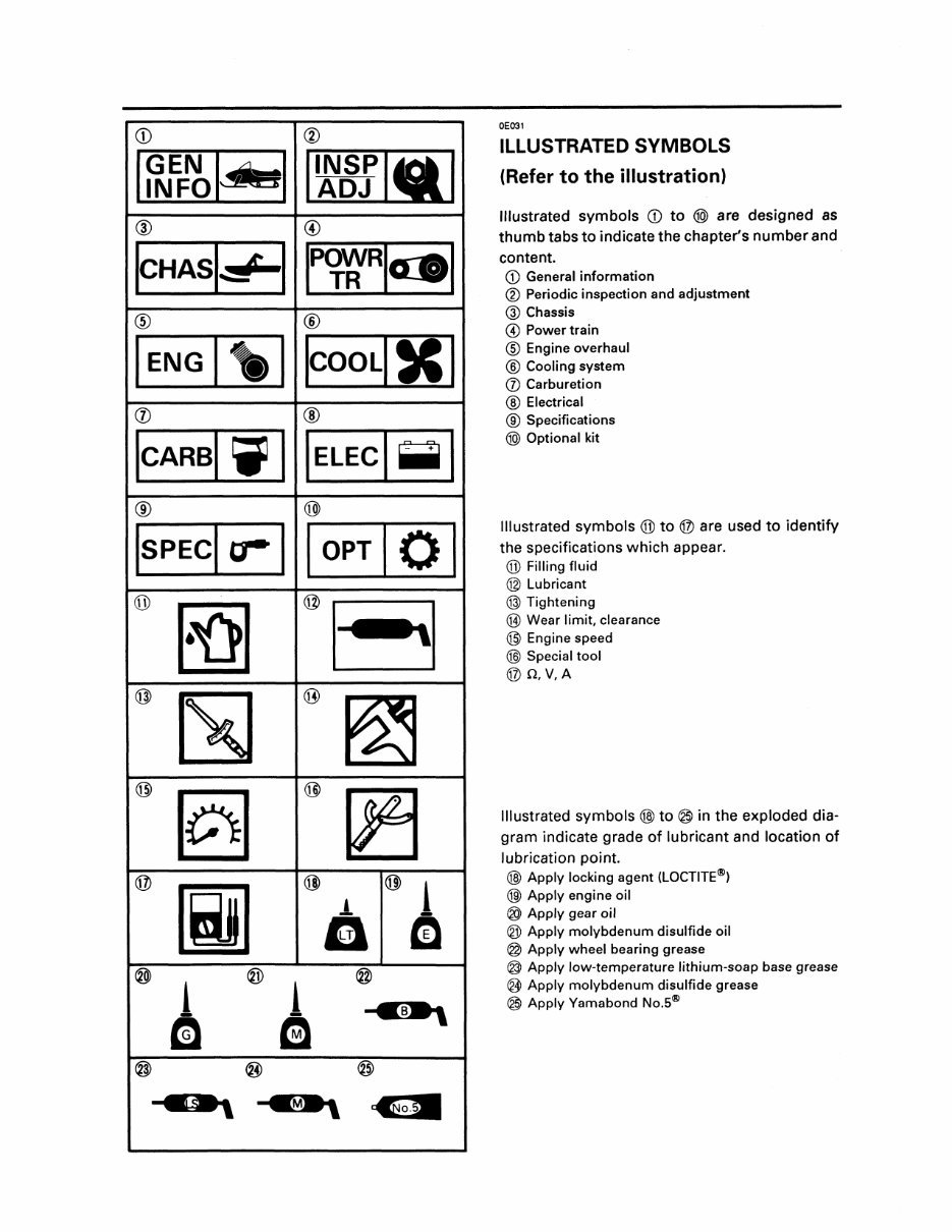
ILLUSTRATED SYMBOLS
(Refer to the illustration)
Illustrated symbols CD to @> are designed as
thumb tabs to indicate the chapter's number and
content.
CD General information
® Periodic inspection and adjustment
@ Chassis
@ Power train
® Engine overhaul
® Cooling system
en Carburetion
® Electrical
® Specifications
@> Optional kit
Illustrated symbols ® to ® are used to identify
the specifications which appear.
® Filling fluid
@ Lubricant
@ Tightening
® Wear limit, clearance
@ Engine speed
@) Special tool
®n,V,A
Illustrated symbols @) to @ in the exploded dia-
gram indicate grade of lubricant and location of
lubrication point.
@) Apply locking agent (LOCTITE®)
@) Apply engine oil
@ Apply gear oil
@ Apply molybdenum disulfide oil
@ Apply wheel bearing grease
@ Apply low-temperature lithium-soap base grease
@ Apply molybdenum disulfide grease
@ Apply Yamabond No.5®
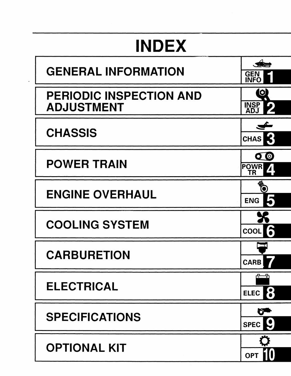
INDEX
GENERAL INFORMATION
PERIODIC INSPECTION AND
ADJUSTMENT
CHASSIS
POWER TRAIN
ENGINE OVERHAUL
COOLING SYSTEM
CARBURETION
ELECTRICAL
SPECIFICATIONS
OPTIONAL KIT
CHAS
SPEC
OPT
_____________________________ ~~~ldiul
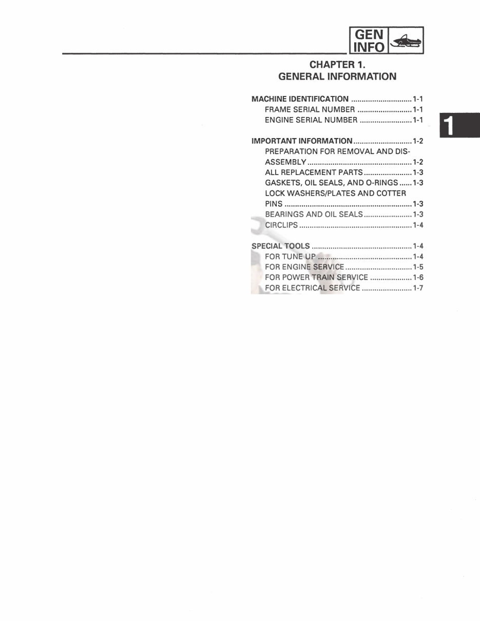
CHAPTER 1.
GENERAL INFORMATION
MACHINE IDENTIFICATION ............. .. .............. 1-1
FRAME SERIAL NUMBER ... ....................... 1-1
ENGINE SERIAL NUMBER .................... .. ... 1-1
IMPORTANT INFORMATION ................• ........... 1-2
PREPARATION FOR REMOVAL AND DIS-
ASSEMBLY .................................................. 1-2
ALL REPLACEMENT PARTS ....................... 1-3
GASKETS, OIL SEALS, AND O-RINGS ...... 1-3
LOCK WASHERS/PLATES AND COTTER
PINS ....................................................... .. .... 1-3
BEARINGS AND OIL SEALS ....................... 1-3
CIRCLIPS ...................................................... 1-4
SPECIAL TOOLS ................................................ 1-4
FOR TUNE UP ............................................. 1-4
FOR ENGINE SERVICE ................................ 1-5
FOR POWER TRAI N SERVICE .................... 1-6
FOR ELECTRICAL SERVICE ........................ 1-7
MACHINE IDENTIFICATION II~~~ l-:As I
1-1
lEOOl
GENERAL
INFORMATION
MACHINE IDENTIFICATION
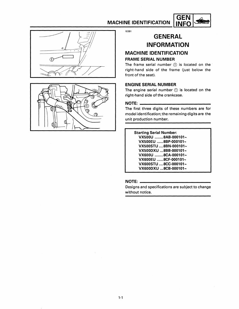
FRAME SERIAL NUMBER
The frame serial number CD is located on the·
right-hand side of the frame (just below the
front of the seat).
ENGINE SERIAL NUMBER
The engine serial number CD is located on the
right-hand side of the crankcase.
NOTE: ______________________ _
The first three digits of these numbers are for
model identification; the remaining digits are the
unit production number.
Starting Serial Number:
VX500U ......•. SAB-0001 01 ..
VX500EU ..•... SBp·000101 ..
VX500STU .... SBN·000101 ..
VX500DXU ... SBB·000101 ..
VX600U ........ 8CA·0001 01 ..
VX600EU ...... SCF·000101 ..
VX600STU .... SCC·000101 ..
VX600DXU ... SCB·000101 ..
NOTE: ______________________ ___
Designs and specifications are subject to change
without notice.
IMPORTANT INFORMATION 1 ~~~ 1 ...... 1
1-2
lEOll
IMPORTANT INFORMATION
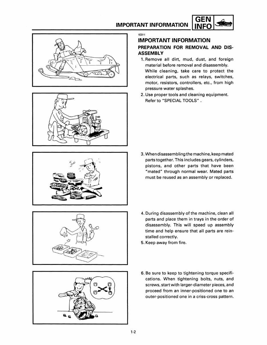
PREPARATION FOR REMOVAL AND DIS-
ASSEMBLY
1. Remove all dirt, mud, dust, and foreign
material before removal and disassembly.
While cleaning, take care to protect the
electrical parts, such as relays, switches,
motor, resistors, controllers, etc., from high
pressure water splashes.
2. Use proper tools and cleaning equipment.
Refer to "SPECIAL TOOLS" .
3. When disassembling the machine, keep mated
parts together. This includes gears, cylinders,
pistons, and other parts that have been
"mated" through normal wear. Mated parts
must be reused as an assembly or replaced.
4. During disassembly ofthe machine, clean all
parts and place them in trays in the order of
disassembly. This will speed up assembly
time and help ensure that all parts are rein-
stalled correctly.
5. Keep away from fire.
6. Be sure to keep to tightening torque specifi-
cations. When tightening bolts, nuts, and
screws, start with larger-diameter pieces, and
proceed from an inner-positioned one to an
outer-positioned one in a criss-cross pattern.
IMPORTANT INFORMATION 1 ~~~ 1.1L I
300-000
300-002
300-003
'-3
ALL REPLACEMENT PARTS
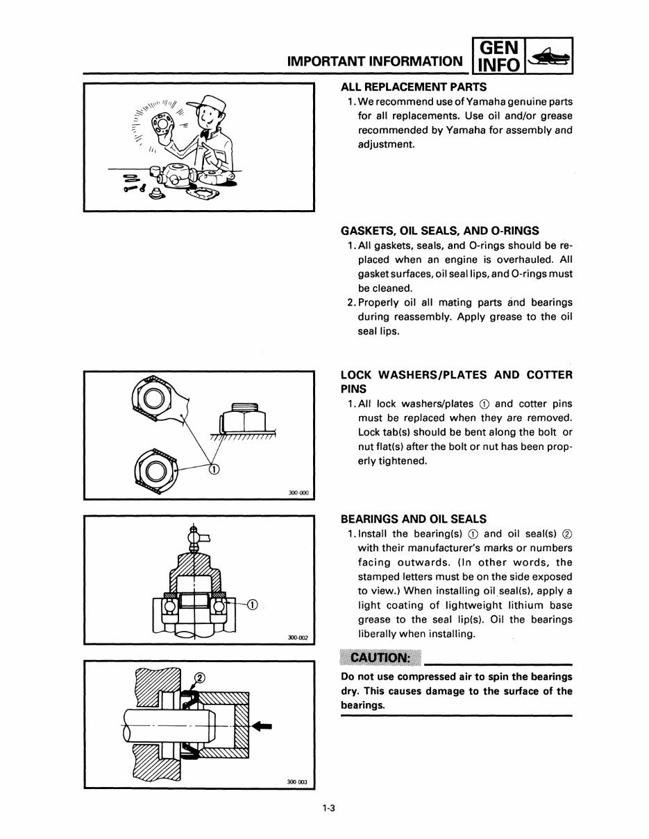
1. We recommend use of Yamaha genuine parts
for all replacements. Use oil and/or grease
recommended by Yamaha for assembly and
adjustment.
GASKETS, OIL SEALS, AND O-RINGS
1. All gaskets, seals, and O-rings should be re-
placed when an engine is overhauled. All
gasket surfaces, oil seal lips, and O-rings must
be cleaned.
2. Properly oil all mating parts and bearings
during reassembly. Apply grease to the oil
seal lips.
LOCK WASHERS/PLATES AND COTTER
PINS
1. All lock washers/plates CD and cotter pins
must be replaced when they are removed.
Lock tab(s) should be bent along the bolt or
nut flat(s) after the bolt or nut has been prop-
erly tightened.
BEARINGS AND OIL SEALS
1.lnstall the bearing(s) CD and oil seal(s) ®
with their manufacturer's marks or numbers
facing outwards. (In other words, the
stamped letters must be on the side exposed
to view.) When installing oil.seal(s), apply a
light coating of lightweight lithium base
grease to the seal lip(s). Oil the bearings
liberally when installing.
Do not use compressed air to spin the bearings
dry. This causes damage to the surface of the
bearings.
IMPORTANT INFORMATION/SPECIAL TOOLS I ~~~ I~ I
300·001
1-4
CIRCLIPS
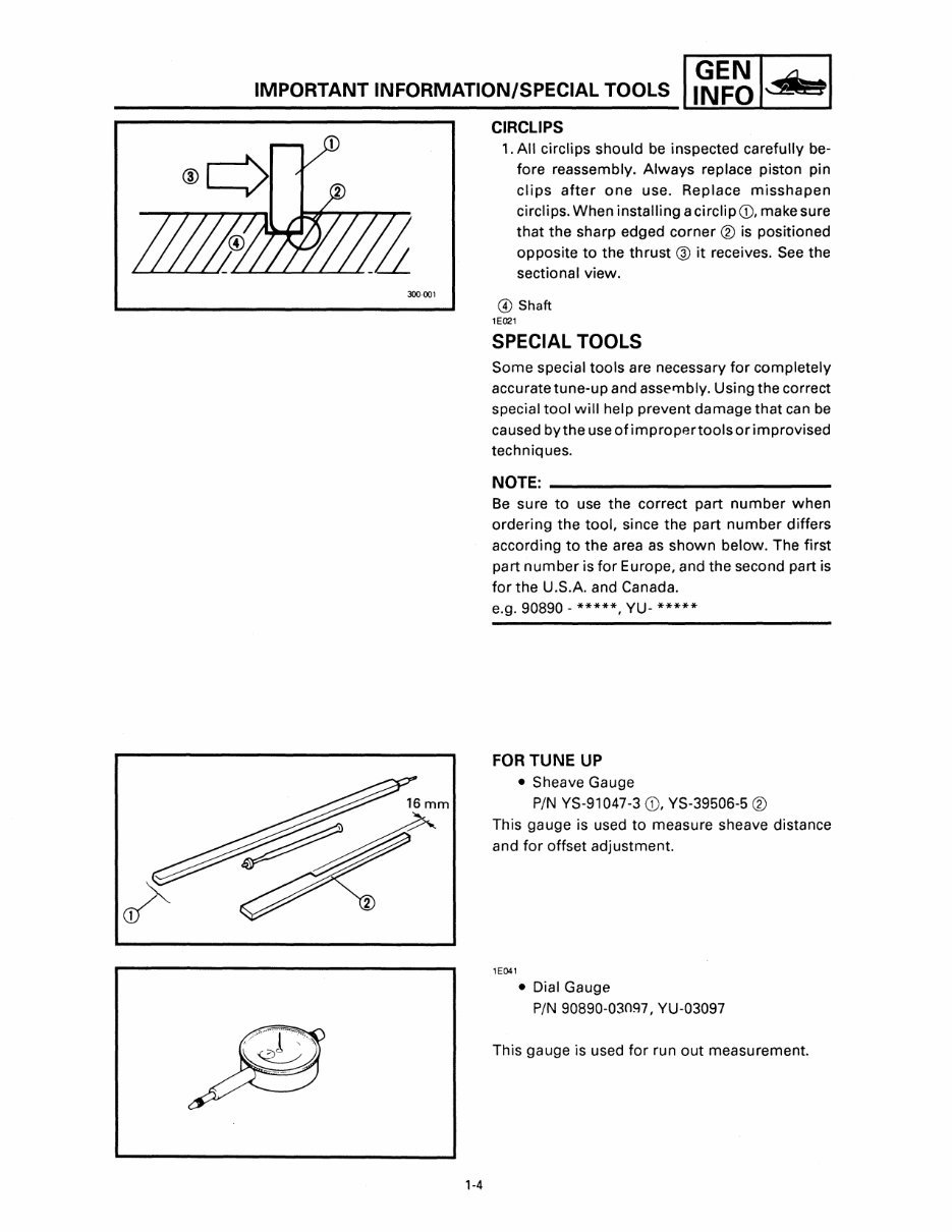
1. All circlips should be inspected carefully be-
fore reassembly. Always replace piston pin
clips after one use. Replace misshapen
circlips. When installing a circlip G), make sure
that the sharp edged corner ® is positioned
opposite to the thrust ® it receives. See the
sectional view.
@ Shaft
lE021
SPECIAL TOOLS
Some special tools are necessary for completely
accurate tune-up and assembly. Using the correct
special tool will help prevent damage that can be
caused by the use of improper tools or improvised
techniques.
NOTE: ______________________ _
Be sure to use the correct part number when
ordering the tool, since the part number differs
according to the area as shown below. The first
part number is for Europe, and the second part is
for the U.S.A. and Canada.
e.g. 90890 - *****, YU- *****
FORTUNE UP
• Sheave Gauge
PIN YS-91047-3 G), YS-39506-5 ®
This gauge is used to measure sheave distance
and for offset adjustment.
lE041
• Dial Gauge
PIN 90890-03097, YU-03097
This gauge is used for run out measurement.
1-5
SPECIAL TOOLS I ~~~ I~ I
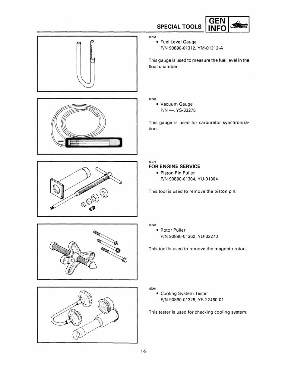
lE051
• Fuel Level Gauge
PIN 90890-01312, YM-01312-A
This gauge is used to measure the fuel level in the
float chamber.
lE061
• Vacuum Gauge
PIN -, YS-33275
This gauge is used for carburetor synchroniza-
tion.
1 E071
FOR ENGINE SERVICE
• Piston Pin Puller
PIN 90890-01304, YU-01304
This tool is used to remove the piston pin.
lE081
• Rotor Puller
PIN 90890-01362, YU-33270
This tool is used to remove the magneto rotor.
lE091
• Cooling System Tester
PIN 90890-01325, YS-22460-01
This tester is used for checking cooling system.
'-6
SPECIAL TOOLS II~~~ I~ I
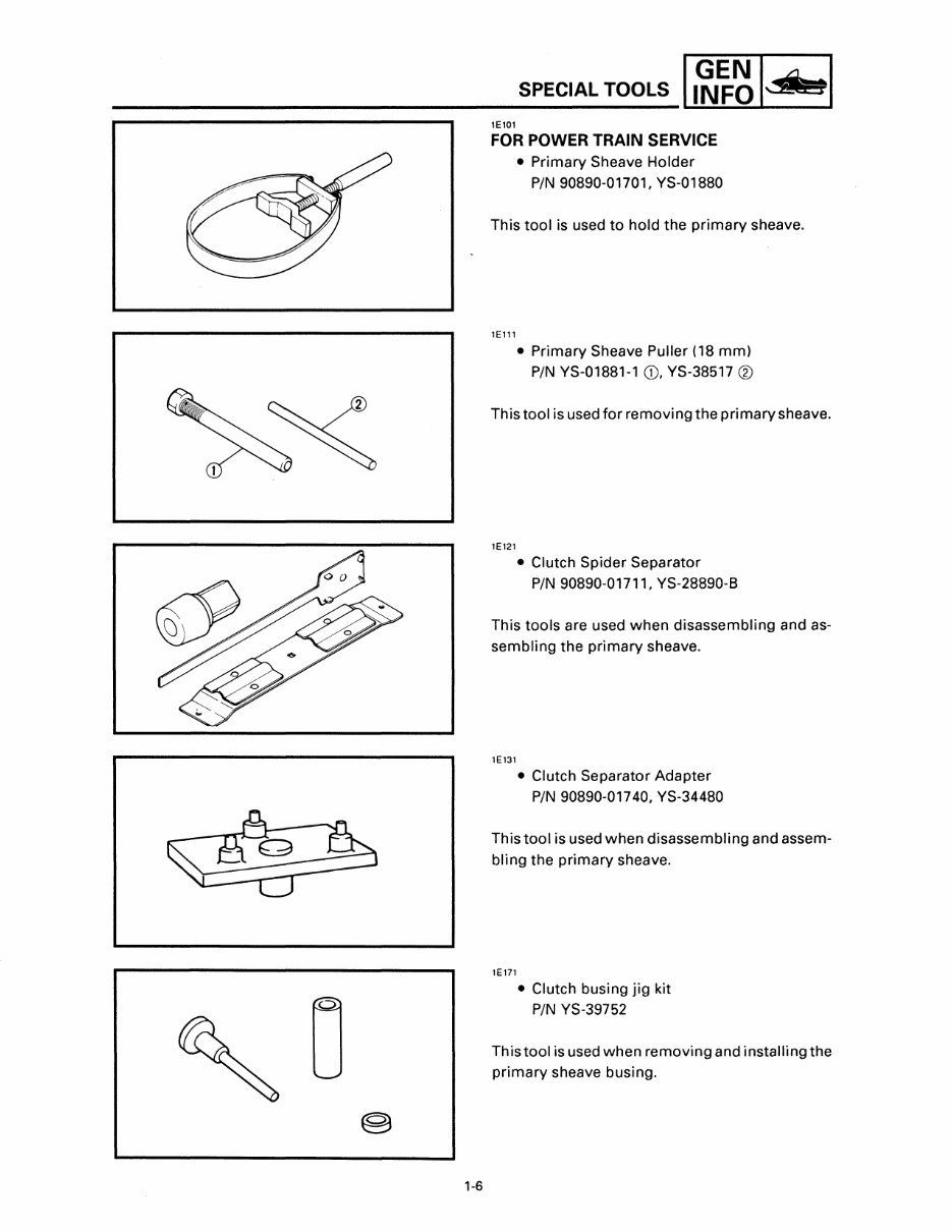
lEl0l
FOR POWER TRAIN SERVICE
• Primary Sheave Holder
PIN 90890-01701, YS-01880
This tool is used to hold the primary sheave.
lElll
• Primary Sheave Puller (18 mm)
PIN YS-01881-1 CD, YS-38517 ®
Thistool is used for removing the primary sheave.
lE121
• Clutch Spider Separator
PIN 90890-01711, YS-28890-8
This tools are used when disassembling and as-
sembling the primary sheave.
lE131
• Clutch Separator Adapter
PIN 90890-01740, YS-34480
This tool is used when disassembling and assem-
bling the primary sheave.
lE171
• Clutch busing jig kit
PIN YS-39752
Thistool is used when removing and installing the
primary sheave busing.
1-7
SPECIAL TOOLS II~~~ ISs I
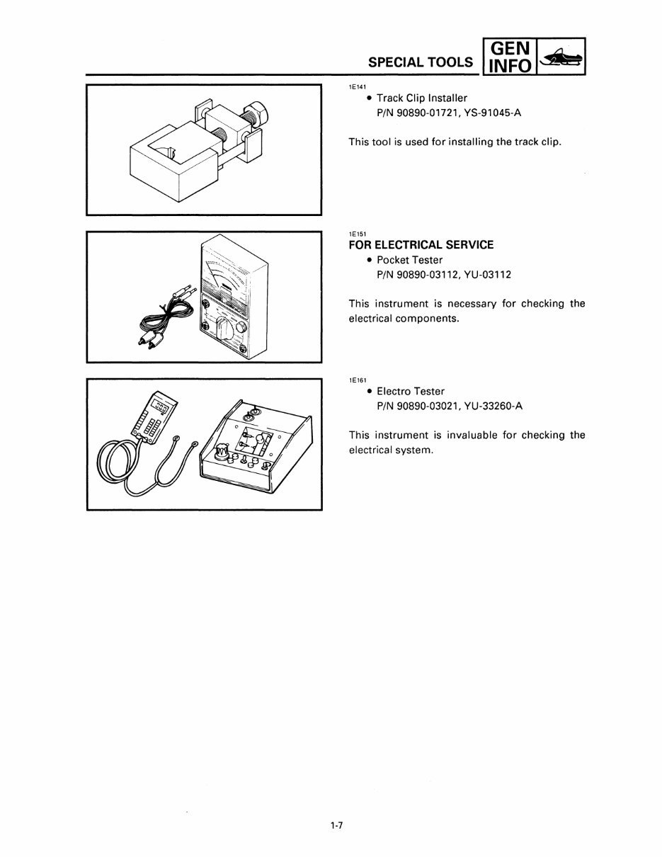
1E141
• Track Clip Installer
PIN 90890-01721. YS-91045-A
This tool is used for installing the track clip.
1E151
FOR ELECTRICAL SERVICE
• Pocket Tester
PIN 90890-03112. YU-03112
This instrument is necessary for checking the
electrical components.
1E161
• Electro Tester
PIN 90890-03021. YU-33260-A
This instrument is invaluable for checking the
electrical system.
You're Reading a Preview
What's Included?
 Lifetime Access
Fast Download Speeds
Online & Offline Access
Access PDF Contents & Bookmarks
Full Search Facility
Print one or all pages of your manual
$31.99
2000 Yamaha V Max 600 Deluxe (Elec. Start) Service & Repair Manual
Viewed 16 Times Today

What's Included?
Lifetime Access
Fast Download Speeds
Online & Offline Access
Access PDF Contents & Bookmarks
Full Search Facility
Print one or all pages of your manual
$31.99

Secure transaction
What's Included?
Lifetime Access
Fast Download Speeds
Online & Offline Access
Access PDF Contents & Bookmarks
Full Search Facility
Print one or all pages of your manual
Description
The Yamaha V-Max 600 Deluxe (Electric Start) Service and Repair Manual provides detailed information for technicians, mechanics, and DIY enthusiasts to effectively diagnose, repair, and maintain this powerful motorcycle. This comprehensive guide covers all aspects of its technical specifications, system overviews, and troubleshooting procedures.
- Contains detailed diagrams, illustrations, and specifications for engine, transmission, brakes, suspension, and electrical systems
- Step-by-step repair procedures for common issues and periodic maintenance tasks, including oil changes, tire rotations, and brake pad replacements
- Systematic troubleshooting and diagnostic techniques for identifying and correcting problems
- Key data such as torque specifications, tolerances, and wear limits for critical components
- A valuable resource for professionals and hobbyists alike, covering both the "how-to" and "why" aspects of motorcycle repair and maintenance
This manual is suitable for both experienced mechanics and DIY enthusiasts looking to develop their skills and understanding of the Yamaha V-Max 600 Deluxe (Electric Start). It provides a comprehensive and authoritative source of information, essential for anyone seeking to maintain, repair, or restore their motorcycle to optimal performance and condition.


