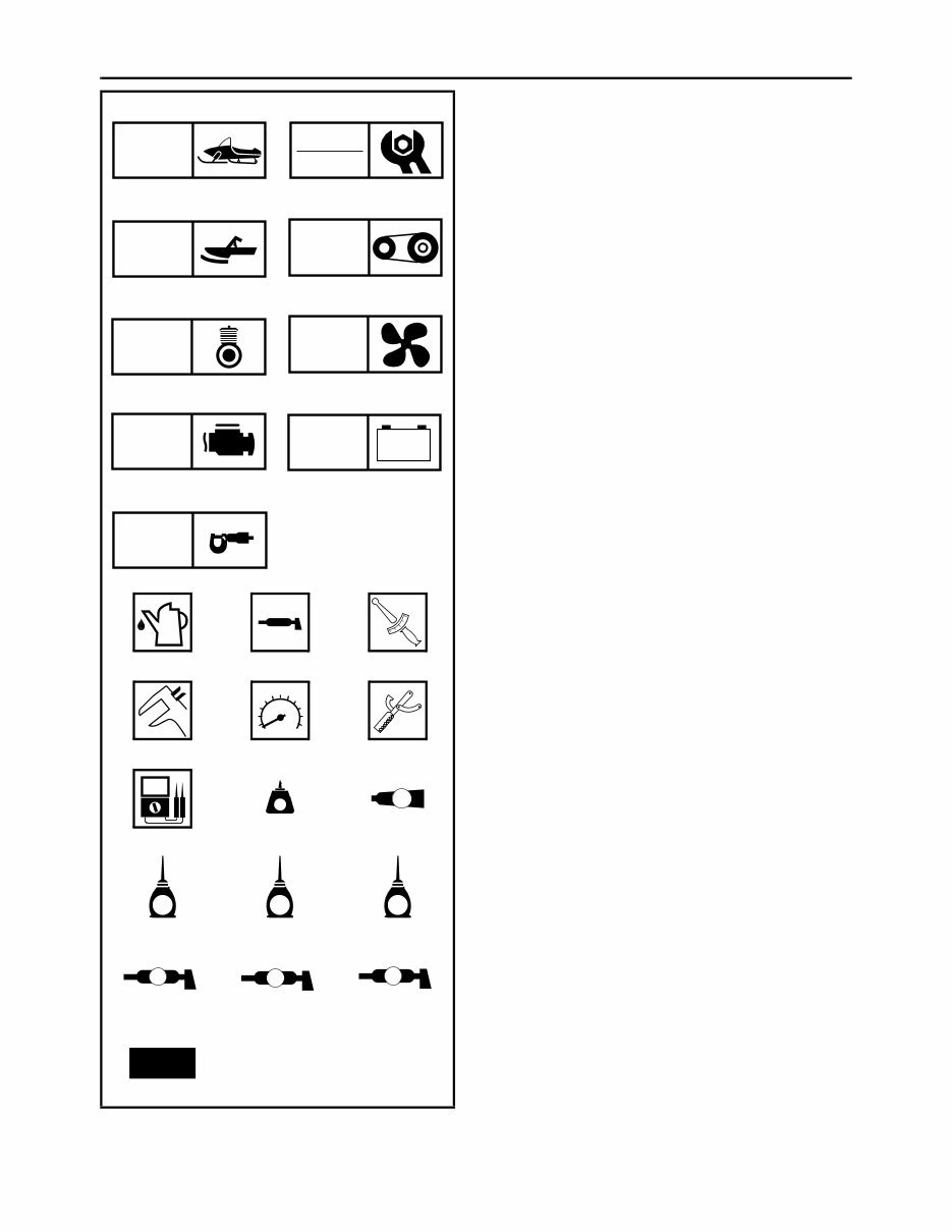
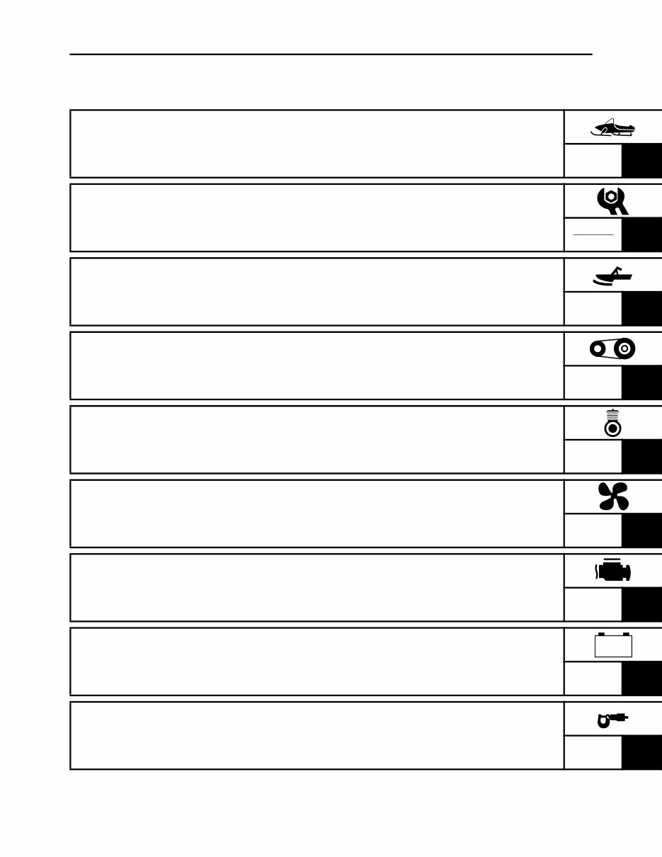
ILLUSTRATED SYMBOLS (Refer to the illustration) Illustrated symbols 1 to 9 are designed as thumb tabs to indicate the chapter’s number and content. 1 General information 2 Periodic inspection and adjustment 3 Chassis 4 Power train 5 Engine 6 Cooling system 7 Fuel injection system 8 Electrical 9 Specifications Illustrated symbols 0 to F are used to identify the specifications which appear. 0 Filling fluid A Lubricant B Tightening C Wear limit, clearance D Engine speed E Special tool F Ω, V, A Illustrated symbols G to O in the exploded diagram indicate grade of lubricant and location of lubrica- tion point. G Apply locking agent (LOCTITE ® ) H Apply Yamabond No.5 ® I Apply engine oil J Apply gear oil K Apply molybdenum disulfide oil L Apply wheel bearing grease M Apply low-temperature lithium-soap base grease N Apply molybdenum disulfide grease O Use new one 1 2 3 4 5 6 7 8 9 0 A B C D E F G H I J K L M N O GEN INFO INSP ADJ CHAS POWR TR ENG COOL FI – + ELEC SPEC T R . . LT 5 E G M B LS M New
INDEX GENERAL INFORMATION GEN INFO 1 PERIODIC INSPECTION AND ADJUSTMENT INSP ADJ 2 CHASSIS CHAS 3 POWER TRAIN POWR TR 4 ENGINE ENG 5 COOLING SYSTEM COOL 6 FUEL INJECTION SYSTEM FI 7 ELECTRICAL ELEC 8 SPECIFICATIONS SPEC 9 – +
CHAPTER 1. GENERAL INFORMATION MACHINE IDENTIFICATION............................ 1-1 FRAME SERIAL NUMBER ......................... 1-1 ENGINE SERIAL NUMBER ........................ 1-1 IMPORTANT INFORMATION .......................... 1-2 PREPARATION FOR REMOVAL AND DISASSEMBLY........................................... 1-2 ALL REPLACEMENT PARTS..................... 1-2 GASKETS, OIL SEALS, AND O-RINGS..... 1-3 LOCK WASHERS/PLATES AND COTTER PINS............................................................ 1-3 BEARINGS AND OIL SEALS ..................... 1-3 CIRCLIPS ................................................... 1-3 LOCTITE ® ................................................... 1-3 SPECIAL TOOLS ............................................. 1-4 FOR TUNE UP............................................ 1-4 FOR ENGINE SERVICE ............................. 1-4 FOR POWER TRAIN SERVICE ................. 1-7 FOR FUEL INJECTION SERVICE ............. 1-8 FOR ELECTRICAL SERVICE .................... 1-8 CHAPTER 2. PERIODIC INSPECTION AND ADJUSTMENT INTRODUCTION............................................... 2-1 PERIODIC MAINTENANCE CHART FOR THE EMISSION CONTROL SYSTEM.............. 2-1 GENERAL MAINTENANCE AND LUBRICATION CHART .................................... 2-2 ENGINE ............................................................ 2-4 SPARK PLUGS........................................... 2-4 FUEL LINE INSPECTION ........................... 2-4 COOLING SYSTEM.................................... 2-5 VALVE CLEARANCE ADJUSTMENT ........ 2-7 THROTTLE BODY SYNCHRONIZATION ............................... 2-13 ENGINE IDLE SPEED ADJUSTMENT ..... 2-14 THROTTLE CABLE FREE PLAY ADJUSTMENT .......................................... 2-15 THROTTLE OVERRIDE SYSTEM (T.O.R.S.) CHECK .................................... 2-16 COMPRESSION PRESSURE MEASUREMENT ...................................... 2-17 ENGINE OIL LEVEL INSPECTION .......... 2-19 ENGINE OIL REPLACEMENT ................. 2-20 CYLINDER HEAD BREATHER HOSE INSPECTION ............................................ 2-23 THROTTLE BODY JOINTS INSPECTION ............................................ 2-23 CHECKING THE AIR FILTER ELEMENT ................................................. 2-24 EXHAUST SYSTEM INSPECTION .......... 2-25 POWER TRAIN............................................... 2-26 SHEAVE OFFSET ADJUSTMENT ........... 2-26 DRIVE V-BELT.......................................... 2-28 ENGAGEMENT SPEED CHECK .............. 2-29 PARKING BRAKE ADJUSTMENT............ 2-29 BRAKE FLUID LEVEL INSPECTION ....... 2-30 BRAKE PAD INSPECTION....................... 2-31 BRAKE HOSE INSPECTION .................... 2-32 AIR BLEEDING (HYDRAULIC BRAKE SYSTEM) .................................................. 2-32 DRIVE CHAIN ........................................... 2-33 TRACK TENSION ADJUSTMENT ............ 2-35 SLIDE RUNNER INSPECTION ................ 2-37 MAXIMIZING DRIVE TRACK LIFE ........... 2-37 CHASSIS ........................................................ 2-39 SKI/SKI RUNNER ..................................... 2-39 STEERING SYSTEM ................................ 2-39 LUBRICATION .......................................... 2-41 ELECTRICAL ................................................. 2-42 HEADLIGHT BEAM ADJUSTMENT ......... 2-42 BATTERY INSPECTION........................... 2-42 FUSE INSPECTION.................................. 2-48 TUNING .......................................................... 2-50 CLUTCH.................................................... 2-50 GEAR SELECTION................................... 2-55 FRONT SUSPENSION ............................. 2-61 REAR SUSPENSION................................ 2-63 CHAPTER 3. CHASSIS COWLINGS ...................................................... 3-1 PZ50/PZ50GT/PZ50FX/PZ50M .................. 3-1 PZ50VT/PZ50MP ........................................ 3-3 STEERING ........................................................ 3-4 PZ50W/PZ50GT/PZ50FX/PZ50M............... 3-4 PZ50VT/PZ50MP ........................................ 3-6 REMOVAL................................................. 3-10 INSPECTION ............................................ 3-10 INSTALLATION......................................... 3-11 SKI .................................................................. 3-14 PZ50/PZ50GT/PZ50FX/PZ50VT “USA/ Canada” .................................................... 3-14
LIGHTING SYSTEM ....................................... 8-22 CIRCUIT DIAGRAM.................................. 8-22 TROUBLESHOOTING .............................. 8-24 BULB(S) .................................................... 8-26 HEADLIGHT BEAM SWITCH ................... 8-26 HEADLIGHT RELAY................................. 8-27 LOAD CONTROL RELAY ......................... 8-27 SIGNAL SYSTEM........................................... 8-28 CIRCUIT DIAGRAM.................................. 8-28 TROUBLESHOOTING .............................. 8-30 BRAKE LIGHT SWITCH ........................... 8-38 DRIVE POSITION SWITCH AND REVERSE POSITION SWITCH (PZ50GT/PZ50FX/PZ50M/PZ50VT/ PZ50MP) ................................................... 8-38 DC BACK BUZZER (PZ50GT/PZ50FX/ PZ50M/PZ50VT/PZ50MP) ........................ 8-38 COOLANT TEMPERATURE SENSOR .... 8-39 OIL LEVEL SWITCH ................................. 8-40 FUEL SENDER ......................................... 8-40 SPEED SENSOR...................................... 8-41 KNOCK SENSOR ..................................... 8-41 GRIP WARMER SYSTEM .............................. 8-42 CIRCUIT DIAGRAM.................................. 8-42 TROUBLESHOOTING .............................. 8-44 GRIP AND THUMB WARMER ................. 8-46 GRIP/THUMB WARMER ADJUSTMENT SWITCH .................................................... 8-46 PASSENGER GRIP WARMER (PZ50VT) .................................................. 8-47 PASSENGER GRIP WARMER SWITCH (PZ50VT) .................................................. 8-47 PASSENGER GRIP WARMER RELAY (PZ50VT/PZ50MP) ................................... 8-48 COOLING SYSTEM (PZ50M/PZ50VT/PZ50MP) ............................. 8-50 CIRCUIT DIAGRAM.................................. 8-50 TROUBLESHOOTING .............................. 8-52 RADIATOR FAN MOTOR ......................... 8-53 RADIATOR FAN MOTOR RELAY ............ 8-53 DRIVE/REVERSE SELECTING SYSTEM (PZ50GT/PZ50FX/PZ50M/PZ50VT/ PZ50MP) ......................................................... 8-54 CIRCUIT DIAGRAM.................................. 8-54 TROUBLESHOOTING .............................. 8-56 GEAR MOTOR ......................................... 8-57 GEAR MOTOR RELAY 1.......................... 8-58 GEAR MOTOR RELAY 2.......................... 8-58 GEAR MOTOR RELAY 3.......................... 8-59 CHAPTER 9. SPECIFICATIONS GENERAL SPECIFICATIONS.......................... 9-1 MAINTENANCE SPECIFICATIONS................. 9-5 ENGINE ...................................................... 9-5 POWER TRAIN ......................................... 9-10 CHASSIS .................................................. 9-16 ELECTRICAL ............................................ 9-18 TIGHTENING TORQUE.................................. 9-21 ENGINE .................................................... 9-21 POWER TRAIN ......................................... 9-23 CHASSIS .................................................. 9-25 GENERAL TORQUE SPECIFICATIONS ....... 9-27 DEFINITION OF UNITS .................................. 9-27 CABLE ROUTING .......................................... 9-29
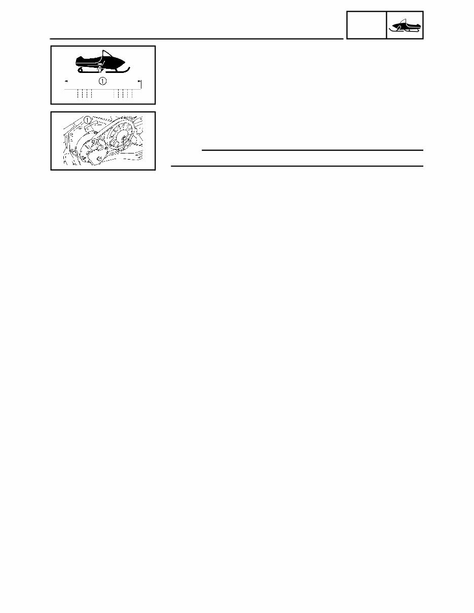
1-1 GEN INFO GENERAL INFORMATION MACHINE IDENTIFICATION FRAME SERIAL NUMBER The frame serial number 1 is located on the right-hand side of the frame (just below the front of the seat). ENGINE SERIAL NUMBER The engine serial number 1 is located on the left-hand side of the crank- case. NOTE: Designs and specifications are subject to change without notice. MACHINE IDENTIFICATION
You're Reading a Preview
What's Included?
Lifetime Access
Fast Download Speeds
Online & Offline Access
Access PDF Contents & Bookmarks
Full Search Facility
Print one or all pages of your manual
$28.99
2007-2008 Yamaha Phazer Venture Lite Service & Repair Manual
2007-2008 PHAZER-VENTURE LITE SNOWMOBILE MODELS COVERED:
2007-2008 Yamaha Phazer and Venture Lite 500cc 4-stroke snowmobiles, venture light PZ50 (PZ-50) PZ50FX PZ50RT PZ50GT PZ50MW PZ50MT mountain lite PZ50VT PZ50MP
Fix-Your-Problems now with this instant service manual. Get the information you need to fix your snowmobile in just seconds in this simple to book. No special software required (works on all computers)!
The Yamaha snowmobile service manual is for the above listed brands and describes the service procedures for the complete snowmobile vehicle. Follow the Maintenance Schedule recommendations to ensure that the snowmobile is in peak operating condition. Performing the scheduled maintenance is very important. It compensates for the initial wear that occurs during the life of the snowmobile.
All chapters in the Yamaha service manual apply to the whole vehicle and illustrate procedures for removal & installation of components that are in detailed step-by-step fashion.
Most all service manual chapters start with an assembly or system illustration, diagrams, exploded parts view, pictures, service information and troubleshooting for the section. The subsequent pages give detailed procedures. If you don't know the source of the trouble, go to the troubleshooting page (sometimes not all sections have a troubleshooting page provided from the manufacture) for a list of causes and effects to determine the problem.
================================= BELOW IS A TYPICAL OUTLINE OF CONTENTS YOU WILL FIND IN A YAMAHA SNOWMOBILE SERVICE MANUAL (INFORMATION WILL DIFFER DEPENDING ON YEAR AND MODEL). =================================









 Lifetime Access




