

1991-1997 Yamaha Venture XL GT & TF Snowmobile Service & Repair Manual
What's Included?
Fast Download Speeds
Online & Offline Access
Access PDF Contents & Bookmarks
Full Search Facility
Print one or all pages of your manual
Q)
®
I~EF~I~I
Irgjl~1
®
@
ICHASI~ I
~141
® ®
IENGIJiI
ICARSI'I
(J)
®
I ElEC I iii I
IAPPXI~'1
®
~
@
~
(jJ)
~
@
~
@
§
®
[ml
@
1
@
1
@
1
m Gl Gl
@ @) @
~ ~ ~
®
A @a
@a
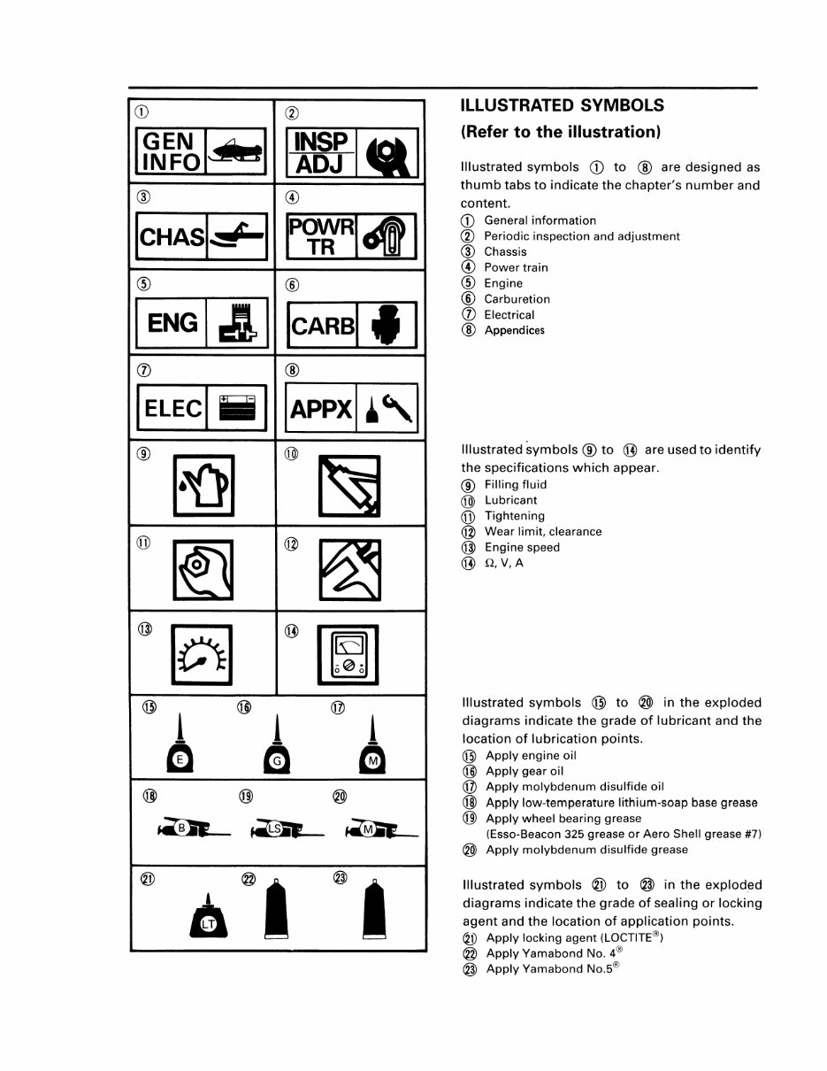
ILLUSTRATED SYMBOLS
(Refer to the illustration)
Illustrated symbols Q) to ® are designed as
thumb tabs to indicate the chapter's number and
content.
Q) General information
® Periodic inspection and adjustment
® Chassis
@ Power train
® Engine
® Carburetion
(J) Electrical
® Appendices
Illustrated symbols ® to ® are used to identify
the specifications which appear.
® Filling fluid
@ Lubricant
(jJ) Tightening
@ Wear limit, clearance
@ Engine speed
® Q,V,A
Illustrated symbols @ to ® in the exploded
diagrams indicate the grade of lubricant and the
location of lubrication points.
@ Apply engine oil
@ Apply gear oil
@ Apply molybdenum disulfide oil
@ Apply low-temperature lithium-soap base grease
(j]) Apply wheel bearing grease
(Esso-Beacon 325 grease or Aero Shell grease #7)
® Apply molybdenum disulfide grease
Illustrated symbols ® to @ in the exploded
diagrams indicate the grade of sealing or locking
agent and the location of application points.
® Apply locking agent (LOCTITE®)
@ Apply Yamabond No. 4®
@ Apply Yamabond No.5®
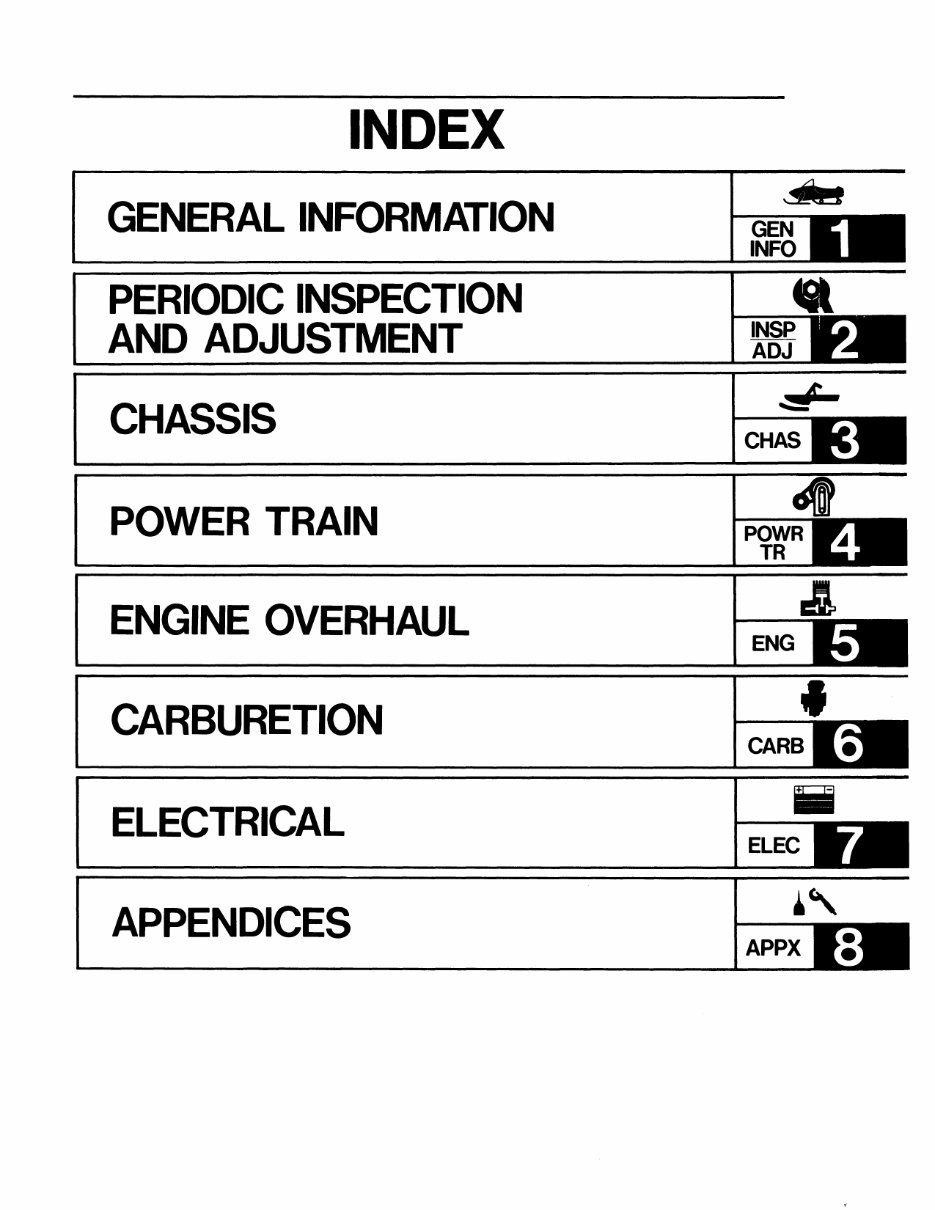
INDEX
GENERAL INFORMATION
PERIODIC INSPECTION
AND ADJUSTMENT
CHASSIS
POWER TRAIN
ENGINE OVERHAUL
CARBURETION
ELECTRICAL
APPENDICES
~
ENG
•
CARB
Iii
ELEC
~,
APPX
______________________________ ~~~I~I
CHAPTER 1.
GENERAL INFORMATION
MACHINE IDENTIFICATION ............................. 1-1
FRAME SERIAL NUMBER ........................... 1-1
ENGINE SERIAL NUMBER ......................... 1-1
IMPORTANT INFORMATION ........................... 1-2
ALL REPLACEMENT PARTS ....................... 1-2
GASKETS, OIL SEALS, AND O-RINGS ...... 1-2
BEARINGS AND OIL SEALS ....................... 1-2
CIRCLIPS ...................................................... 1-2
SPECIAL TOOLS ............................................... 1-3
FOR TUNE UP .............................................. 1-3
FOR ENGINE SERVICE ................................ 1-4
FOR POWER TRAIN SERVICE .................... 1-4
FOR ELECTRICAL SERVICE ........................ 1-6
----
MACHINE IDENTIFICATION I ~~~lujzJl
GENERAL
1-1
INFORMATION
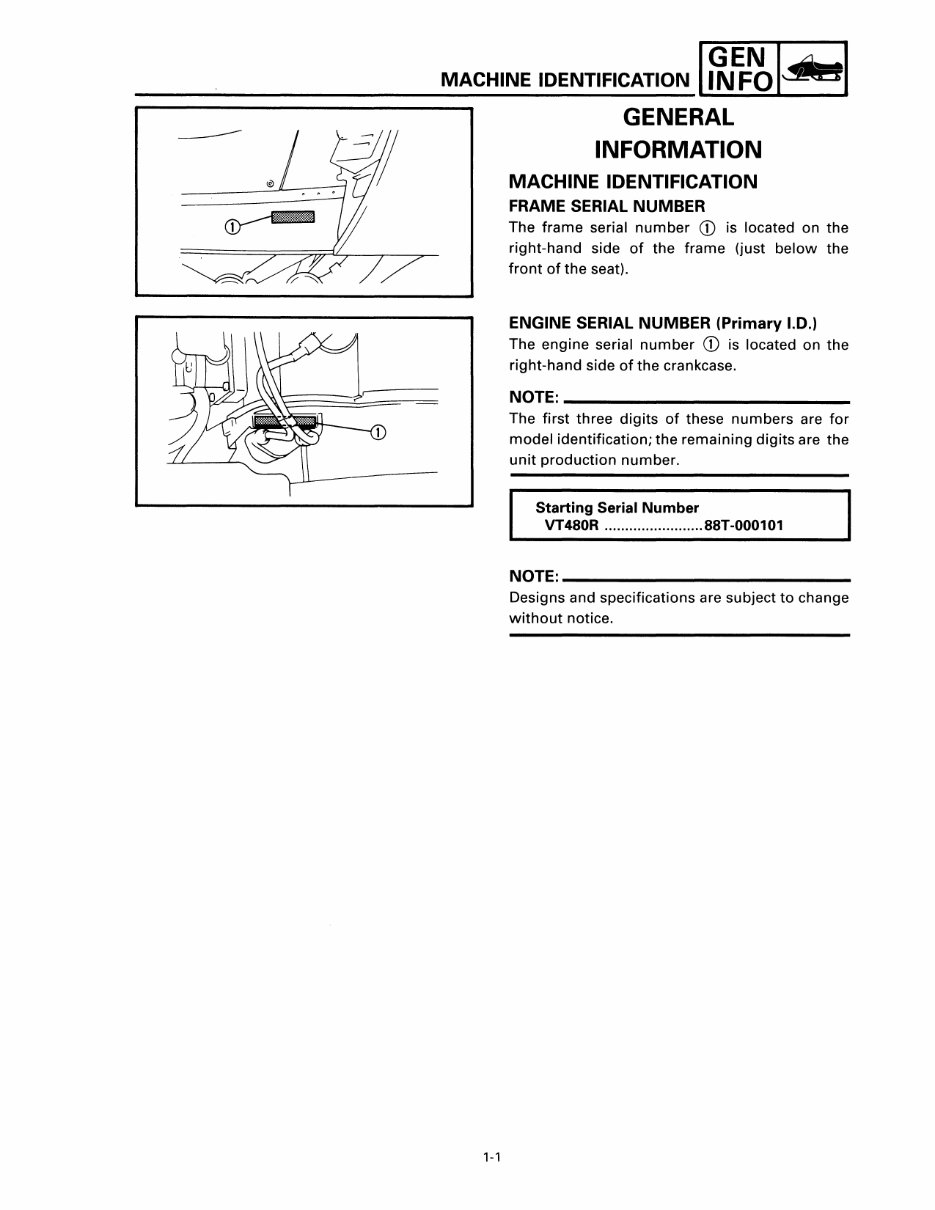
MACHINE IDENTIFICATION
FRAME SERIAL NUMBER
The frame serial number CD is located on the
right-hand side of the frame (just below the
front of the seat).
ENGINE SERIAL NUMBER (Primary I.D.'
The engine serial number CD is located on the
right-hand side of the crankcase.
NOTE: ______________________ _
The first three digits of these numbers are for
model identification; the remaining digits are the
unit production number.
Starting Serial Number
VT480R ........................ 88T-000101
NOTE: _____________________ __
Designs and specifications are subject to change
without notice.
IMPORTANT INFORMATION I g.EF~I*'1
IMPORTANT INFORMATION
300-002
300-003
300-001
1-2
ALL REPLACEMENT PARTS
1. We recommend the use of Yamaha genuine
parts for all replacements. Use oil and/or
grease recommended by Yamaha for assem-
bly and adjustment.
GASKETS, OIL SEALS, AND a-RINGS
1. All gaskets, seals, and O-rings should be re-
placed when an engine is overhauled. All
gasket surfaces, oil seal lips, and O-rings
must be cleaned.
2. Properly oil all mating parts and bearings
during reassembly. Apply grease to the oil
seal lips.
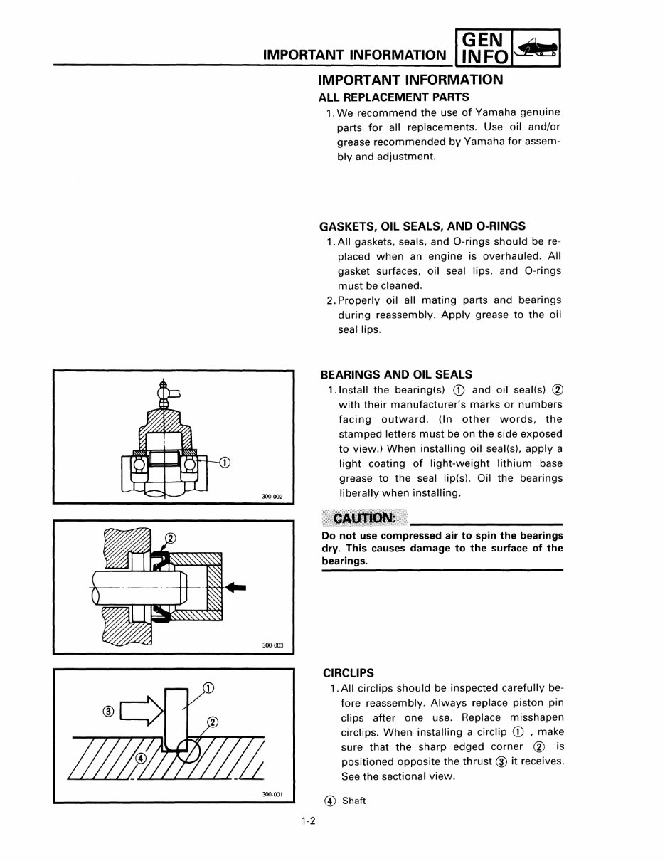
BEARINGS AND OIL SEALS
1.lnstall the bearing(s) CD and oil seal(s) ®
with their manufacturer's marks or numbers
facing outward. (In other words, the
stamped letters must be on the side exposed
to view.) When installing oil seal(s), apply a
light coating of light-weight lithium base
grease to the seal lip(s). Oil the bearings
liberally when installing.
Do not use compressed air to spin the bearings
dry. This causes damage to the surface of the
bearings.
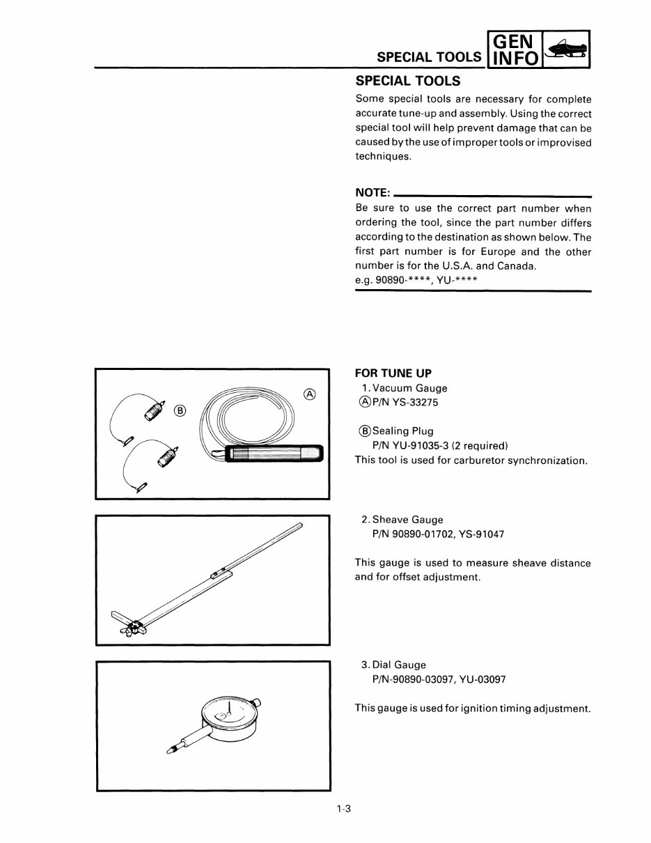
CIRCUPS
1.AII circlips should be inspected carefully be-
fore reassembly. Always replace piston pin
clips after one use. Replace misshapen
circlips. When installing a circlip CD , make
sure that the sharp edged corner ® is
positioned opposite the thrust ® it receives.
See the sectional view.
@ Shaft
1-3
SPECIAL TOOLS I~EF~IJtztI
SPECIAL TOOLS
Some special tools are necessary for complete
accurate tune-up and assembly. Using the correct
special tool will help prevent damage that can be
ca used by the use of improper tools or im provised
techniques.
NOTE: ______________________ __
Be sure to use the correct part number when
ordering the tool, since the part number differs
according to the destination as shown below. The
first part number is for Europe and the other
number is for the U.S.A. and Canada.
e.g. 90890-****, YU-****
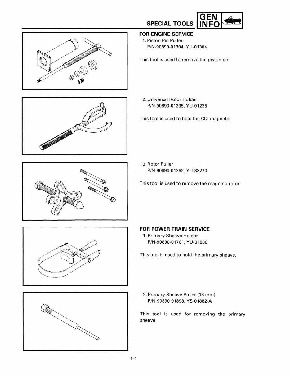
FORTUNE UP
1. Vacuum Gauge
®P/N YS-33275
®Sealing Plug
PIN YU-91035-3 (2 required)
This tool is used for carburetor synchronization.
2. Sheave Gauge
PIN 90890-01702, YS-91047
This gauge is used to measure sheave distance
and for offset adjustment.
3. Dial Gauge
P/N-90890-03097, YU-03097
This gauge is used for ignition timing adjustment.
I
GINEFNOldwl
SPECIAL TOOLS ~
-------------------------------------------------------
1-4
FOR ENGINE SERVICE
1. Piston Pin Puller
P/N-90890-01304, YU-01304
This tool is used to remove the piston pin.
2. Universal Rotor Holder
P/N-90890-01235, YU-01235
This tool is used to hold the CDI magneto.
3. Rotor Puller
P/N-90890-0 1362, YU-33270
This tool is used to remove the magneto rotor.
FOR POWER TRAIN SERVICE
1. Primary Sheave Holder
P/N-90890-01701, YU-01880
This tool is used to hold the primary sheave.
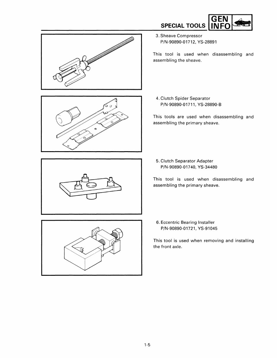
2. Primary Sheave Puller (18 mm)
P/N-90890-01898, YS-01882-A
This tool is used for removing the primary
sheave.
1-5
SPECIAL TOOLS I ~ EF~ jJa I
3. Sheave Compressor
P/N-90890-01712, YS-28891
This tool is used when disassembling and
assembling the sheave.
4. Clutch Spider Separator
P/N-90890-01711, YS-28890-B
This tools are used when disassembling and
assembling the primary sheave.
5. Clutch Separator Adapter
P/N-90890-01740, YS-34480
This tool is used when disassembling and
assembling the primary sheave.
6. Eccentric Bearing Installer
P/N-90890-01721, YS-91045
This tool is used when removing and installing
the front axle.
1-6
SPECIAL TOOLS I~EF~IJsI
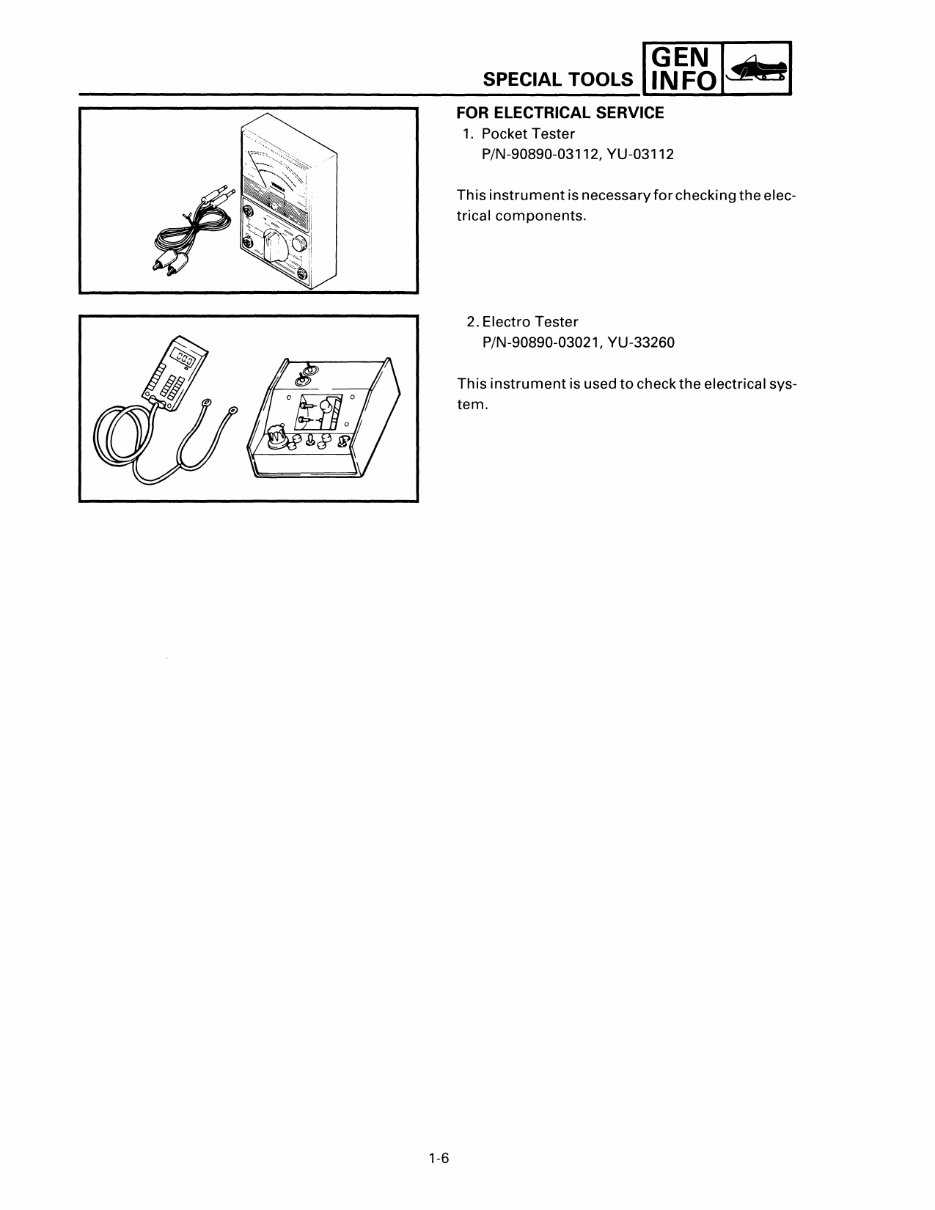
FOR ELECTRICAL SERVICE
1. Pocket Tester
P/N-90890-03112, YU-03112
Th is instrument is necessa ry for checki ng the elec-
trical components.
2. Electro Tester
P/N-90890-03021, YU-33260
This instrument is used to check the electrical sys-
tem.
_________ lrgr ~1
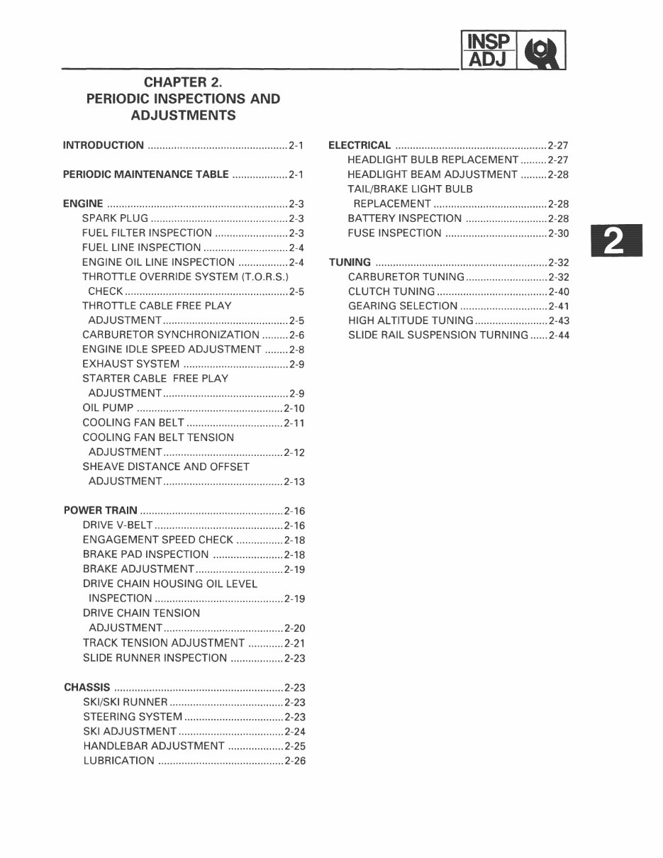
CHAPTER 2.
PERIODIC INSPECTIONS AND
ADJUSTMENTS
INTRODUCTION ................................................ 2-1
PERIODIC MAINTENANCE TABLE ................... 2-1
ENGINE .............................................................. 2-3
SPARK PLUG ............................................... 2-3
FUEL FILTER INSPECTION ......................... 2-3
FUEL LINE INSPECTION ............................. 2-4
ENGINE OIL LINE INSPECTION ................. 2-4
THROTTLE OVERRIDE SYSTEM (T.O.R.S.)
CHECK ........................................................ 2-5
THROTTLE CABLE FREE PLAY
ADJUSTMENT ........................................... 2-5
CARBURETOR SYNCHRONIZATION ......... 2-6
ENGINE IDLE SPEED ADJUSTMENT ........ 2-8
EXHAUST SYSTEM .................................... 2-9
STARTER CABLE FREE PLAY
ADJUSTMENT ........................................... 2-9
OIL PUMP .................................................. 2-10
COOLING FAN BELT ................................. 2-11
COOLING FAN BELT TENSION
ADJUSTMENT ......................................... 2-12
SHEAVE DISTANCE AND OFFSET
ADJUSTMENT ......................................... 2-13
POWER TRAIN ................................................. 2-16
DRIVE V-BELT ............................................ 2-16
ENGAGEMENT SPEED CHECK ................ 2-18
BRAKE PAD INSPECTION ........................ 2-18
BRAKE ADJUSTMENT .............................. 2-19
DRIVE CHAIN HOUSING OIL LEVEL
INSPECTION ............................................ 2-19
DRIVE CHAIN TENSION
ADJUSTMENT ......................................... 2-20
TRACK TENSION ADJUSTMENT ............ 2-21
SLIDE RUNNER INSPECTION .................. 2-23
CHASSIS .......................................................... 2-23
SKI/SKI RUNNER ....................................... 2-23
STEERING SYSTEM .................................. 2-23
SKI ADJUSTMENT .................................... 2-24
HANDLEBAR ADJUSTMENT ................... 2-25
LUBRICATION ........................................... 2-26
ELECTRICAL .................................................... 2-27
HEADLIGHT BULB REPLACEMENT ......... 2-27
HEADLIGHT BEAM ADJUSTMENT ......... 2-28
TAIL/BRAKE LIGHT BULB
REPLACEMENT ....................................... 2-28
BATTERY INSPECTION ............................ 2-28
FUSE INSPECTION ................................... 2-30
TUNING ........................................................... 2-32
CARBURETOR TUNING ............................ 2-32
CLUTCH TUNING ...................................... 2-40
GEARING SELECTION .............................. 2-41
HIGH ALTITUDE TUNING ......................... 2-43
SLIDE RAIL SUSPENSION TURNING ...... 2-44
You're Reading a Preview
What's Included?
Fast Download Speeds
Online & Offline Access
Access PDF Contents & Bookmarks
Full Search Facility
Print one or all pages of your manual
$31.99
$41.99
Viewed 45 Times Today


Secure transaction
What's Included?
Fast Download Speeds
Online & Offline Access
Access PDF Contents & Bookmarks
Full Search Facility
Print one or all pages of your manual
$31.99
$41.99
- Complete Factory Service Repair Workshop Manual available for instant access on your computer, tablet, or smartphone.
- This Professional Manual covers all repairs, servicing, and troubleshooting procedures, containing step-by-step instructions, highly detailed exploded diagrams, and pictures.
- Useful for both professional Mechanics and Technicians as well as DIY enthusiasts.
- Contains hundreds of pages with detailed photos and diagrams.
- Print out a single page or the entire manual as per your choice.
- Can be used on multiple computers without any limitations or trial periods.
- No expiry dates or renewal fees; can be used for life.
- Fully compatible with all Windows and MAC computers.
Thanks for considering this item. Please click on the button for more information.


