1981-1991 Yamaha SRV540 SRV 540 Snowmobile Service & Repair Manual
What's Included?
Lifetime Access
Fast Download Speeds
Online & Offline Access
Access PDF Contents & Bookmarks
Full Search Facility
Print one or all pages of your manual
1981 SR540E SECTION INDEX GENERAL ENGINE CARBURETION POWER TRAIN CHASSIS ELECTRICAL APPENDIX RACING TIPS
1981 SR540E CHAPTER 1. GENERAL 1-1. EXTERNAL VIEW .......................................................................................................... 1-2 1-2. MACHINE IDENTIFiCATION ...................................................................................... 1-3 A. Frame serial number ............................................................................................ 1-3 B. Engine serial number ........................................................................................... 1-3 1-3. MAINTENANCE INTERVALS CHARTS .................................................................... 1-4 A. Periodic maintenance .......................................................................................... 1-4 B. Lubrication intervals ............................................................................................ 1-5 1-4. HIGH ALTITUDE TUNING .......................................................................................... 1-5
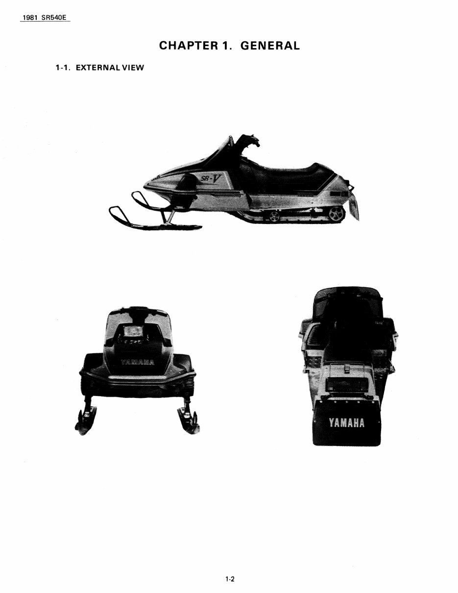
1981 SR540E CHAPTER 1. GENERAL 1-1. EXTERNAL VIEW 1-2
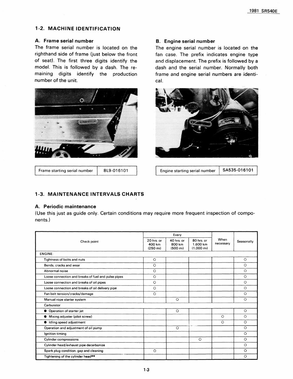
1-2. MACHINE IDENTIFICATION A. Frame serial number The frame serial number is located on the righthand side of frame (just below the front of seat). The first three digits identify the model. This is followed by a dash. The re- maining digits identify the production number of the unit. Frame starting serial number 8L9-016101 1-3. MAINTENANCE INTERVALS CHARTS A. Periodic maintenance 1981 SR540E B. Engine serial number The engine serial number is located on the fan case. The prefix indicates engine type and displacement. The prefix is followed by a dash and the serial number. Normally both frame and engine serial numbers are identi- cal. Engine starting serial number SA535-016101 (Use this just as guide only. Certain conditions may require more frequent inspection of compo- nents.) Every Check point 20 hrs. or 40 hrs. or 80 hrs. or When Seasonally 400km 800km 1.600km necessary (250mi) (500mi) (1.000mi) ENGINE: Tightness of bolts and nuts 0 0 Bends. cracks and wear 0 0 Abnormal noise 0 0 Loose connection and breaks of fuel and pulse pipes 0 0 Loose connection and breaks of oil pipes 0 0 Loose connection and breaks of oil delivery pipe 0 0 Fan belt tension/cracks/damage 0 0 Manual rope starter system 0 0 Carburetor • Operation of starter jet 0 0 • Mixing adjuster (pilot screw) 0 0 • Idling speed adjustment 0 0 .. ,,_. Operation and adjustment of oil pump 0 0 Ignition timing 0 Cylinder compressions 0 0 Cylinder head/exhaust pipe decarbonize 0 Spark plug condition. gap and cleaning 0 0 Tightening of the cylinder head •• 0 1-3
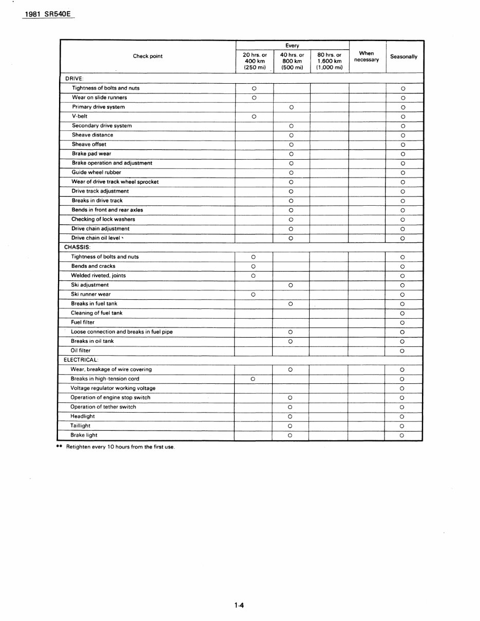
1981 SR540E Every Check point 20 hrs. or 40 hrs. or 80 hrs. or When Seasonally 400km 800km 1.600 km necessary (250mi) (500mi) (1.000mi) DRIVE: Tightness of bolts and nuts 0 0 Wear on slide runners 0 0 Primary drive system 0 0 V-belt 0 0 Secondary drive system 0 0 Sheave distance 0 0 Sheave offset 0 0 8rake pad wear 0 0 Brake operation and adjustment 0 0 Guide wheel rubber 0 0 Wear of drive track wheel sprocket 0 0 Drive track adjustment 0 0 Breaks in drive track 0 0 Bends in front and rear axles 0 0 Checking of lock washers 0 0 Drive chain adjustment 0 0 Drive chain oil level ' 0 0 CHASSIS: Tightness of bolts and nuts 0 0 Bends and cracks 0 0 Welded riveted. joints 0 0 Ski adjustment 0 0 Ski runner wear 0 0 Breaks in fuel tank 0 0 Cleaning of fuel tank 0 Fuel filter 0 Loose connection and breaks in fuel pipe 0 0 Breaks in oil tank 0 0 Oil filter 0 ELECTRICAL: Wear. breakage of wire covering 0 0 Breaks in high-tension cord 0 0 Voltage regulator working voltage 0 Operation of engine stop switch 0 0 Operation of tether switch 0 0 Headlight 0 0 Taillight 0 0 Brake light 0 0 •• Retighten every 10 hours from the first use. 1-4
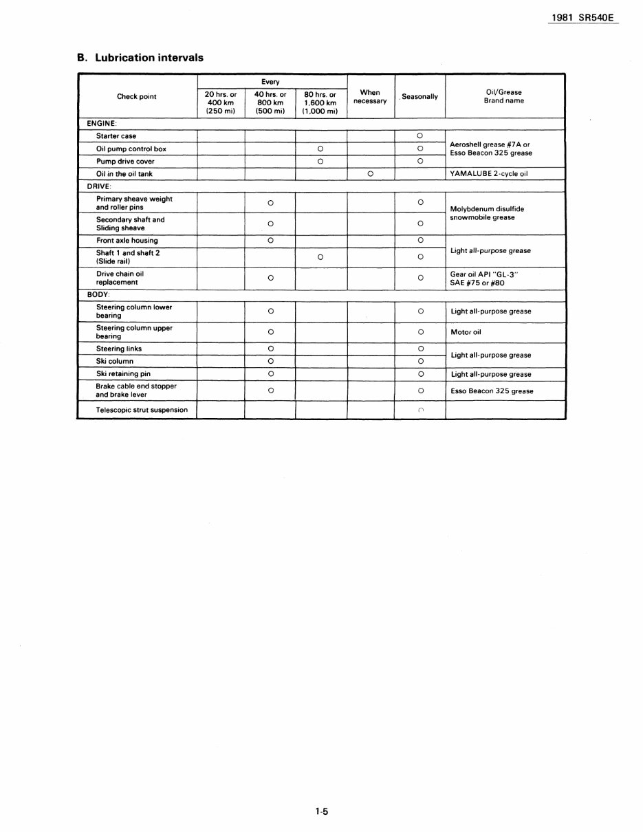
1981 SR540E B. Lubrication intervals Every Check point 20 hrs. or 40 hrs. or 80 hrs. or When . Seasonally Oil/Grease 400km 800km 1.600km necessary Brand name (250mi) (500 mil (1.000 mil ENGINE: Starter case 0 Oil pump contr~1 box 0 0 Aeroshell grease #7 A or Esso Beacon 325 grease Pump drive cover 0 0 Oil in the oil tank 0 YAMAlUBE 2-cycle oil DRIVE: Primary sheave weight 0 0 and roller pins Molybdenum disulfide Secondary shaft and 0 0 snowmobile grease Sliding sheave Front axle housing 0 0 Shaft 1 and shaft 2 0 0 light all-purpose grease (Slide rail) Drive chain oil 0 0 Gear oil API "Gl-3" replacement SAE #75 or #80 BODY: Steering column lower 0 0 light all-purpose grease bearing Steering column upper 0 0 Motor oil bearing Steering links 0 0 Ski column 0 0 light all-purpose grease Ski retaining pin 0 0 light all-purpose grease Brake cable end stopper 0 0 Esso Beacon 325 grease and brake lever Telescopic strut suspension r> 1-5
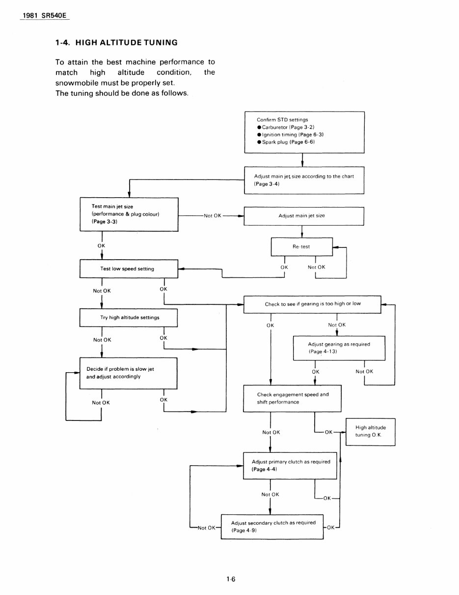
1981 SR540E 1-4. HIGH ALTITUDE TUNING To attain the best machine performance to match high altitude condition. the snowmobile must be properly set. The tuning should be done as follows. J Test main jet size (performance & plug colour! Not OK (Page 3-3) I OK Confirm STD settings .Carburetor (Page 3·21 .Ignition timing (Page 6-31 • Spark plug (Page 6-61 1 Adjust main Jet size according to the chart (Page 3-41 Adjust main jet size ~ I I L-____ !Te_s_t_lo_w_s_p_e_e_d_s_et_ti_n_g __ ,-~~I··--------~~ ______________ -J~K ~ I Not OK Not OK OK Try high altitude settings Not OK Decide if problem is slow jet and adjust accordingly Not OK OK OK Not OK Check to see if gearing is too high or low OK Not OK • Adjust gearing as reqUired (Page 4-131 I OK Check engagement speed and shift performance Not OK OK Adjust primary clutch as required (Page 4-4) Not OK OK I Not OK High altitude tUning O. K. Adjust secondary clutch as required (Page 4-91 OK '-6
1981 SR540E CHAPTER 2. ENGINE 2-1. DiSASSEMBLy ............................................................................................................. 2-2 A. Engine removal ..................................................................................................... 2-2 B. Starter ..................................................................................................................... 2-2 C. Cooling fan ............................................................................................................ 2-3 D. Flywheel magneto ................................................................................................ 2-3 E. Oil pump ................................................................................................................ 2-4 F. Engine disassembly ............................................................................................. 2-5 2-2. INSPECTION, REASSEMBLY AND ADJUSTMENT .............................................. 2-6 A. Engine component ............................................................................................... 2-6 B. Oil pump .............................................................................................................. 2-12 C. Flywheel magneto ............................................................................................. 2-14 D. Cooling fan .......................................................................................................... 2-15 E. Starter. ................................................................................................................. 2-18 F.. Engine remounting ............................................................................................ 2-19
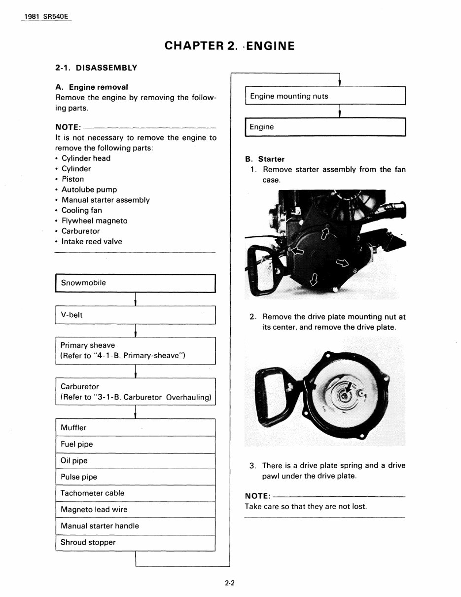
1981 SR540E CHAPTER 2. ·ENGINE 2-1. DISASSEMBLY A. Engine removal Remove the engine by removing the follow- ing parts. NOTE:----------------------~ It is not necessary to remove the engine to remove the following parts: • Cylinder head • Cylinder • Piston • Autolube pump • Manual starter assembly • Cooling fan • Flywheel magneto • Carburetor • Intake reed valve Snowmobile V-belt Primary sheave (Refer to "4-1- B. Primary-sheave") Carburetor (Refer to "3-1-B. Carburetor Overhauling) Muffler Fuel pipe Oil pipe Pulse pipe Tachometer cable Magneto lead wire Manual starter handle Shroud stopper 2-2 Engine mounting nuts Engine B. Starter 1. Remove starter assembly from the fan case . 2. Remove the drive plate mounting nut at its center, and remove the drive plate. 3. There is a drive plate spring and a drive pawl under the drive plate. NOTE:------------------------~ Take care so that they are not lost.
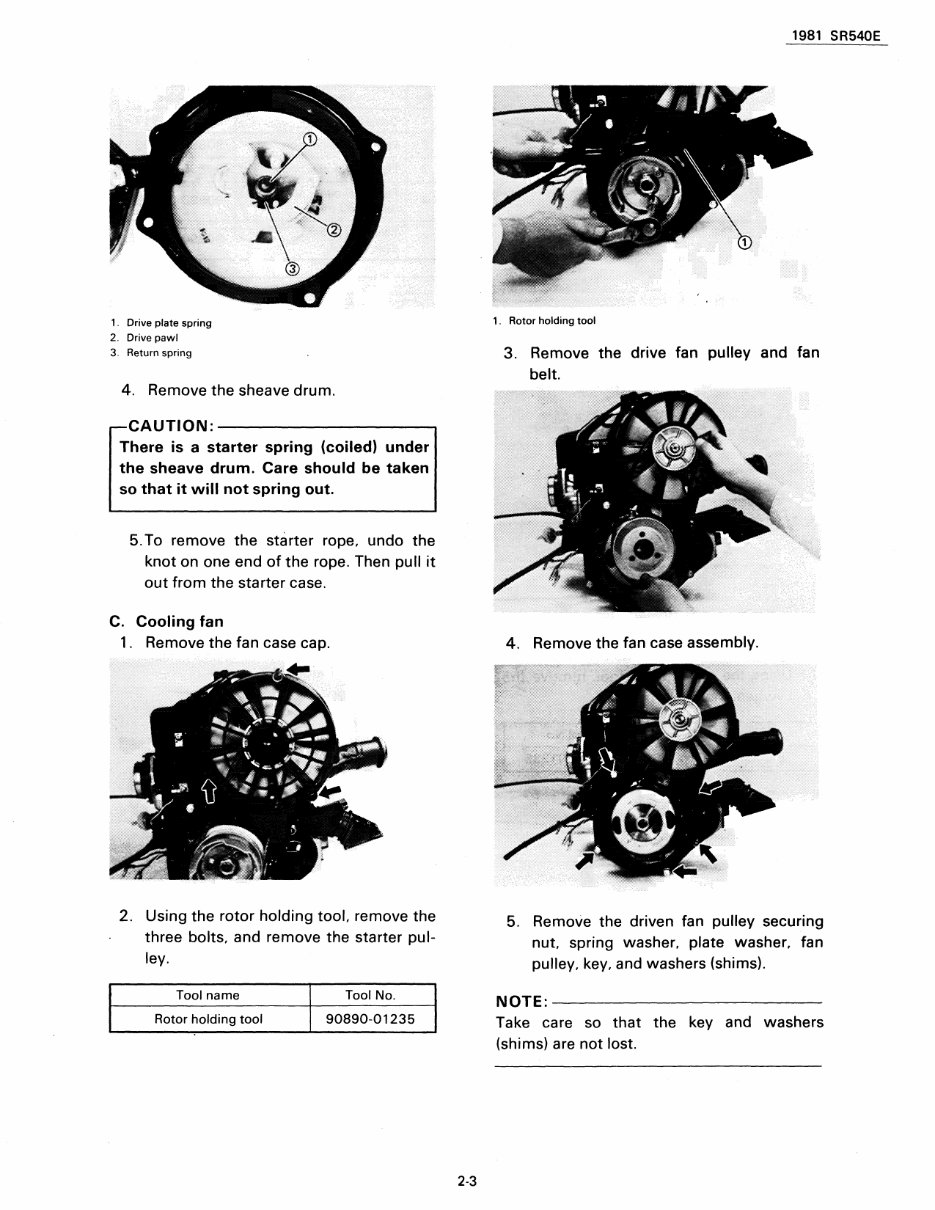
1. Drive plate spring 2. Drive pawl 3. Return spring 4. Remove the sheave drum. CAUTION: -----------. There is a starter spring (coiled) under the sheave drum. Care should be taken so that it will not spring out. 5. To remove the starter rope. undo the knot on one end of the rope. Then pull it out from the starter case. C. Cooling fan 1. Remove the fan case cap. 2. Using the rotor holding tool. remove the three bolts. and remove the starter pul- ley. Tool name Tool No. Rotor holding tool 90890-01235 2-3 1981 SR540E 1. Rotor holding tool 3. Remove the drive fan pulley and fan belt. 4. Remove the fan case assembly. 5. Remove the driven fan pulley securing nut. spring washer. plate washer. fan pulley. key. and washers (shims). NOTE:------------------------- Take care so that the key and washers (shims) are not lost.
The Yamaha SRV540 snowmobile service manual from 1981 to 1991 is a comprehensive resource for all maintenance and repair needs. With a total of 190 pages, this manual is packed with detailed photos, exploded views, and diagrams to assist with step-by-step procedures. It covers a wide range of topics including general information, maintenance and adjustments, engine and transmission, fuel system, cooling system, drivetrain, chassis and brakes, electrical system, wiring diagrams, service information, technical specifications, and troubleshooting and repair.
General Information
Maintenance & Adjustments
Engine & Transmission
Fuel System
Cooling System
Drivetrain
Chassis & Brakes
Electrical System
Wiring Diagrams
Service Information
Technical Specifications
Troubleshooting & Repair
This manual is an invaluable resource for both professional mechanics and DIY enthusiasts who need detailed and reliable information for maintaining and repairing the Yamaha SRV540 snowmobile. It covers a wide range of model years from 1981 to 1991, making it a versatile and essential guide for anyone working on these snowmobiles.
Recently Viewed
5,521,897Happy Clients
2,594,462eManuals
1,120,453Trusted Sellers
15Years in Business
Price:
Actual Price:
1981-1991 Yamaha SRV540 SRV 540 Snowmobile Service & Repair Manual