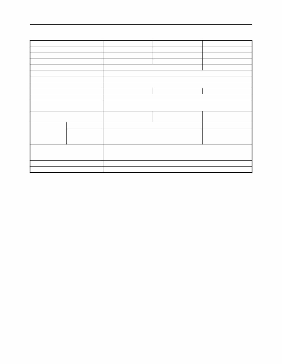
MAJOR SPECIFICATIONS Model RS90GTZ RS90LTGTZ RST90GTZ Model code 8JA1 8JB1 8HF3 Catalogue name RS Vector GT RS Vector L-TX GT RS Venture GT Class Groomed Trail Trail Versatility Touring Seating Capacity One Two Engine type Liquid cooled 4-stroke, 12 valves Cylinder arrangement/Displacement Backward-inclined parallel 3-cylinder/1,049cm 3 Fuel system type Electronic fuel injection Track length 3,072 mm (121 in) 3,456 mm (136 in) 3,648 mm (144 in) Front suspension Independent, double wishbone Front shock absorber 40mm GYTR aluminum HPG with reservoir dual-clicker Rear suspension Mono Shock II RA Mono Shock II RA 136 Pro Comfort CK 144 Rear shock absorber Front — 40mm aluminum HPG Rear 46mm KYB aluminum HPG with remote adjust 40mm aluminum HPG with reservoir compression clicker Ski type Lightweight plastic saddleless middle keel Electric start Standard Reverse Standard
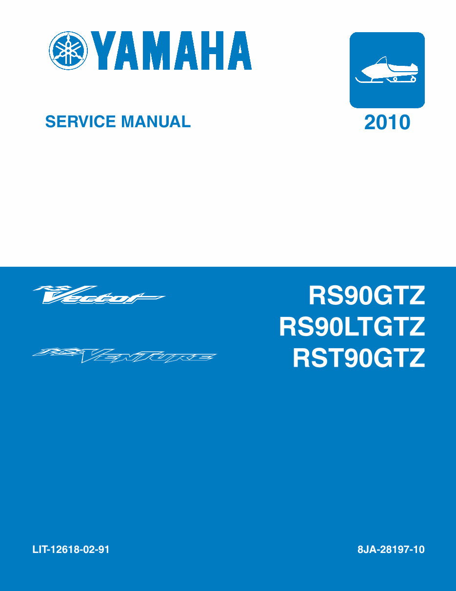
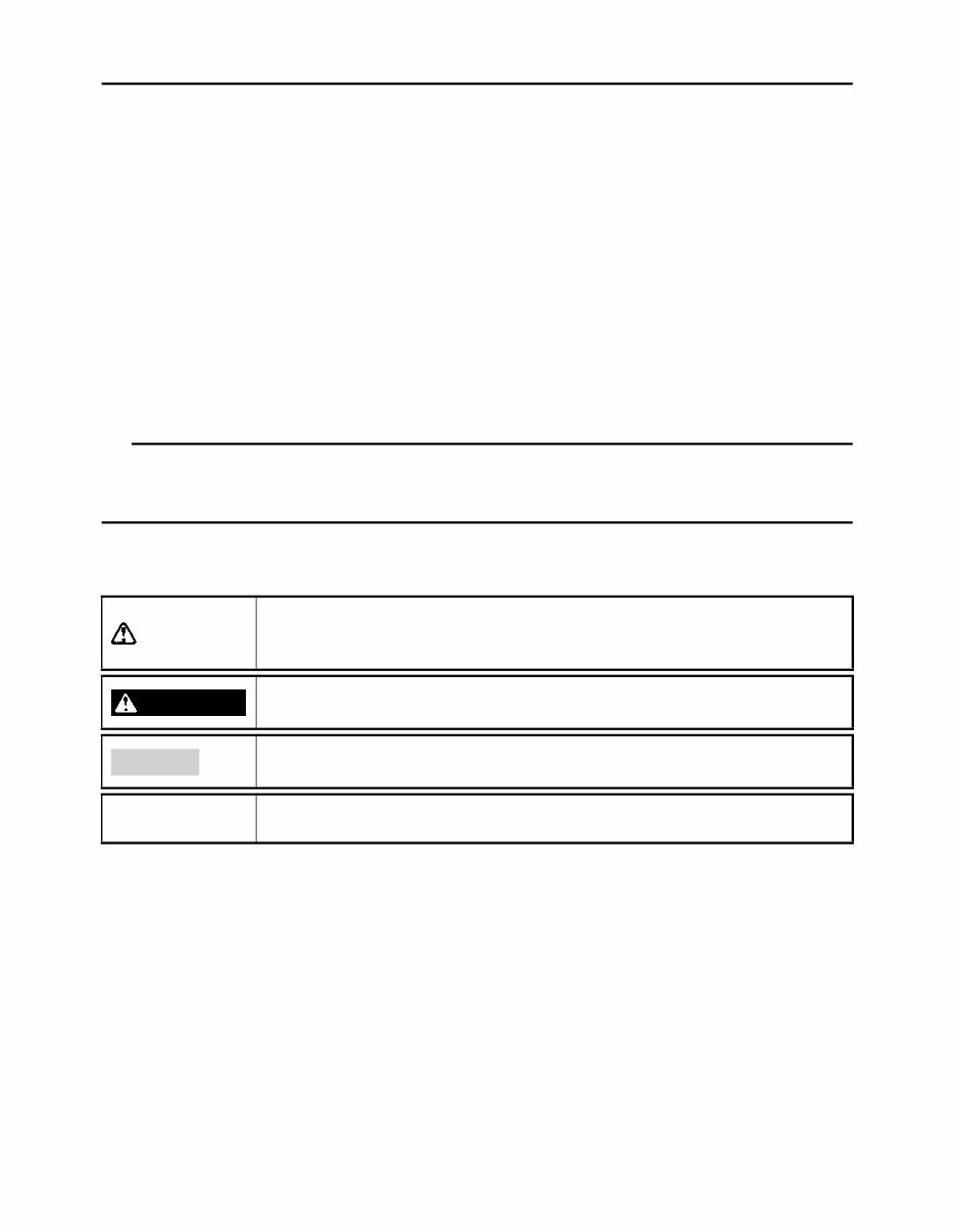
IMPORTANT This manual was produced by the Yamaha Motor Company, Ltd. primarily for use by Yamaha deal- ers and their qualified mechanics. It is not possible to include all the knowledge of a mechanic in one manual. Therefore, anyone who uses this book to perform maintenance and repairs on Yamaha snowmobiles should have a basic understanding of mechanics and the techniques to repair these types of snowmobiles. Repair and maintenance work attempted by anyone without this knowledge is likely to render the snowmobile unsafe and unfit for use. This model has been designed and manufactured to perform within certain specifications in regard to performance and emissions. Proper service with the correct tools is necessary to ensure that the snowmobile will operate as designed. If there is any question about a service procedure, it is imper- ative that you contact a Yamaha dealer for any service information changes that apply to this model. This policy is intended to provide the customer with the most satisfaction from his snowmobile and to conform to federal environmental quality objectives. Yamaha Motor Company, Ltd. is continually striving to improve all of its models. Modifications and significant changes in specifications or procedures will be forwarded to all authorized Yamaha deal- ers and will appear in future editions of this manual where applicable. TIP • This Service Manual contains information regarding periodic maintenance to the emission control system. Please read this material carefully. • Designs and specifications are subject to change without notice. IMPORTANT MANUAL INFORMATION Particularly important information is distinguished in this manual by the following notations. This is the safety alert symbol. It is used to alert you to potential per- sonal injury hazards. Obey all safety messages that follow this symbol to avoid possible injury or death. A WARNING indicates a hazardous situation which, if not avoided, could result in death or serious injury. WARNING A NOTICE indicates special precautions that must be taken to avoid damage to the snowmobile or other property. NOTICE A TIP provides key information to make procedures easier or clearer. TIP
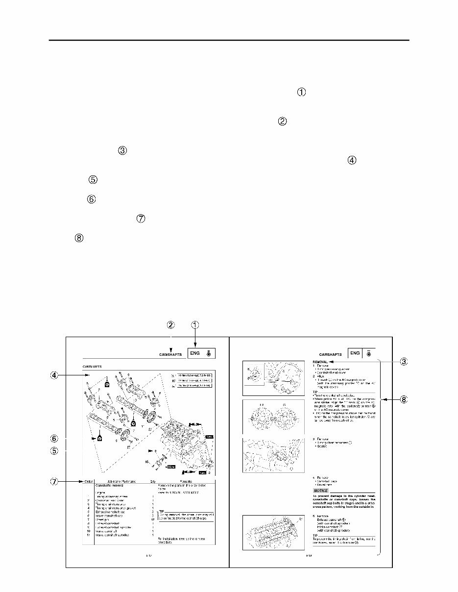
HOW TO USE THIS MANUAL This manual is intended as a handy, easy-to-read reference book for the mechanic. Comprehensive explanations of all installation, removal, disassembly, assembly, repair and check procedures are laid out with the individual steps in sequential order. • The manual is divided into chapters. An abbreviation and symbol in the upper right corner of each page indicate the current chapter. Refer to “SYMBOLS.” • Each chapter is divided into sections. The current section title is shown at the top of each page, except in Chapter 3 (“PERIODIC INSPECTION AND ADJUSTMENT”), where the sub-section title(s) appears. • Sub-section titles appear in smaller print than the section title. •To help identify parts and clarify procedure steps, there are exploded diagrams at the start of each removal and disassembly section. • Numbers are given in the order of the jobs in the exploded diagram. A number indicates a disas- sembly step. • Symbols indicate parts to be lubricated or replaced. Refer to “SYMBOLS”. • A job instruction chart accompanies the exploded diagram, providing the order of jobs, names of parts, notes in jobs, etc. • Jobs requiring more information (such as special tools and technical data) are described sequentially.
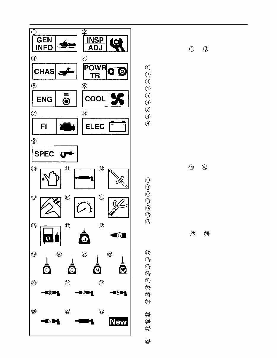
ILLUSTRATED SYMBOLS (Refer to the illustration) Illustrated symbols to are designed as thumb tabs to indicate the chapter’s number and content. General information Periodic inspection and adjustment Chassis Power train Engine Cooling system Fuel injection system Electrical Specifications Illustrated symbols to are used to iden- tify the specifications which appear. Filling fluid Lubricant Tightening torque Wear limit, clearance Engine speed Special tool Electrical data (Ω , V, A) Illustrated symbols to in the exploded diagram indicate grade of lubricant and loca- tion of lubrication point. Apply locking agent (LOCTITE ® ) Apply Yamabond No. 5 ® Apply engine oil Apply gear oil Apply molybdenum disulfide oil Apply brake fluid Apply wheel bearing grease Apply low-temperature lithium-soap-based grease Apply molybdenum disulfide grease Apply silicone grease ESSO beacon 325 grease or Aeroshell grease #7A Use new one
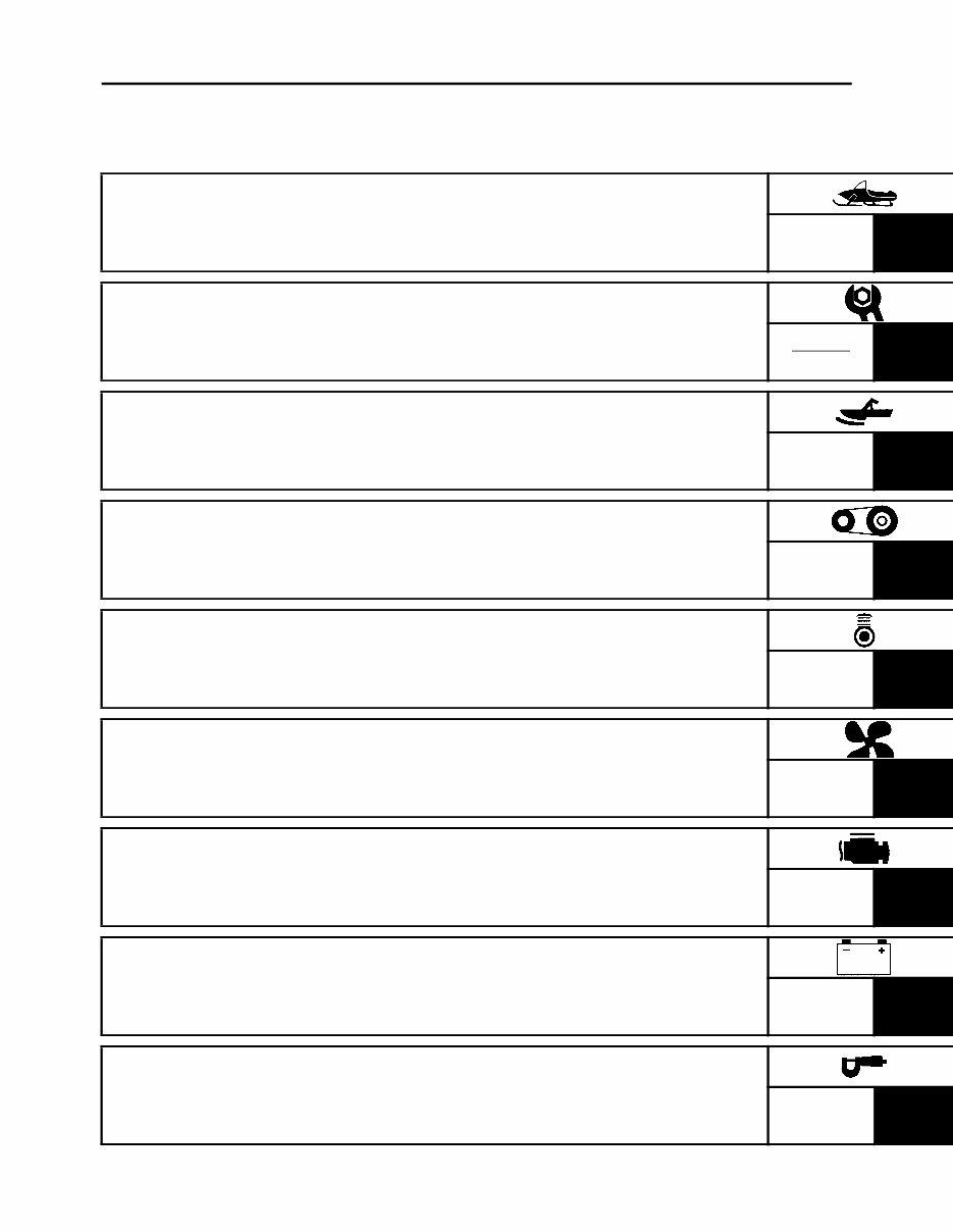
CONTENTS GENERAL INFORMATION GEN INFO 1 PERIODIC INSPECTION AND ADJUSTMENT INSP ADJ 2 CHASSIS CHAS 3 POWER TRAIN POWR TR 4 ENGINE ENG 5 COOLING SYSTEM COOL 6 FUEL INJECTION SYSTEM FI 7 ELECTRICAL ELEC 8 SPECIFICATIONS SPEC 9
CHAPTER 1. GENERAL INFORMATION SNOWMOBILE IDENTIFICATION ............. 1-1 FRAME SERIAL NUMBER .................... 1-1 ENGINE SERIAL NUMBER ................... 1-1 IMPORTANT INFORMATION .................... 1-2 PREPARATION FOR REMOVAL AND DISASSEMBLY...................................... 1-2 REPLACEMENT PARTS ....................... 1-2 GASKETS, OIL SEALS, AND O-RINGS................................................ 1-3 LOCK WASHERS/PLATES AND COTTER PINS ....................................... 1-3 BEARINGS AND OIL SEALS ................ 1-3 CIRCLIPS .............................................. 1-3 LOCTITE® ............................................. 1-3 CHECKING THE CONNECTIONS ........ 1-4 HANDLING THE ELECTRONIC PARTS ................................................... 1-5 SPECIAL TOOLS ....................................... 1-6 FOR TUNE UP....................................... 1-6 FOR ENGINE SERVICE ........................ 1-6 FOR POWER TRAIN SERVICE ............ 1-9 FOR FUEL INJECTION SERVICE ...... 1-10 FOR ELECTRICAL SERVICE ............. 1-10 CHAPTER 2. PERIODIC INSPECTION AND ADJUSTMENT INTRODUCTION......................................... 2-1 PERIODIC MAINTENANCE CHART FOR THE EMISSION CONTROL SYSTEM ..................................................... 2-1 GENERAL MAINTENANCE AND LUBRICATION CHART .............................. 2-1 ENGINE ...................................................... 2-3 SPARK PLUGS ..................................... 2-3 FUEL LINE INSPECTION ..................... 2-4 COOLING SYSTEM .............................. 2-4 VALVE CLEARANCE ADJUSTMENT .................................... 2-10 THROTTLE BODY SYNCHRONIZATION.......................... 2-16 THROTTLE CABLE FREE PLAY ADJUSTMENT .................................... 2-18 THROTTLE OVERRIDE SYSTEM (T.O.R.S.) CHECK............................... 2-19 COMPRESSION PRESSURE MEASUREMENT................................. 2-20 ENGINE OIL LEVEL INSPECTION..... 2-22 ENGINE OIL REPLACEMENT ............ 2-23 CRANKCASE BREATHER HOSE INSPECTION....................................... 2-27 CYLINDER HEAD BREATHER HOSE INSPECTION ........................... 2-27 OIL TANK BREATHER HOSE INSPECTION....................................... 2-28 THROTTLE BODY JOINTS INSPECTION....................................... 2-28 CHECKING THE AIR FILTER ELEMENT............................................ 2-29 EXHAUST SYSTEM INSPECTION..... 2-30 POWER TRAIN ........................................ 2-31 SHEAVE OFFSET ADJUSTMENT...... 2-31 DRIVE V-BELT .................................... 2-33 ENGAGEMENT SPEED CHECK ........ 2-35 PARKING BRAKE PAD INSPECTION....................................... 2-35 PARKING BRAKE ADJUSTMENT ...... 2-36 BRAKE FLUID LEVEL INSPECTION....................................... 2-37 BRAKE PAD INSPECTION ................. 2-38 BRAKE HOSE INSPECTION .............. 2-38 AIR BLEEDING (HYDRAULIC BRAKE SYSTEM) ............................... 2-39 DRIVE CHAIN ..................................... 2-40 TRACK TENSION ADJUSTMENT ...... 2-43 SLIDE RUNNER INSPECTION........... 2-45 EXTROVERT SPROCKET WHEELS (RS90GTZ/RS90LTGTZ) .................... 2-45 MAXIMIZING DRIVE TRACK LIFE ..... 2-46
If you need to perform maintenance or repairs on your 2010-2012 YAMAHA RS VECTOR-VENTURE GT snowmobile, a service repair manual is an essential tool. These manuals contain detailed technical information, diagrams, and instructions to help you troubleshoot, service, and repair your snowmobile.
Whether you are a professional mechanic or a DIY enthusiast, having access to a comprehensive service repair manual can save you time and money by enabling you to perform tasks ranging from basic maintenance to complex repairs.
These manuals are available in .PDF format, providing easy access to the information you need to keep your YAMAHA snowmobile in top condition. With step-by-step procedures and clear, concise language, these manuals are an invaluable resource for anyone working on their snowmobile.
Reviews
Q&A
Recently Viewed
5,521,897Happy Clients
2,594,462eManuals
1,120,453Trusted Sellers
15Years in Business
Price:
Actual Price:
2010-2012 YAMAHA RS VECTOR-VENTURE GT SNOWMOBILE Service REP






 Lifetime Access




