NOTICE This manual was written by the Yamaha Motor Company primarily for use by Yamaha dealers and their qualified mechanics. It is not possible to put an entire mechanic’s education into one manual, so it is assumed that persons using this book to perform maintenance and repairs on Yamaha snowmobiles have a basic understanding of the mechanical con- cepts and procedures inherent in snowmobile repair. Without such knowledge, attempted repairs or service to this model may render it unfit and/or unsafe to use. Yamaha Motor Company, Ltd. is continually striving to improve all models manufac- tured by Yamaha. Modifications and significant changes in specifications or procedures will be for- warded to all authorized Yamaha dealers and will, where applicable, appear in future editions of this manual. HOW TO USE THIS MANUAL Particularly important information is distinguished in this manual by the following notations: The Safety Alert Symbol means ATTENTION! BE ALERT! YOUR SAFETY IS INVOLVED! Failure to follow WARNING instructions could result in severe injury or death to the snowmobile opera- tor, a bystander, or a person inspecting or repairing the snowmobile. A CAUTION indicates special precautions that must be taken to avoid damage to the snowmobile. A NOTE provides key information that can make procedures easier or clearer. MANUAL FORMAT All of the procedures in this manual are organized in a sequential, step-by-step format. The informa- tion has been compiled to provide the mechanic with an easy to read, handy reference that contains comprehensive explanations of all inspection, repair, assembly, and disassembly operations. In this revised format, the condition of a faulty com- ponent will precede an arrow symbol and the course of action required to correct the problem will follow the symbol, e.g., • Bearings Pitting/damage → Replace. EXPLODED DIAGRAM Each chapter provides exploded diagrams before each disassembly section to facilitate correct disas- sembly and assembly procedures. RS90K, RS90RK, RSG90K, RS90MK, RST90K, RST90TFK SERVICE MANUAL P/N.LIT-12618-02-38 WARNING CAUTION: NOTE:
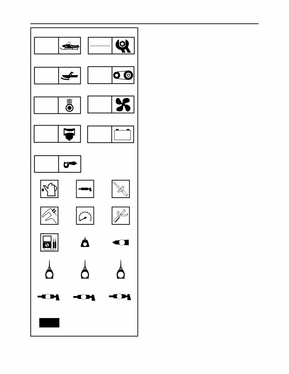
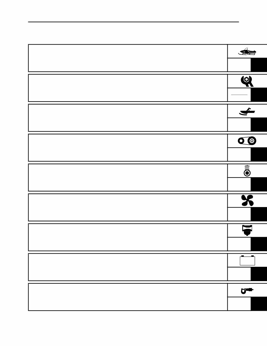
ILLUSTRATED SYMBOLS (Refer to the illustration) Illustrated symbols 1 to 9 are designed as thumb tabs to indicate the chapter’s number and content. 1 General information 2 Periodic inspection and adjustment 3 Chassis 4 Power train 5 Engine 6 Cooling system 7 Carburetion 8 Electrical 9 Specifications Illustrated symbols 0 to F are used to identify the specifications which appear. 0 Filling fluid A Lubricant B Tightening C Wear limit, clearance D Engine speed E Special tool F Ω, V, A Illustrated symbols G to O in the exploded diagram indicate grade of lubricant and location of lubrica- tion point. G Apply locking agent (LOCTITE ® ) H Apply Yamabond No.5 ® I Apply engine oil J Apply gear oil K Apply molybdenum disulfide oil L Apply wheel bearing grease M Apply low-temperature lithium-soap base grease N Apply molybdenum disulfide grease O Use new one 1 2 3 4 5 6 7 8 9 0 A B C D E F G H I J K L M N O GEN INFO INSP ADJ CHAS POWR TR ENG COOL CARB – + ELEC SPEC T R . . LT 5 E G M B LS M New
INDEX GENERAL INFORMATION GEN INFO 1 PERIODIC INSPECTION AND ADJUSTMENT INSP ADJ 2 CHASSIS CHAS 3 POWER TRAIN POWR TR 4 ENGINE ENG 5 COOLING SYSTEM COOL 6 CARBURETION CARB 7 ELECTRICAL ELEC 8 SPECIFICATIONS SPEC 9 – +
CHAPTER 1. GENERAL INFORMATION MACHINE IDENTIFICATION............................ 1-1 FRAME SERIAL NUMBER ......................... 1-1 ENGINE SERIAL NUMBER ........................ 1-1 IMPORTANT INFORMATION .......................... 1-2 PREPARATION FOR REMOVAL AND DISASSEMBLY........................................... 1-2 ALL REPLACEMENT PARTS..................... 1-2 GASKETS, OIL SEALS, AND O-RINGS..... 1-3 LOCK WASHERS/PLATES AND COTTER PINS ................................... 1-3 BEARINGS AND OIL SEALS ..................... 1-3 CIRCLIPS ................................................... 1-3 LOCTITE ® .................................................. 1-3 SPECIAL TOOLS ............................................. 1-4 FOR TUNE UP............................................ 1-4 FOR ENGINE SERVICE ............................. 1-4 FOR POWER TRAIN SERVICE ................. 1-7 FOR CARBURETION SERVICE ................ 1-8 FOR ELECTRICAL SERVICE .................... 1-8 CHAPTER 2. PERIODIC INSPECTION AND ADJUSTMENT INTRODUCTION............................................... 2-1 PERIODIC MAINTENANCE CHART................ 2-1 ENGINE ............................................................ 2-3 SPARK PLUGS........................................... 2-3 FUEL LINE INSPECTION ........................... 2-3 COOLING SYSTEM.................................... 2-4 VALVE CLEARANCE ADJUSTMENT ........ 2-7 CARBURETOR SYNCHRONIZATION ..... 2-13 ENGINE IDLE SPEED ADJUSTMENT ..... 2-14 THROTTLE CABLE FREE PLAY ADJUSTMENT .......................................... 2-15 THROTTLE OVERRIDE SYSTEM (T.O.R.S.) CHECK .................................... 2-16 COMPRESSION PRESSURE MEASUREMENT ...................................... 2-17 ENGINE OIL LEVEL INSPECTION .......... 2-18 ENGINE OIL REPLACEMENT ................. 2-20 CRANKCASE BREATHER HOSE INSPECTION ............................................ 2-23 CARBURETOR JOINTS INSPECTION .... 2-23 CHECKING THE AIR FILTER ELEMENT ................................................. 2-23 EXHAUST SYSTEM INSPECTION .......... 2-24 POWER TRAIN............................................... 2-25 SHEAVE OFFSET ADJUSTMENT ........... 2-25 DRIVE V-BELT.......................................... 2-27 ENGAGEMENT SPEED CHECK .............. 2-29 PARKING BRAKE ADJUSTMENT............ 2-30 BRAKE FLUID LEVEL INSPECTION ....... 2-30 BRAKE PAD INSPECTION....................... 2-31 BRAKE HOSE INSPECTION .................... 2-31 AIR BLEEDING (HYDRAULIC BRAKE SYSTEM) .................................................. 2-32 DRIVE CHAIN ........................................... 2-33 TRACK TENSION ADJUSTMENT ............ 2-35 SLIDE RUNNER INSPECTION ................ 2-37 MAXIMIZING DRIVE TRACK LIFE ........... 2-37 CHASSIS ........................................................ 2-39 SKI/SKI RUNNER ..................................... 2-39 STEERING SYSTEM ................................ 2-40 LUBRICATION .......................................... 2-41 ELECTRICAL ................................................. 2-44 HEADLIGHT BEAM ADJUSTMENT ......... 2-44 BATTERY INSPECTION........................... 2-44 FUSE INSPECTION.................................. 2-52 SPEEDOMETER UNIT INSPECTION ...... 2-54 TUNING .......................................................... 2-55 CARBURETOR TUNING .......................... 2-55 CLUTCH.................................................... 2-62 GEAR SELECTION................................... 2-67 HIGH ALTITUDE TUNING ........................ 2-73 FRONT SUSPENSION ............................. 2-74 REAR SUSPENSION................................ 2-75 CHAPTER 3. CHASSIS STEERING ........................................................ 3-1 RS90/RS90R/RSG90/RST90/RST90TF ..... 3-1 RS90M ........................................................ 3-3 REMOVAL................................................... 3-7 INSPECTION .............................................. 3-7 INSTALLATION........................................... 3-8 SKI .................................................................. 3-12 RS90/RS90R/RSG90 “USA/Canada” ....... 3-12 RSG90 “Europe”/RST90 “Europe”/ RST90TF................................................... 3-13 RS90M ...................................................... 3-14 RST90 “USA/Canada”............................... 3-15 INSPECTION ............................................ 3-16 INSTALLATION (RST90 “USA/Canada”) ............................ 3-17
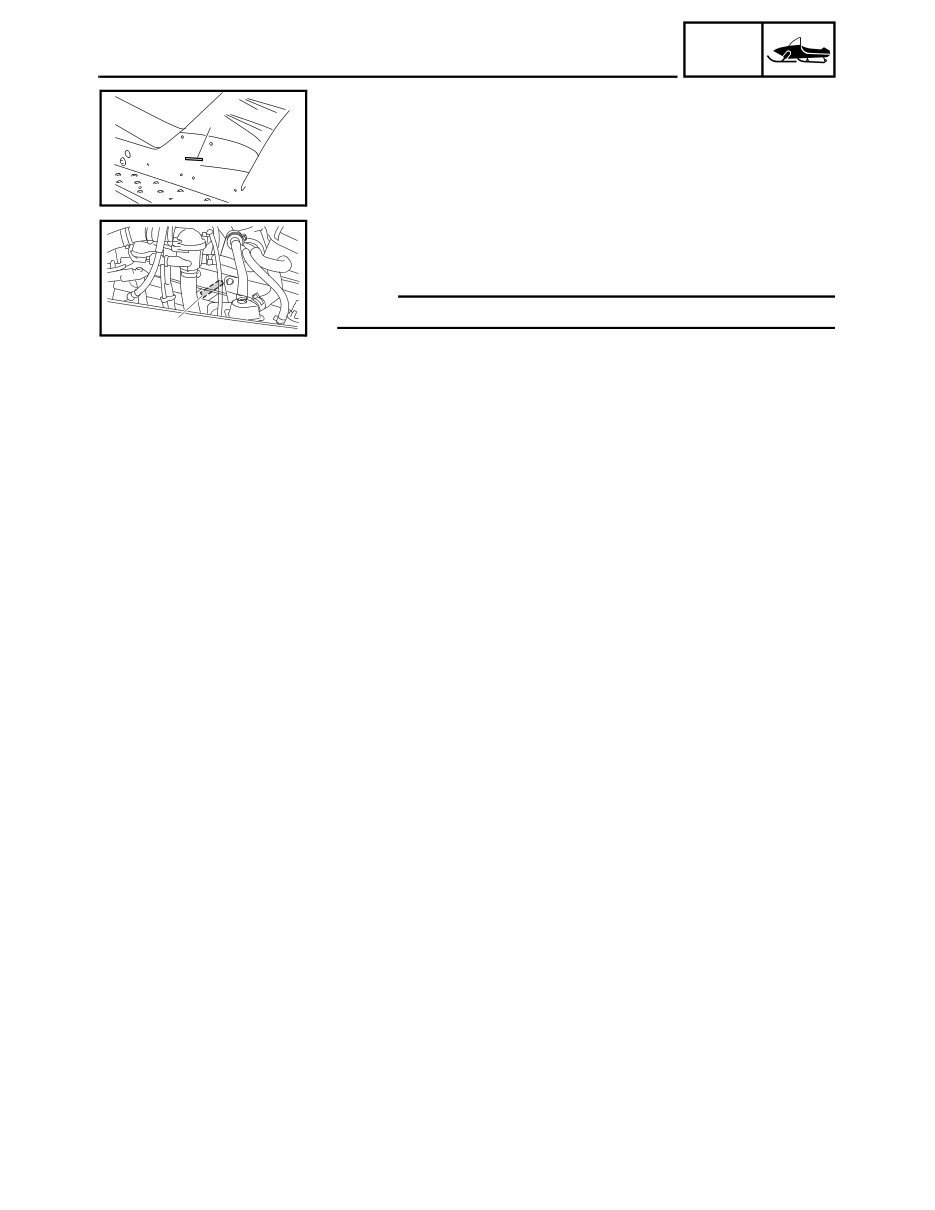
1-1 GEN INFO GENERAL INFORMATION MACHINE IDENTIFICATION FRAME SERIAL NUMBER The frame serial number 1 is located on the right-hand side of the frame (just below the front of the seat). 1 ENGINE SERIAL NUMBER The engine serial number 1 is located on the right-hand side of the crank- case. NOTE: Designs and specifications are subject to change without notice. 1 MACHINE IDENTIFICATION
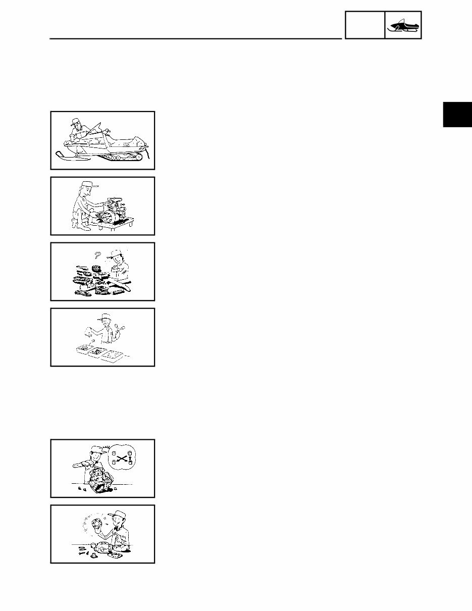
1-2 GEN INFO IMPORTANT INFORMATION IMPORTANT INFORMATION PREPARATION FOR REMOVAL AND DISASSEMBLY 1.Remove all dirt, mud, dust, and foreign material before removal and disassembly. While cleaning, take care to protect the electrical parts, such as relays, switches, motor, resistors, controllers, etc., from high pressure water splashes. 2. Use proper tools and cleaning equipment. Refer to “SPECIAL TOOLS”. 3.When disassembling the machine, keep mated parts together. This includes gears, cylinders, pistons, and other parts that have been “mated” through normal wear. Mated parts must be reused or replaced as an assembly. 4. During disassembly of the machine, clean all parts and place them in trays in the order of disassembly. This will speed up assembly time and help ensure that all parts are reinstalled correctly. 5.Keep all parts away from any source of fire. 6.Be sure to keep to the tightening torque specifications. When tighten- ing bolts, nuts, and screws, start with those that have larger diameters, and proceed from the inside to the outside in a crisscross pattern. ALL REPLACEMENT PARTS We recommend using genuine Yamaha parts for all replacements. Use oil and grease recommended by Yamaha for assembly and adjustments. 1
You're Reading a Preview
What's Included?
Lifetime Access
Fast Download Speeds
Online & Offline Access
Access PDF Contents & Bookmarks
Full Search Facility
Print one or all pages of your manual
$39.99
2007 YAMAHA RS VENTURE Factory Service & Work Shop Manual
Upon purchasing this manual, you will receive a .PDF file containing an email contact. After contacting us, you will receive a reply with a link to access the manual for your 2007 YAMAHA RS VENTURE.
This comprehensive manual covers every aspect of your machine, providing detailed instructions for tasks ranging from simple maintenance, such as an oil change, to more complex procedures like a transmission swap. With hundreds of pages, it includes numerous illustrations to assist you and easy-to-understand text throughout.
The manual features a search function, allowing you to easily navigate and print the necessary pages. It serves as a Factory Service Repair Manual, offering step-by-step guidance on maintenance and repair fundamentals, providing the same knowledge that factory-trained technicians possess.
By utilizing the information within this service repair manual, both professional mechanics and DIY enthusiasts can confidently make informed decisions regarding the maintenance and repair of their machine.
Our commitment extends beyond providing a high-quality service manual; we also ensure excellent customer service, guaranteeing your satisfaction.
Reviews
Q&A
Recently Viewed
5,521,897Happy Clients
2,594,462eManuals
1,120,453Trusted Sellers
15Years in Business
Price:
Actual Price:
2007 YAMAHA RS VENTURE Factory Service & Work Shop Manual








 Lifetime Access




