CONTENTS 1. MODIFiCATIONS 2 2. NEW SERVICE PROCEDURE 5 3. MAINTENANCE INTERVALS 6 4. SPECiFiCATIONS 8 5. SPECIAL TOOLS : 14 6. WIRING DIAGRAM 15 7. WIRE AND PIPE ROUTING DIAGRAM 17 -1- 1980 EX440
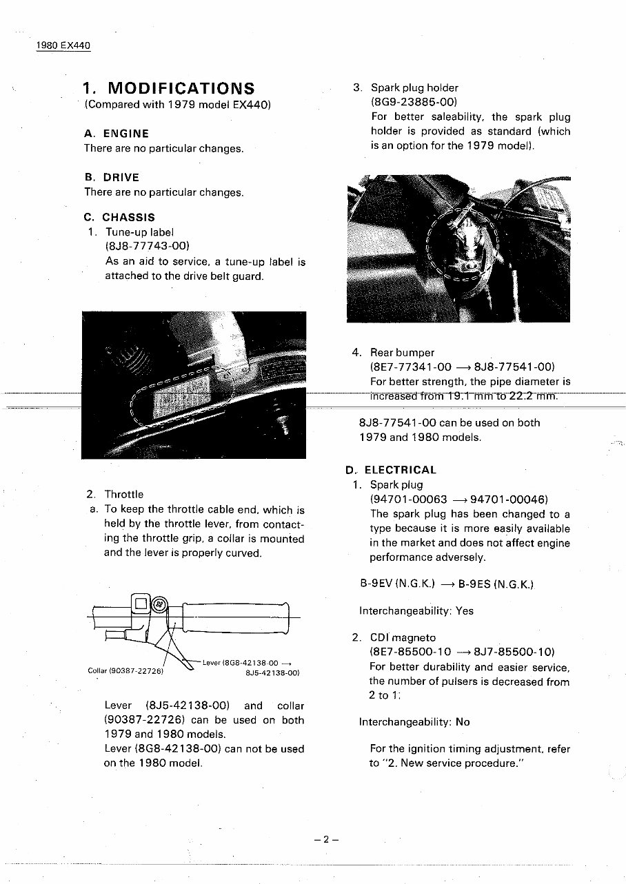
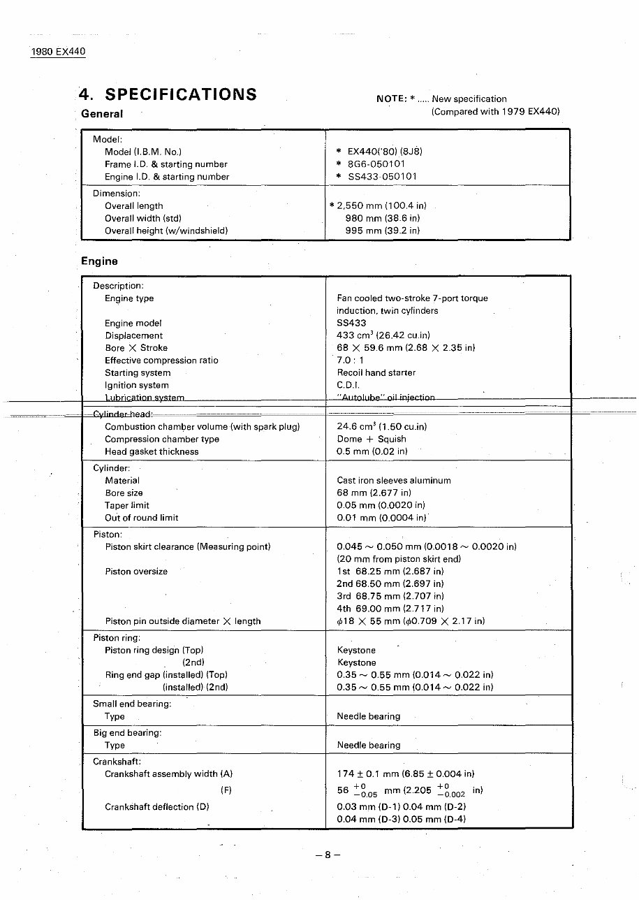
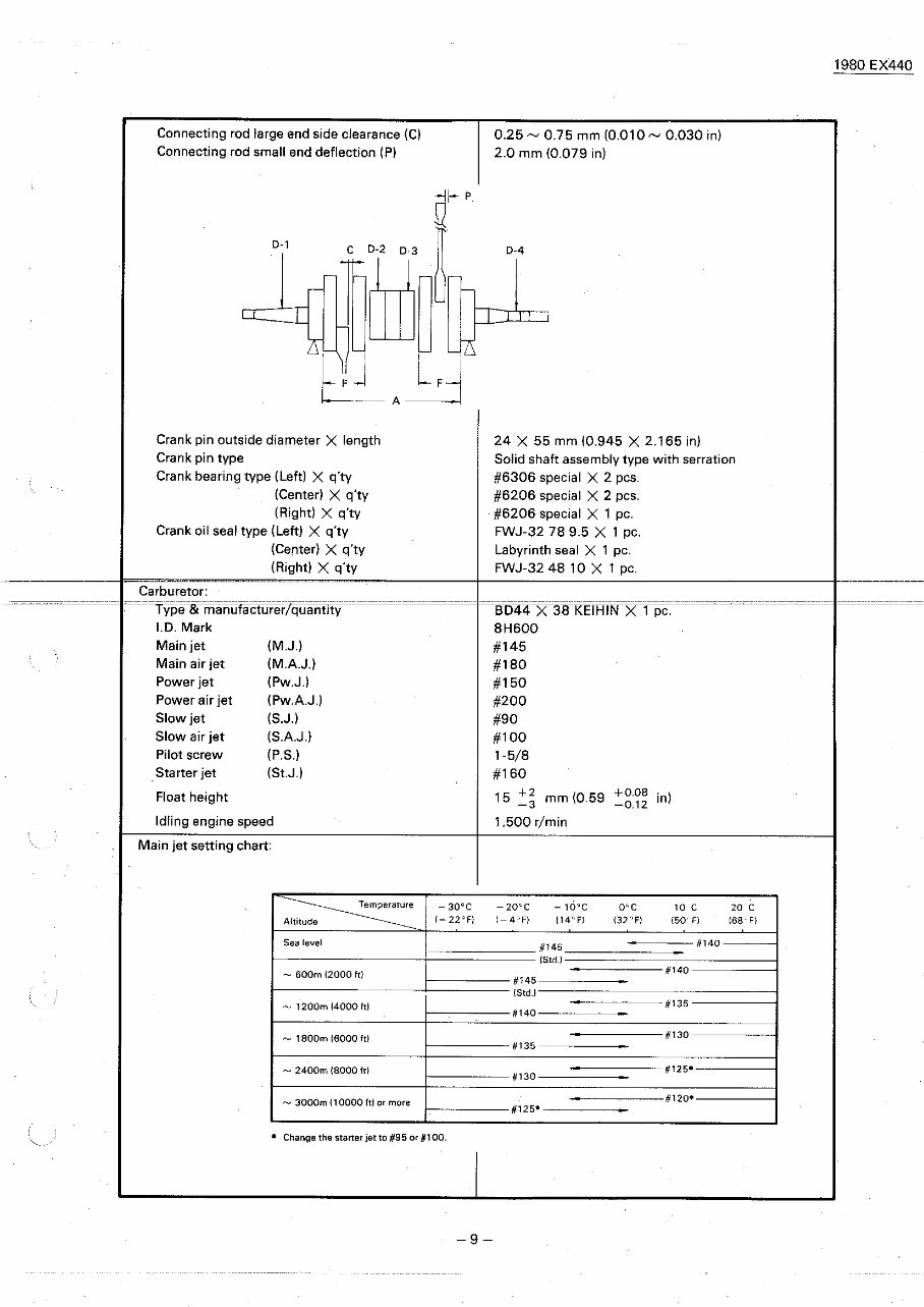
1980 EX440 1. MODIFICATIONS (Compared with 1979 model EX440) A. ENGINE There are no particular changes. B. DRIVE There are no particular changes. C. CHASSIS 1. Tune-up label (8J8-777 43-00) As an aid to service. a tune-up label is attached to the drive belt guard. 2. Throttle a. To keep the throttle cable end, which is held by the throttle lever, from contact- ing the throttle grip, a collar is mounted and the lever is properly curved. 3. Spark plug holder (8G9-23885-00) For better saleability. the spark plug holder is provided as standard (which is an option for the 1979 model). 4. Rear bumper (8E7-77341-00 ----> 8J8-77541-00) For better strength, the pipe diameter is rncrease rom . mm 0 . mm. 8J8-77 541 -00 can be used on both 1979 and 1980 models. D. ELECTRICAL 1. Spark plug (94701-00063 ----> 94701-00046) The spark plug has been changed to a type because it is more easily available in the market and does not affect engine performance adversely. B-9EV (N.G.K.) ----> B-9ES (N.G.K.) Lever (8J5-42138-00) and collar (90387-22726) can be used on both 1979 and 1980 models. Lever (8G8-42138-00) can not be used on the 1980 model. Collar (90387-22726l Lever (8GB-42138-00 ----+ BJ5-42138-00) -2- Interchangeability: Yes 2. COl magneto (8E7-85500-10 ----> 8J7-85500-1 0) For better durability and easier service, the number of pulsers is decreased from 2 to 1: Interchangeability: No For the ignition timing adjustment. refer to "2. New service procedure."
1980 EX440 3. COl unit (8H6-85540-10 -+ 8J7-85540-10) Due to change in the COl magneto. the circuit is modified. Interchangeability: No 4. Main switch (898-82508-20 -+ BJ7 -82508-20) For better safety, the circuits of the headlight, meter light and taillight are modified so that they are turned on as long as the engine is in operation, and their positions are changed. '79 model '80 model Gray \ Lead wire I"'" Lead wire color Gray Orange Red/Blue Blue/White Red/White Blue cclor Black Black/White Position '\. ¢ Position -"" OFF OFF ON ON/LIGHT LIGHT ~BraCk oran\8 . II -. VI- d IS Black/White >...\... 0 0 II II Blue __ ~T I Red/Blue Bfue/White Interchangeability: No 5. Wire harness For better safety, the circuits are modified so that the headlight, meter light and taillight are turned on, when- ever the engine runs. (Refer to "6. Wir- ing Diagram.") Wire harness ass'v: 8G6-82590-20 -+ 8J7 -82590-20 Wire harness ass'v 2: 8G6-82580-20 -+ 8J7-82580-20 Interchangeability: No -3-
1980 EX440 6. Tether switch (S9S-S2550-00 ---> SJ7-S2550-00) To prevent the switch from coming off easily, the rubber cap thickness is in- 79 model creased, by which the durability and strength of the cap is also increased. The ring is provided with a hook so it can easily be hooked to the clothes. 'SO model Increased thickness E Interchangeability: Yes 7. Headlight unit (SE7-S4310-40 --->SH7-S4310-41) The headlight is modified so that it meets the European regulations. -4- Hook is added 12V 60/60W ---> 12V 45/40W . Interchangeability: No
1980 EX440 3. Insert the dial gauge with needle into the stand. Tool name Tool No. Dial gauge 90890-01252 Dial gauge needle 90890-03098 2. NEW SERVICE PROCEDURE (New service procedure applied to the 1980 EX440) If not aligned. adjust ignition timing as follows: Ignition timing (B.T.D.C.) 1.6 ± 0.1 mm (0.060 ± 0.004 in) 7. Check the marks on flywheel and pulser for alignment. Tool No. 90890-01195 Tool name Dial gauge stand Ignition timing 1. Remove the recoil starter assembly. 2. Remove the right side spark plug and screw the dial gauge stand into the spark plug hole. 4. Rotate the magneto flywheel unit piston is at top-dead-center (T.D.C.) Set the zero on dial gauge face to line up exactly with a dial gauge needle. Tighten the set screw on the dial gauge stand to secure the dial gauge assemb- ly. Rotate the flywheel back and forth to be sure that the indicator needle does not go past zero. 5. Starting at T.D.C., rotate the flywheel counterclockwise until the dial gauge reads approximately 3-1/2 needle re- volutions before-top-dead -cente r (B.T.D.C.). 6. Slowly turn the flywheel clockwise until the dial guage reads specified ignition timing. a. Loosen the pulser set screws and turn achieved. NOTE: --------------' If the marks can not be aligned by this ad- justment. remove the flywheel rotor and turn the base (stator) assembly. -5-
1980 EX440 b. Tighten the pulser set screws. 8. Remove the dial gauge and stand. Re- place the spark plug and recoil starter. Tightening torque Spark plug: 28 Nm (2.8 rn-kq. 20 ft-lb) , Starter assembly: 7 Nm (0.7 m-kq, 5 ft-lb) 3. MAINTENANCE INTERVAL [PERIODIC MAINTENANCE] NOTE: ------------ The timing light should be used to check if the marks on the rotor and base are aligned when both are replaced with new ones. the marks should align at any specified timing. Every 20 hrs. or 40 hrs. or 80 hrs.or When I Check point Seasonally 400km BOO km 1.600 km necessary {250mi} (500mi) (1.000 mil ENGINE: Tightness of bolts and nuts a a Bends. cracks and wear a a Loose-connection and-break f ,.. Loose connection and breaks of oil pipes a a Loose connection and breaks of oil delivery pipe a a Manual rope starter system a . a Carburetor . • Operation of starter jet a a • Mixing adjuster (pilot screw) a a • Idlil)g speed adjustment a a Operation and adjustment of oil pump a a Ignition timing .a Cylinder compressions a a Muffler joints a a Cylinder head/exhaust pipe decarbonize a Spark plug condition, gap and clea-ning a a Tightening of the cylinder head .... a DRIVE: Tightness of bolts and nuts a a Wear on slide runners a a Primary drive system a . a V-belt a a Secondary drive system a a Sheave distance a a Sheave offset a a Brake pad wear a a Brake operation and adjustment a a Guide wheel rubber a a Wear of drive track wheel sprocket a a Drive track adjustment a a Breaks in drive track a a Bends in front and rear axles a a Checking of lock washers a a Drive chain adjustment a a Drive chain oil level a a -6-
1980 EX440 Every Check point 20 hrs. or 40 hrs. or 80 hrs. or When Seasonally 4QOkm 800km 1.600 km necessary (250 mil (500 mil (1,000 mil BODY: Tightness o~ bolts and nuts 0 0 Bends and cracks 0 0 Welded riveted, joints 0 0 Ski adjustment 0 0 Ski runner wear 0 0 Breaks in fuel tank 0 0 Cleaning of fuel tank 0 Fuel filter 0 Loose connection and breaks in fuel pipe 0 0 Breaks in oil tank 0 0 Oil filter 0 ELECTRICAl: Wear, breakage of wire covering 0 0 Breaks in high-tension cord 0 0 Voltage regulator working voltage 0 Operation of engine stop switch 0 0 Operation of tether switch 0 0 Headlight 0 0 Taillight 0 0 Brake light 0 0 •• ReLigliteli eve,y 16 !lOUiS fiUllitlie fiiSl ase. [LUBRICATION INTERVALS] Every Lubrication point 20 hrs. or 40 hrs. or 80 hrs. or when Seasonally Oil/Grease 400km BOOkm 1.6'00 km necessary Brand name (250 mt} (500 mil (1.000 mil ENGINE: Starter case 0 Oil pump control box 0 0 Aeroshell grease #7A or Esso Beacon 325 grease Pump drive cover 0 0 Oil in the oil tank 0 YAMALUBE 2-cycle oil DRIVE: Primary sheave weight 0 0 and roller pins Molybdenum disulfide Secondary shaft and 0 0 snowmobile grease sliding sheave Front axle housing 0 0 Shaft 1 and shaft 2 0 0 Light all-purpose grease (Slide rail) Drive chain oil 0 0 Gear oil API "GL-3" replacement SAE #75 or #BO BODY: Steering column lower 0 0 Light all-purpose grease bearing Steering column upper 0 0 Motor oil bearing . Steering links 0 0 Ski column 0 0 Ski wear plate 0 0 light all-purpose grease Ski retaining pin 0 0 Brake wire and stopper 0 0 Esso Beacon 325 grease and brake lever -7-
1980 EX440 4. SPECIFICATIONS General NOTE: * ..... New specification (Compared with 1979 EX440) Model: Model (I.B.M. No.l * EX4401'BO)18J8) Frame 1.0. & starting number * BG6-050101 Engine 1.0. & starting number * 55433-050101 Dimension: Overall length * 2,550 mm (100.4 in) Overall width (std) 980 mm (38.6 in) Overall height (w/windshield) 995 mm (39.2 in) Engine Description: En~ine type Fan cooled two-stroke 7-port torque induction. twin cylinders Engine model 55433 Displacement 433 em' (26.42 eu.in) Bore X Stroke 68 X 59.6 mm (2.68 X 2.35 in) Effective compression ratio 7.0: 1 Starting system Recoil hand starter Ignition system C.D.1. , "A, -" " ,A, Combustion chamber volume {with spark plug) 24.6 em' (1.50 eu.in) Compression chamber type Dome + Squish Head gasket thickness 0.5 mm (0.02 in) . Cylinder: Material Cast iron sleeves aluminum Bore size 68 mm (2.677 in) Taper limit 0.05 mm (0.0020 in) Out of round limit 0.01 mm (0.0004 in) Piston: . Piston skirt clearance (Measuring point) 0.045 ~ 0.050 mm (0.0018 ~ 0.0020 in) (20 mm from piston skirt end) Piston oversize 1st 68.25 mm 12.687 in) 2nd 6B.50 mm 12.697 in) 3rd 68.75 mm 12.707 in) 4th 69.00 mm (2.717 in) Piston pin outside diameter X length ,p18 X 55 mm (,p0.709 X 2.17 in) Piston ring: Piston ring design (Top) Keystone (2nd) Keystone Ring end gap Iinstalledl I'Fop) 0.35 ~ 0.55 mm (0.014~ 0.022 in) (installed) (2nd) 0.35 ~ 0.55 mm (0.014 ~ 0.022 in) Small end bearing: Type Needle bearing Big end bearing: Type Needle bearing Crankshaft: Crankshaft assembly width (A) 174 ± 0.1 mm (6.85 ± 0.004 in) IF) +0 ( +0 in) 56 -0.05 mm 2.205 -0.002 Crankshaft deflection (D) 0.03 mm (D-1) 0.04 mm (D-2) 0.04 mm (D-3) 0.05 mm (D-4) -8-
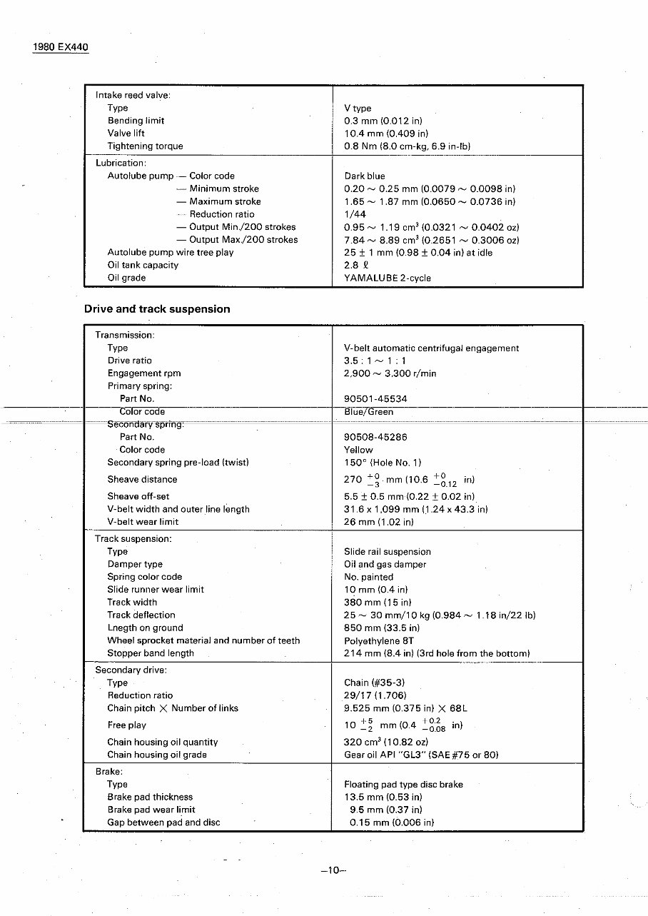
Connecting rod large end side clearance (C) Connecting rod small end deflection (PI 0.25 - 0.75 mm 10.010 - 0.030 in) 2.0 mm (0.079 in) 1980 EX440 r DA I (M.J.) (MAJ.) (Pw.J.) (PwAJ.) IS.J.) ISAJ.) (P.S.) (St.J.) Crank pin outside diameter X length Crank pin type Crank bearing type (Left) X q'tv (Center) X q'tv IRight) X q'tv Crank oil seal type ILeft) X q'tv (Center) X q'tv (Right) X q'tv Carburetor: I"y"eBl'manUTaciurerTquantlty I.D. Mark Main jet Main air jet Power jet Power air jet Slow jet Slow air jet Pilot screw Starter jet Float height Idling engine speed Main jet setting chart: 24 X 55 mm (0.945 X 2.165 in) Solid shaft assembly type with serration #6306 special X 2 pes. #6206 special X 2 pcs. #6206 special X 1 pc. FWJ-32 78 9.5 X 1 pc. Labyrinth seal X 1 pc. FWJ-32 48 10 X 1 pc. 8D44 X 38 KEIHIN X 1 pc. 8H500 #145 #180 #150 #200 #90 #100 1-5/8 #150 15 +2 mm 10.59 +0.08 in) -3 -0.12 1.500 r/min __________ Tempe;~;~re Altitude ______________ Sea level - 30°C (-22°Fl -czo-c 1-4"F) '0 C (50' F) #140 20e 168'- F) - 600m (2000 Itl -- 1200m (4000 ft) - , 800m (6000 ft) -- 2400m (8000 ftl -- 3000m (10000 ftl or more • Change the starter jet to #95 or /,1100. #140 #135 #130 /,/135 #130 #125· -9-
1980 EX440 Intake reed valve: Type V type Bending limit 0.3 mm 10.012 in) Valve lift lOA mm IOA09 in) Tightening torque 0.8 Nm 18.0 cm-kq. 6.9 in-Ib) Lubrication: Autolube pump - Color code Dark blue - Minimum stroke 0.20 ~ 0.25 mm 10.0079 ~ 0.0098 in] - Maximum stroke 1.65 ~ 1.87 mm 10.0650 ~ 0.0736 inl - Reduction ratio 1/44 - Output Min./200 strokes 0.95 ~ 1.19 em' (0.0321 ~ 0.0402 oz) - Output Max./200 strokes 7.84 ~ 8.89 em' (0.2651 ~ 0.3006 oz] Autolube pump wire tree play 25 ± 1 mm (0.98 ± 0.04 inlat idle Oil tank capacity 2.8 Q Oil grade YAMAlUBE 2-eyele Drive and track suspension Transmission: Type V-belt automatic centrifugal engagement Drive ratio 3.5: 1 ~ 1:1 Engagement rpm 2,900 ~ 3,300 r/min Primary spring: Part No. 90501-45534 Color code Blue/Green ___________ 0_- . ,~",,~. Part No. 90508-45286 Color code Yellow Secondary spring pre-load (twist) 150 0 (Hole No. 11 Sheave distance 270 +0 mm 110.6 +0 in) -3 -0.12 Sheave off-set 5.5 ± 0.5 mm 10.22 ± 0.02 inl V-belt width and outer line length 31.6 x 1,099 mm (1.24 x 43.3 in) V-belt wear limit 26 mm 11.02 in) Track suspension: Type Slide rail suspension Damper type Oil and gas damper Spring color code No. painted Slide runner wear limit 10 mm lOA in) Track width 380 mm 115 inl Track deflection 25 ~ 30 mm/1 0 kg 10.984 ~ 1.18 in/22 lb) Lnegth on ground 850 mm (33.5 in) Wheel sprocket material and number of teeth Polyethylene BT Stopper band lenqth 214 mm (8.4 inl 13rd hole from the bottom I Secondary drive: Type Chain (#35-3) Reduction ratio 29/17 (1.706) Chain pitch X Number of links 9.525 mm 10.375 in) X 68l Free play 10 +5 104 +0.2 in) -2 mm . -0.08 Chain housing oil quantity 320 em' (10.82 oz] Chain housing oil grade Gear oil API "Gl3" ISAE #75 or 80) Brake: Type Floating pad type disc brake Brake pad thickness 13.5 mm (0.53 in) Brake pad wear limit 9.5 mm (0.37 in) Gap between pad and disc 0.15 mm (0.006 in) -10-
MyGreenManuals.com is your number one source for repair manuals. Our informative repair manuals, owner's manuals, and parts catalogs contain all the information you'll need to perform repairs, look up parts, or do routine maintenance on your machine. You will have access to information regarding the following topics:
General Information
Routine Maintenance
Engine Removal and Installation
Fuel System
Lubrication and Cooling System
Engine Specifications
Transmission, Drive Chain & Sprockets
Steering System
Shocks
Body Work
Intake & Exhaust
Electrical System
Advanced Troubleshooting
And much more! With our repair manuals, find the page pertaining to your job, print it off, and get working on your machine. No more ruining your expensive paper shop manual with grease and dirt.
Broke down on the trail or site and have a smartphone? What a cool way to find your problem and repair it on the trail, no downtime on the job site. With our repair manuals, you instantly have access to the material needed to get you running again. Kind of tough to do that with a paper manual.
And did we mention the fact that you're saving the trees? All our repair manuals come with a lifetime protection policy. If lost or damaged, simply contact us, and we'll replace it free of charge for life.
We provide various repair service manuals, workshop manuals, repair manuals, owners manuals, parts catalogs, and other various manuals, all in an electronic format.
UTVs, motorcycles, ATVs, quads, snowmobiles, Seadoo, equipment, small engines, inboards, outboards, and more.
Instant Access
No Shipping Cost
Get a Download So No Waiting, Repair It Now
If you are looking for a specific manual and cannot find it or do not see it listed, then contact our customer support team via the contact us link above with details of the required manual, and we will do our absolute best to find and list it for you.