2012 Ski-Doo REV XP 600, 600 HO E-TEC, 800R Power TEK & 800R E-TEC Series 2012 Ski-Doo REV XR 600 HO E-TEC & 800R E-TEC Series This manual may cover later years than listed above. If you bought this manual from any other seller, they are reselling my work. Please leave them negative feedback & email me at bestshopmanuals@gmail.com . Our goal is to be one of the BEST sellers on eBay and the internet by providing you with the BEST customer service and the BEST manuals on the market. Thank you for choosing us.
SAFETY NOTICE SAFETY NOTICE This manual has been prepared as a guide to cor- rectly service and repair 2012 Ski-Doo ® snowmo- biles described in the list in the INTRODUCTION. This edition was primarily published to be used by technicians who are already familiar with service procedures relating to Bombardier Recreational Products Inc. (BRP) products. Mechanical tech- nicians should attend continuous training courses given by BRPTI. Please note that the instructions will apply only if proper hand tools and special service tools are used. The content of this manual depicts parts and/or procedures applicable to a particular product at time of writing. Service and Warranty Bulletins may be published to update the content of this manual. Dealer modifications that were carried out after manufacturing of the product, wether or not authorized by BRP, are not included. In addition, the sole purpose of the illustrations throughout the manual, is to assist identification of the general configuration of the parts. They are not to be interpreted as technical drawings or ex- act replicas of the parts. The use of BRP parts is most strongly recom- mended when considering replacement of any component. Dealer and/or distributor assistance should be sought in case of doubt. The engines and the corresponding components identified in this document should not be utilized on product(s) other than those mentioned in this document. It is understood that certain modifications may render use of the vehicle illegal under existing federal, provincial and state regulations. This manual emphasizes particular information de- noted by the wording and symbols: WARNING Indicates a potential hazard that, if not avoided, could result in serious injury or death. CAUTION Indicates a hazardous situation which, if not avoided, could result in minor or moderate injury. NOTICE Denotes an instruction which, if not followed, could severely damage vehicle com- ponents. NOTE: Indicates supplementary information needed to fully complete an instruction. Although the mere reading of such information does not eliminate the hazard, your understand- ing of the information provided will promote its correct use. Always use common shop safety practice. It is understood that this manual may be trans- lated into another language. In the event of any discrepancy, the English version shall prevail. BRP disclaims liability for all damages and/or in- juries resulting from the improper use of the con- tents. Unless otherwise indicated, engine must be OFF and tether cord removed prior to perform any ser- vices. We strongly recommend that any services be car- ried out and/or verified by a highly skilled profes- sional mechanic.
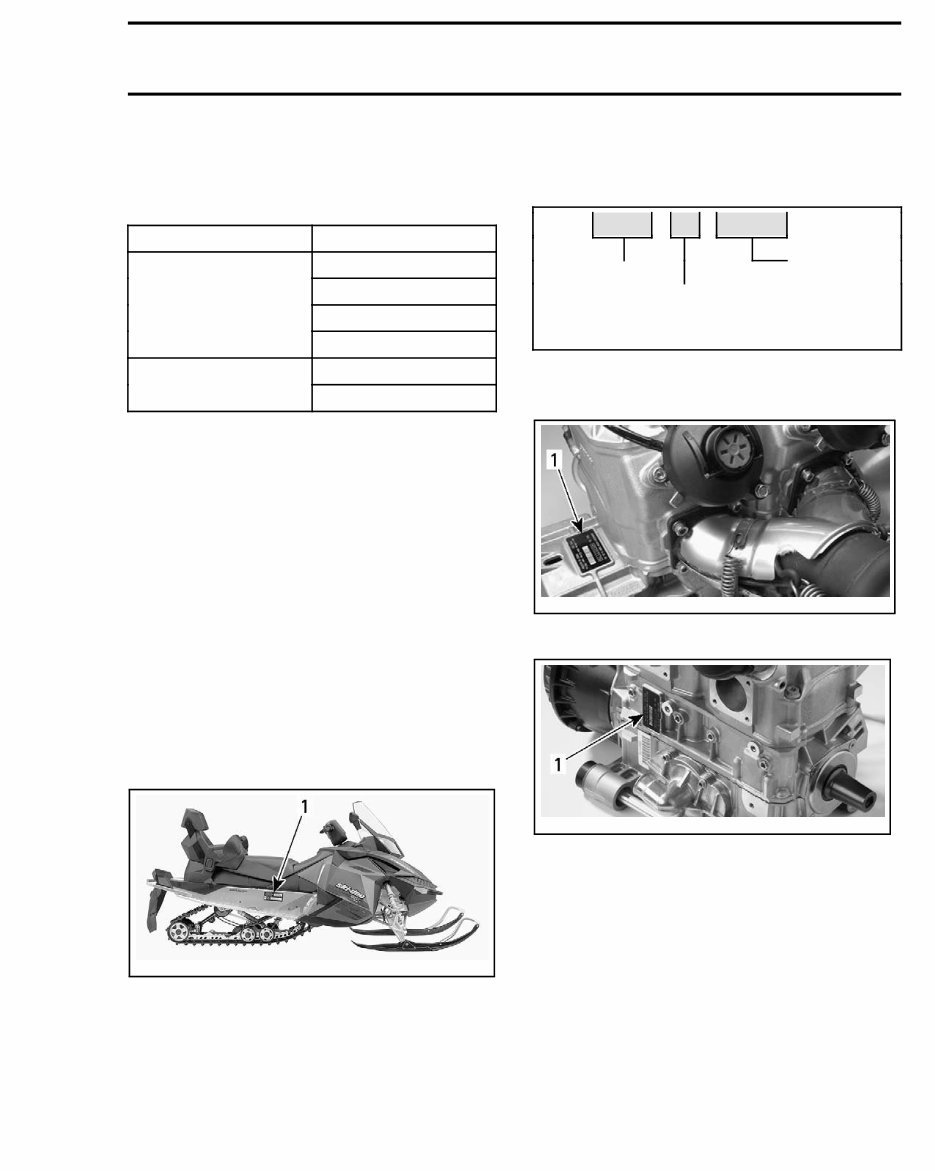
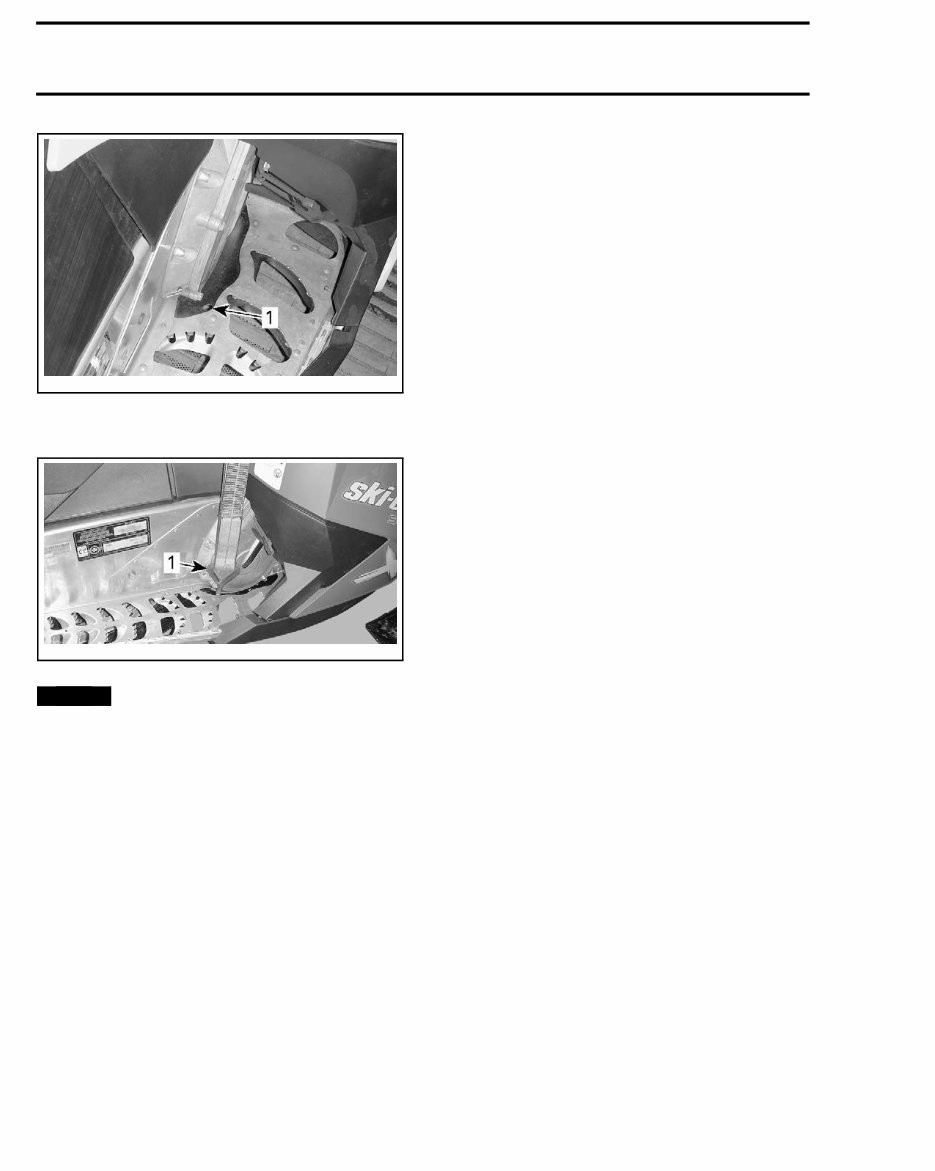
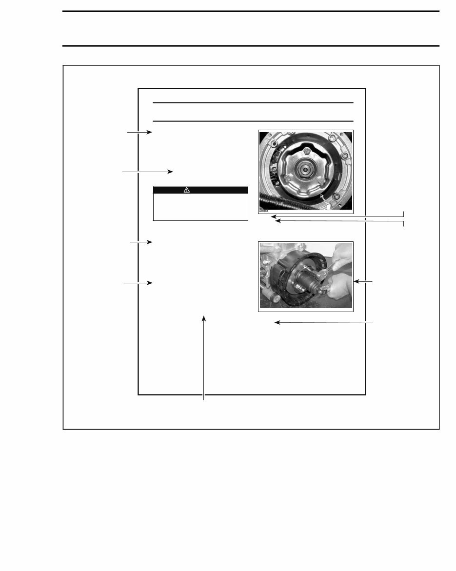
INTRODUCTION INTRODUCTION This Shop Manual covers the following BRP made 2012 snowmobiles: CHASSIS ENGINE 600 600 HO E-TEC ® 800R Power TEK™ REV-XP™ 800R E-TEC 600 HO E-TEC REV-XR™ 800R E-TEC The information and component/system descrip- tions contained in this manual are correct at time of writing. BRP however, maintains a policy of continuous improvement of its products without imposing upon itself any obligation to install them on products previously manufactured. Due to late changes, there may be some differ- ences between the manufactured product and the description and/or specifications in this document. BRP reserves the right at any time to discontinue or change specifications, designs, features, mod- els or equipment without incurring obligation. VEHICLE INFORMATION VEHICLE IDENTIFICATION NUMBER (VIN) mmo2008-003-008_a TYPICAL 1. Vehicle identification number Identification Number Description 2BPS LSAB 9 A 1 000001 Model number Serial number Model year: A = 2010 B = 2011 C = 2012 etc. ENGINE SERIAL NUMBER mmo2007-002-007_a TYPICAL — 600 AND 600 HO E-TEC ENGINES 1. Engine serial number mmo2007-002-006_a TYPICAL — 800R POWER TEK AND 800R E-TEC ENGINES 1. Engine serial number SNOWMOBILE LIFTING To lift the snowmobile securely, it is important to use the reinforced footrest holes.
INTRODUCTION mmr2008-002-100_a 1. Reinforced holes in footrest Install lifting tool hooks in holes as shown. mmr2008-002-101_a 1. Hook of lifting tool NOTICE Do not use footrest opening or steer- ing column to lift the snowmobile. Frame or steering system could be seriously damaged. ENGINE EMISSIONS INFORMATION Manufacturer's Responsibility Manufacturers of engines must determine the exhaust emission levels for each engine horse- power family and certify these engines with the United States of America ENVIRONMENTAL PROTECTION AGENCY (EPA). An emissions con- trol information label, showing emission levels and engine specifications, must be placed on each vehicle at the time of manufacture. Dealer Responsibility When servicing any snowmobile that carries an emissions control information label, adjustments must be kept within published factory specifica- tions. Replacement or repair of any emission related component must be executed in a manner that maintains emission levels within the prescribed certification standards. Dealers are not to modify the engine in any man- ner that would alter the engine power or allow emission levels to exceed their predetermined factory specifications. Exceptions include manufacturer's prescribed changes, such as altitude adjustments for exam- ple. Owner Responsibility The owner/operator is required to have engine maintenance performed to maintain emission levels within prescribed certification standards. The owner/operator is not to, and should not allow anyone else to modify the engine in any manner that would alter the engine power or allow emis- sions levels to exceed their predetermined factory specifications. EPA Emission Regulations Snowmobiles manufactured by BRP are certified to the EPA standards as conforming to the require- ments of the regulations for the control of air pol- lution emitted from new snowmobiles engines. This certification is contingent on certain adjust- ments being set to factory standards. For this rea- son, the factory procedure for servicing the prod- uct must be strictly followed and, whenever prac- ticable, returned to the original intent of the de- sign. The responsibilities listed above are general and in no way a complete listing of the rules and regulations pertaining to the EPA requirements on exhaust emissions for snowmobiles products. For more detailed information on this subject, you may contact the following locations: FOR ALL COURIER SERVICES: U.S. Environmental Protection Agency Office of Transportation and Air Quality 1310 L Street NW Washington D.C. 20005 REGULAR US POSTAL MAIL: 1200 Pennsylvania Ave. NW Mail Code 6403J Washington D.C. 20460 INTERNET: http://www.epa.gov/otaq/ E-MAIL: otaqpublicweb@epa.gov
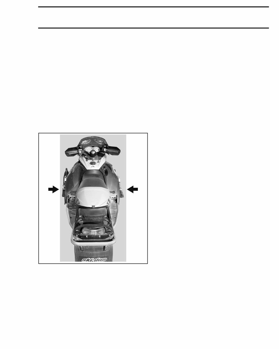
INTRODUCTION MANUAL INFORMATION MANUAL PROCEDURES Many of the procedures in this manual are inter- related. Before undertaking any task, you should read and thoroughly understand the entire section or subsection in which the procedure is contained. A number of procedures throughout the book re- quire the use of special tools. Before starting any procedure, be sure that you have on hand all re- quired tools, or their approved equivalents. The use of RIGHT and LEFT indications in the text are always referenced to the driving position (sit- ting on the vehicle). TYPICAL 1. Left 2. Right This manual uses technical terms which may be different from the ones of the PARTS CATALOGS. When ordering parts always refer to the specific model PARTS CATALOGS. MANUAL LAYOUT This manual is divided into many major sections as can be seen in the main table of contents at the beginning of the manual. Each section is divided into various subsections, and again, each subsection has one or more divi- sions. Illustrations and photos show the typical construc- tion of various assemblies and, in all cases, may not reproduce the full detail or exact shape of the parts used in a particular model vehicle. However, they represent parts which have the same or a similar function.
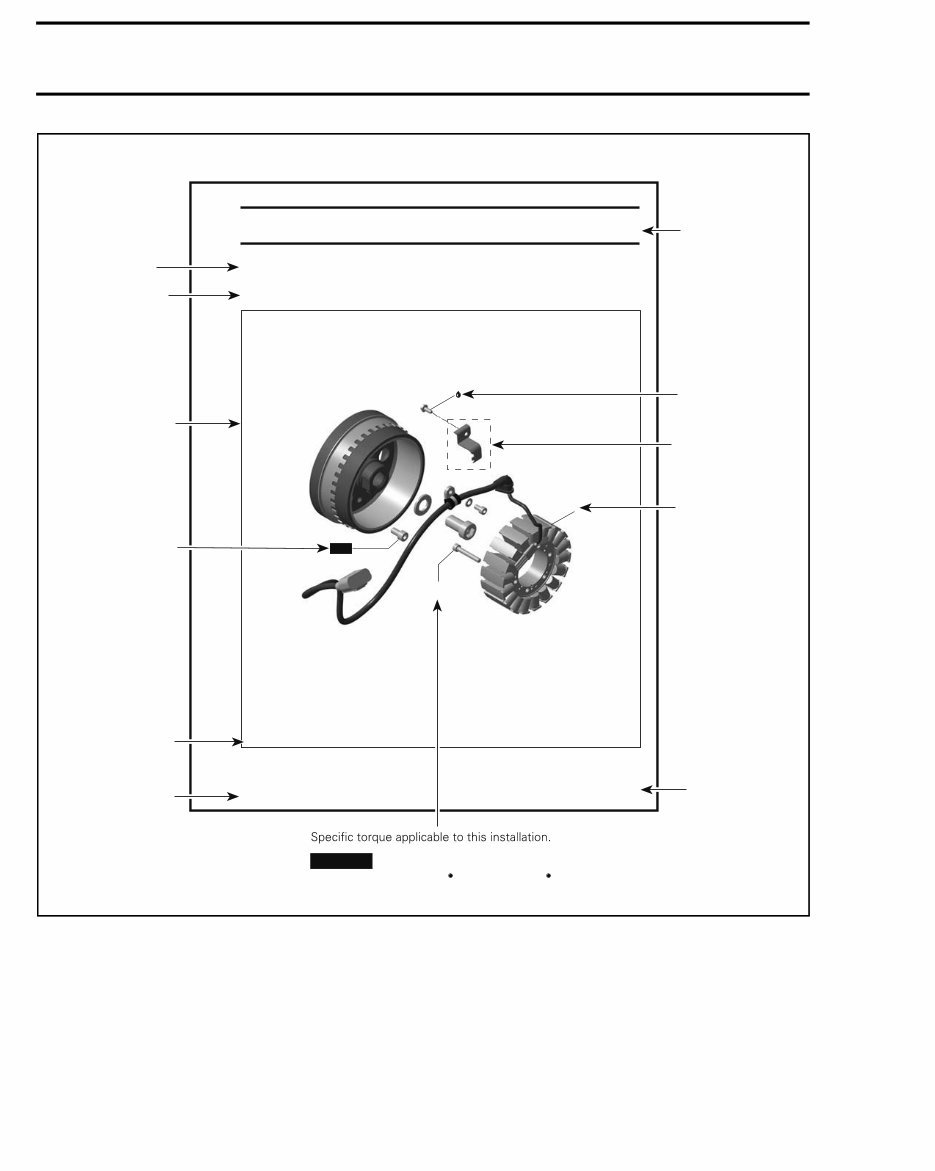
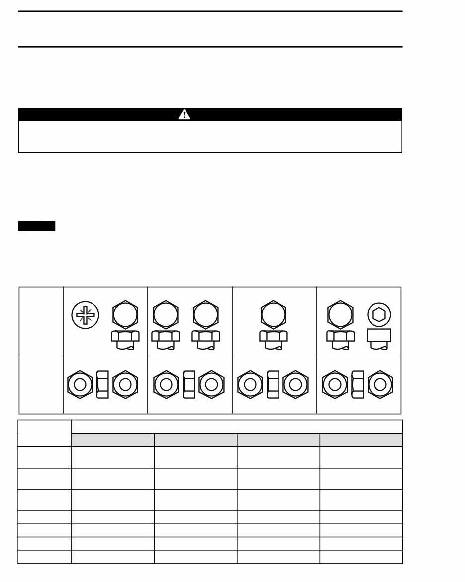
INTRODUCTION TIGHTENING TORQUE Tighten fasteners to the torque specified in the exploded view(s) and/or in the written procedure. When a torque is not specified, refer to the following table. WARNING Torque wrench tightening specifications must be strictly adhered to. Locking devices when removed (e.g.: locking tabs, elastic stop nuts, self-locking fasteners, cotter pins, etc.) must be replaced. In order to avoid a poor assembly, tighten screws, bolts, or nuts in accordance with the following proce- dure: 1. Manually screw all screws, bolts and/or nuts. 2. Apply half the recommended torque value. 3. Tighten fastener to the recommended torque value. NOTICE Be sure to use the recommended tightening torque for the specified fastener used. NOTE: When possible, always apply torque on the nut. NOTE: Always torque screws, bolts and/or nuts using a crisscross pattern when multiple fasteners are used to secure a part (eg. a cylinder head). Some parts must be torqued according to a specific sequence and torque pattern as detailed in the installation procedure. FASTENER GRADE/TORQUE FASTENER SIZE 5.8 Grade 8.8 Grade 10.9 Grade 12.9 Grade M4 1.5 – 2 N•m (13 – 18 lbf•in) 2.5 – 3 N•m (22 – 27 lbf•in) 3.5 – 4 N•m (31 – 35 lbf•ft) 4 – 5 N•m (35 – 44 lbf•ft) M5 3 – 3.5 N•m (27 – 31 lbf•ft) 4.5 – 5.5 N•m (40 – 47 lbf•ft) 7 – 8.5 N•m (62 – 75 lbf•ft) 8 – 10 N•m (71 – 89 lbf•ft) M6 6.5 – 8.5 N•m (58 – 75 lbf•ft) 8 – 12 N•m (71 – 106 lbf•ft) 10.5 – 15 N•m (93 – 133 lbf•in) 16 N•m (142 lbf•in) M8 15 N•m (133 lbf•in) 25 N•m (18 lbf•ft) 32 N•m (24 lbf•ft) 40 N•m (30 lbf•ft) M10 29 N•m (21 lbf•ft) 48 N•m (35 lbf•ft) 61 N•m (45 lbf•ft) 73 N•m (54 lbf•ft) M12 52 N•m (38 lbf•ft) 85 N•m (63 lbf•ft) 105 N•m (77 lbf•ft) 128 N•m (94 lbf•ft) M14 85 N•m (63 lbf•ft) 135 N•m (100 lbf•ft) 170 N•m (125 lbf•ft) 200 N•m (148 lbf•ft)
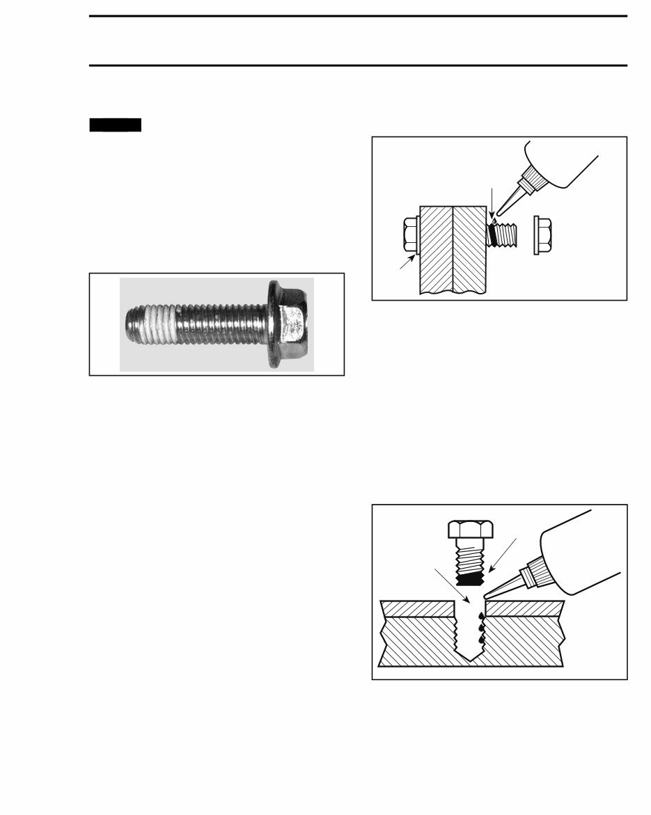
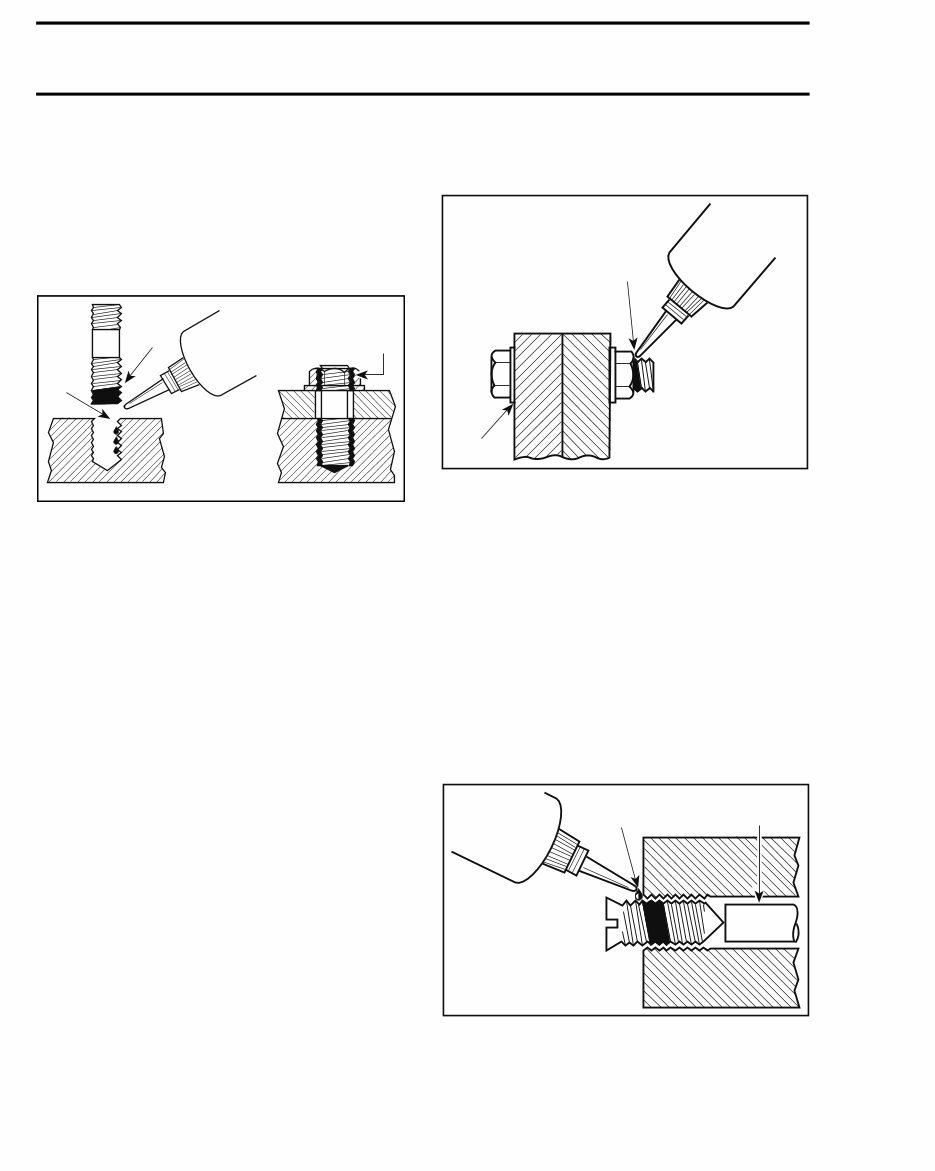
INTRODUCTION FASTENER INFORMATION NOTICE Most components in the vehicles are built with parts dimensioned in the metric system. Most fasteners are metric and must not be replaced by customary fasteners or vice-versa. Mismatched or incorrect fasteners could cause damage to the vehicle or possible personal injury. SELF-LOCKING FASTENERS PROCEDURE A00A6LA TYPICAL — SELF-LOCKING FASTENER The following describes common procedures used when working with self-locking fasteners. Use a metal brush or a tap to properly clean a threaded hole, then use a solvent. Allow the sol- vent time to act, approximately 30 minutes, then wipe off. Solvent utilization is to ensure proper adhesion of the product used for locking the fas- tener. LOCTITE ® APPLICATION PROCEDURE The following describes common procedures used when working with Loctite products. NOTE: Always use proper strength Loctite prod- uct as recommended in this Shop Manual. Threadlocker Application for Uncovered Holes (Bolts and Nuts) 1. Apply here 2. Do not apply 1. Clean threads (bolt and nut) with solvent. 2. Apply LOCTITE PRIMER N (P/N 293 800 041) on threads and allow to dry. 3. Choose proper strength Loctite threadlocker. 4. Fit bolt in the hole. 5. Apply a few drops of threadlocker at proposed tightened nut engagement area. 6. Position nut and tighten as required. Threadlocker Application for Blind Holes lmr2007-040-004_a 1. On fastener threads 2. On threads and at the bottom of hole 1. Clean threads (bolt and hole) with solvent. 2. Apply LOCTITE PRIMER N (P/N 293 800 041) on threads (bolt and nut) and allow to dry for 30 seconds. 3. Choose proper strength Loctite threadlocker.
INTRODUCTION 4. Apply several drops along the threaded hole and at the bottom of the hole. 5. Apply several drops on bolt threads. 6. Tighten as required. Threadlocker Application for Stud Installation in Blind Holes lmr2007-040-005_a 1. On stud threads 2. On threads and in the hole 3. On retaining nut threads 1. Clean threads (stud and hole) with solvent. 2. Apply LOCTITE PRIMER N (P/N 293 800 041) on threads and allow to dry. 3. Put 2 or 3 drops of proper strength Loctite threadlocker on female threads and in hole. NOTE: To avoid a hydro lock situation, do not ap- ply too much Loctite. 4. Apply several drops of proper strength Loctite on stud threads. 5. Install stud. 6. Install cover, part, etc. 7. Apply a few drops of proper strength Loctite on uncovered stud threads. 8. Install and tighten retaining nut(s) as required. Threadlocker Application for Pre-Assembled Parts A00A3OA 1 2 1. Apply here 2. Do not apply 1. Clean bolts and nuts with solvent. 2. Assemble components. 3. Tighten nuts. 4. Apply a few drops of proper strength Loctite on bolt/nut contact surfaces. 5. Avoid touching metal with tip of flask. NOTE: For preventive maintenance on exist- ing equipment, retighten nuts and apply proper strength Loctite on bolt/nut contact surfaces. Threadlocker Application for an Adjustment Screw 1. Apply here 2. Plunger 1. Adjust screw to proper setting. 2. Apply a few drops of proper strength Loctite threadlocker on screw/body contact surfaces. 3. Avoid touching metal with tip of flask.
You're Reading a Preview
What's Included?
Lifetime Access
Fast Download Speeds
Online & Offline Access
Access PDF Contents & Bookmarks
Full Search Facility
Print one or all pages of your manual
$39.99
2012 Ski-Doo MX Z TNT E-TEC 800R Factory Service & Work Shop Manual
Upon purchasing this manual, you will receive a .PDF file containing an email contact. After contacting us, you will receive a reply with a link to access the manual for your 2012 Ski-Doo MX Z TNT E-TEC 800R.
This comprehensive manual covers every aspect of your machine, providing detailed guidance on every nut and bolt. With hundreds of pages, it offers solutions for various issues, from simple tasks like an oil change to more complex procedures like a transmission swap. The manual includes numerous illustrations to assist you and features easy-to-understand text.
Utilize the search function to navigate the manual efficiently and print the necessary pages. This Factory Service Repair Manual is designed to walk you through the fundamentals of maintenance and repair, providing step-by-step instructions to equip you with the knowledge mastered by factory-trained technicians.
By utilizing the insights from this service repair manual, any owner can confidently make informed decisions regarding the maintenance and repair of their machine.
Our commitment extends beyond providing a high-quality service manual; we also ensure excellent customer service, guaranteeing your satisfaction.
Reviews
Q&A
Recently Viewed
5,521,897Happy Clients
2,594,462eManuals
1,120,453Trusted Sellers
15Years in Business
Price:
Actual Price:
2012 Ski-Doo MX Z TNT E-TEC 800R Factory Service & Work Shop Manual