Chapte r One General Inf ormation This Clymer shop manual covers the 1990- 1995 Ski-Doo Formula MX, Formula Plus, For- mula Mach and Grand Touring model s. Troubleshooting, tune-up, maintenance and repair are not difficult. if you know what tools and equipment to use and what to do. Step-by- st ep in struc ti ons guide you through jobs rangi ng from simple maintenance to com pl ete engine and suspension overhau l. This manual can be used by anyone from a first lime do-it-yourselfer to a professional me- chanic. Detailed drawings and clear photographs give you all the information you need to do the work right. Some of the procedures in this manual require the use of special tools. The resourceful me- chanic can, in many cases, think of acceptable substitutes for special tool s-there is always an- other way. This can be as simple as using a few pieces of threaded rod, washers and nuts to re- move or in stall a bearin g or fabricating a tool from scrap material. However, using a s ubstitute for a special 1001 is not recommended as it can be dangerous and may damage the part. If you find thai a 1001 can be designed and safely made, but will require some type of machine work, you may wan t to search out a local community col- lege or high school that has a machine shop curriculum . Shop teachers sometimes welcome outside work thai can be used as practical shop applications for advanced s lUd e nt s. Table 1 li sts model number coverage. General specifications are li sted in Table 2. Table 3 li sts vehicle weight. Metric and U.S. standards are used throughout this manual. U.S. to me tri c conversion is given in Table 4. Critical torque speci fi cations are found in ta- ble form at the e nd of each chapter (as required). The genera ll orque specifications li sted in Table 5 can be used when a torque spec ifi cation is not li sted for a speci fi c component or assembly. A list of general technical abbreviations is given in Table 6. Metric tap drill sizes can be found in Table 7. Table 8 li sts w in dchill factors. t
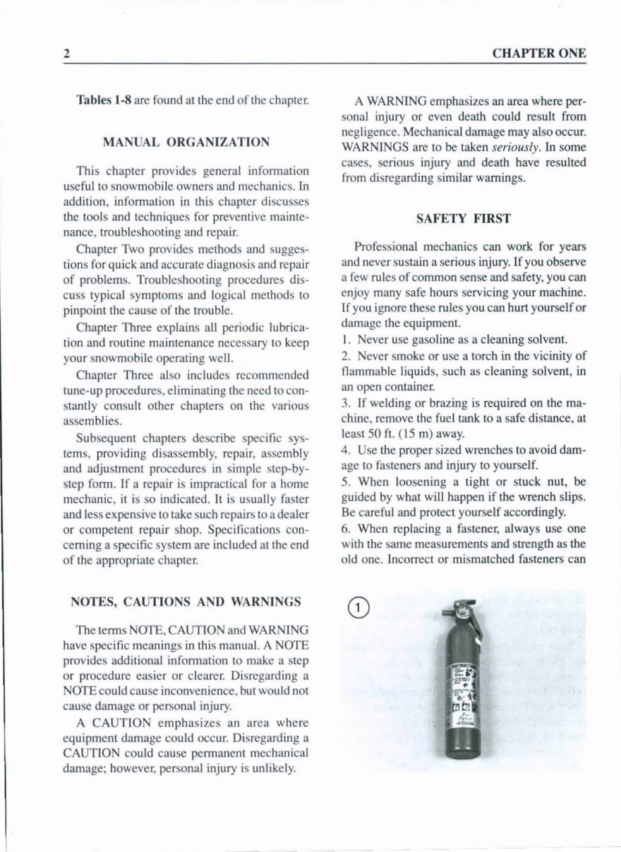
2 Tables 1-8 are found at the end of the chapler. MANUAL ORGANIZATION This chapler provides general infonnution useful to snowmobile owners a nd mechanic s. In addition, infonnalion in this chapler discusses the tools and techniques for preventive mainte- nan ce, troubl es hooting and repair. Chapter Two provides methods and s ugges - tion s for quick and accurate diagnosis and repair of problems. Troubleshooting procedures dis- cuss typical symptoms and logical methods to pinpoint the cause of the trouble. Chapter Three explains all periodic lubrica- lion and routine maintenance necessary to keep your snowmobile operating we ll . Chapter Three also includes recommended tune-up procedures. e lim inating the need to co n- stantly consult other chapters on the various asse mbli es. Subsequent chapters de sc ribe speci fi c sys· tern s, providing di sassembly, repair, assembly and adjustment procedures in simple step· by - step form. If a repair is impractica l for a home mechanic, it is so indicated. It is usuall y faster and le ss expensive to take such repairs to a dealer or co mpet e nt repair shop. Specifications con· ceming a specific syst em are included at the end of the appropriate chapter: NOTES, CAUTIONS AND WARNINGS The tenns NOTE. CAUTION and WARNING have specific meanings in thi s manua l. A NOTE provides additional information to make a step or procedure easier or clearer. Di sregarding a NOTE cou ld cause inconvenience. but wou ld not cause damage or personal injury. A CAUT ION emphasizes an area where equipment damage cou ld occur. Di sregarding a CAUTION co uld cause permane nt mecha ni cal damage; however. personal injury is unlike ly. - - -- - -- - CHAPTER ONE A WARNING emphasizes an area where per· so nal injury or even death could result from negligence. Mechanical damage may also occur. WARNINGS are to be taken serio u sly. in some cases, serious injury and death have resulted from di sregard in g si milar warnings. SAFETY FIRST Profe ss ional mechanics can work for years and never sustain a se riou s injury. If you observe a few rules of com m on sense and safety, you can enjoy many safe hours serv icing your machine. If yo u ignore these rul es you can hurt yourself or damage the equipme nt. I. Never use gasoline as a cleaning solvent. 2. ever smoke or use a torch in the vicinity of flammable liquid s, such as cleaning solvent, in an open co ntain er. 3. If weld in g or brazing is required on the ma - chine, remove th e fue l tank to a sa fe distance, at least 50 ft. ( 15 m) away. 4. Use the proper s ized wrenches to avoid dam- age to fa steners and injury to yo urself. 5. When loosening a ti ght or stu ck nut , be guided by what will happen if the wrench slips. Be careful and protect yourself accordingly. 6. When replacing a fa stener, always use one with th e sa me measureme nt s and strength as the o ld one. In correct or mi smatched fasteners can
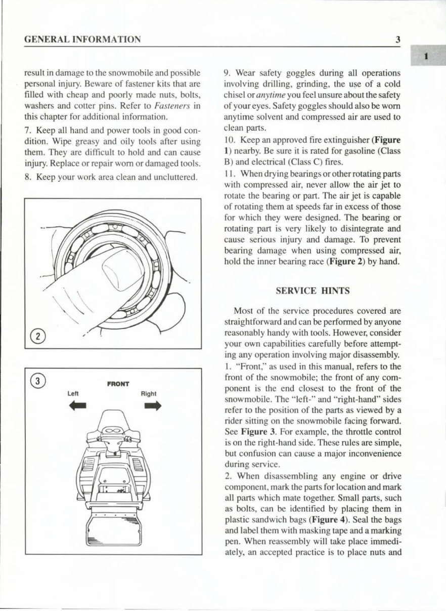
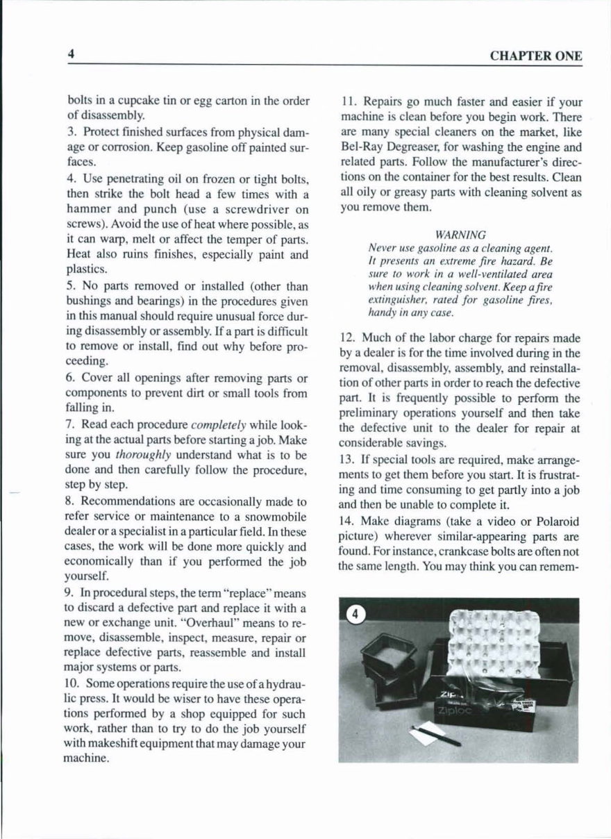
GENERAL INFORMATION resu lt in damage 10 the snowmobile and possible personal injury. Beware of fastener kits thai are fi lled wi th cheap and poorly made nuts, bolts, washers and cotler pins. Refer to Fasteners in this chapter for additional infonna ti on. 7. Keep all hand and power tools in good can· dilion. Wipe greasy and oily tools after using them. They are difficult 10 hold and can cause injury. Replace or repair worn or damaged tools. 8. Keep your wo rk area clean a nd uncluttered. PRONT L on Righi ... 3 9. Wea r safety goggles during all operations involving drilling, grinding, the use of a cold c hi sel orallylime you feel unsure about the safety of your eyes. Safety goggles should also be worn anytime solvent a nd compressed air are used to clean parts. 10. Keep an approved fire ext in guisher (Figure I) n ear by. Be sure it is rated for gasoline (C lass 8) and elec tri cal (Class C) fi res. II . When drying bearings oromer rotating parts with compressed air, never allow the air jet to rotate the bearing or part. The ai r jet is capable of rOlating them at speeds far in excess of those for which th ey were designed. The bearing or rotating pan is very likely to disintegrate and cause serious injury and damage. To prevem bearing damage when us in g compressed air, hold the inner bearing race (Figure 2) by hand. SERVI CE HINTS Most of the servi ce procedures covered are straightforward a nd can be perfonned by an yone reasonably handy wi th tools. However, cons id er your own capabilities carefu ll y before attempt- ing any operation involving major disassembl y. I. "Front:' as used in thi s manual, refers to the front of the snowmobile; the front of an y com- ponent is thc end closest to the front of th e snowmobil e. The "I eft-" and ;'right-hand" sides refer to the position of the parts as viewed by a rider sitting on the snowmobile facing forward. See Figure 3. For example. the throttle control is on the ri ght-hand side. These rules are simple, but confusion can cause a major inconvenience during service. 2. When disassemb lin g any eng ine or drive componem. mark the parts for location and mark all parts which mate together. Small parts, such as bolts. can be identifi ed by placing them in plastic sandwich ba gs (Figure 4). Sea1 the bags and label them with masking tape and a marking pen. When reassembly will lake place immedi- ately. an acceptcd practice is to place nuts and I
4 bolts in a cupcake lin or egg carton in the order of disassembly. 3. Protect finished surfaces from physical dam- age or corrosion. Keep gasoline off painted SUT- faces. 4. Use penetrating oil on frozen or light bolts, then strike the bolt head a few limes with a hammer and punch (use a screwdriver on screws). Avoid the use of heat where possible, as it can warp, meh or affect the temper of parts. Heat also ruins finishes, especially paint and plastics. 5. No pans removed or in stalled (other than bushings and bearings) in the procedures given in this manual should require unusual force dur- ing disassembly or assembly. If a part is difficult to remove or install, find out why before pro- ceeding. 6. Cover all openings after removing parts or components to prevent dirt or small tools from falling in. 7. Read each procedure completely while look- ing at the actual pans before staning a job. Make sure you thoroughly understand what is to be done and then carefu ll y follow the procedure. step by step. 8. Recommendations are occasionally made to refer service or maintenance to a snowmobile dealer or a specialist in a panicular field. In these cases, the work will be done more quickly and eco nomica ll y than if you performed the job yourself. 9. In procedural steps, the term "replace" means to discard a defective pan and replace it with a new or exchange unit. "Overhaul" means to re- move, disassemble, inspect, measure, repair or replace defective pans, reassemble and in stall major systems or pans. 10. Some operations require the use of a hydrau- li c press, It wou ld be wiser to have these opera- tions performed by a shop equipped for such work, rather than to try to do the job yourself with makeshift equipmeOl that may damage your machine. CHAPTER ONE II. Repairs go much faster and easier if your machine is clean before you begin work. There are many special cleaners on the market, like Bel-Ray Degreaser, for washing the engine and related pans. Follow the manufacturer's direc- tions on the container for the best results. Cl ean all oi ly or greasy pans with cleaning so lvent as you remove them. WARNING Never li se gasoline as a cleaning agent. It presellfS an extreme fire hazard. Be sure to work ill a well·vellfilated area whell using cleanillg solvellf. Keep a fire extinguisher, rated for gasoline fires. handy ill any case. 12. Much of the labor charge for repairs made by a dealer is for the time involved during in the removal , disassembly. assembly. and reinstalla- tion of other pans in order to reach the defective pan . It is frequently possible to perform the preliminary operations yourself and then take the defective unit to the dealer for repair at considerable savings. 13. If special tools are required, make arrange- ments to get them before you stan. It is frustrat- ing and time consuming to get panly into a job and then be unable to complete it. 14. Make diagrams (take a video or Polaroid picture) wherever similar-appearing pans are found. For instance. crankcase bolts are often not the same length. You may think you can remem-
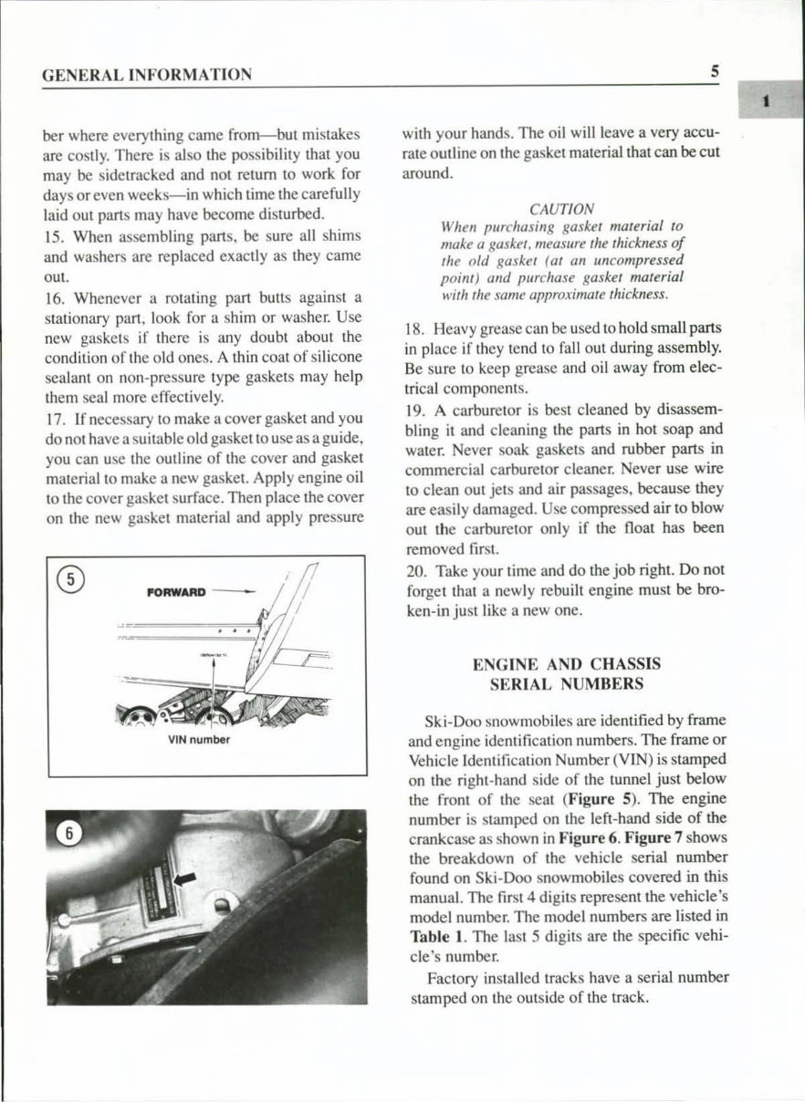
GENE RAL INFORMATION be r where everything ca me from- but mis takes are costl y. There is also th e possibility that you may be s id etracked a nd not re turn to wo rk fo r days or even weeks-in whi ch time the care full y laid o ut pa rt s may have become dis lUr bed. 15. When assembling pans, be sure a ll shims and washers are re pl aced exac tl y as th ey came oul. 16. Whenever a rOlaling pan bUll s against a stationary part. look for a shim or washer. Use new gaskets if th ere is any doubt abo ut th e condition of the old on cs. A th in co at of sili cone sealant on non· press ur e type gaskets may help th em seal more e ffec ti ve l y. 17. If necessary 10 make a cover gasket and you do nol have a suitable old gasket to use as a guide. you can usc th e outline of the cover and gasket material 10 make a new gasket. Apply engine oil to the cover gasket surface. Then pl ace th e cover on the new gasket mate ri al and apply pressure V IN number 5 wi th your hands. The o il will leave a very accu- rate outline on th e gasket material that can be cut around. CAUTION When pllrcha sing gasket material to make a gasket. measure the thickn ess af the old gasket (at an IIn compressed point) and purc hase gaskel material with th e same approximate thickness. 18. Heavy grease can be used to hold small parts in place if they tend to fall out during assembl y. Be sure to keep grease and oil away from elec- trical component s. 1 9. A carburetor is best cleaned by disassem- bling it and cleaning th e parts in hot soap and wate r. Never soak gaskets and rubber parts in commercial carburetor cleaner. Never use wire to clean o ut je ts and air passages, because they are eas il y damaged. Use compressed air to blow o ut the carburetor o nl y if the float has been removed fi rs t. 20 . Take your time and do th e job right. Do not forget that a ne wl y rebuilt engine must be bro- ken-in just like a new one. ENG INE AN D CHASSIS SE RIAL NUMBERS Ski-Doc snowmobiles are identified by frame and e ng in e id entification numbers. The frame or Vehicle Identification Number (YIN) is stamped on the ri g ht -hand s id e of the tunnel just below the fTo nt of th e seal ( Figure 5 ). The engine number is stamped on th e l eft-hand side of the crankcase as shown in Fig ur e 6. Figure 7 shows the breakdown of th e vehicle serial number found on Sk i- Doc snowmobiles covered in this manua l. The first 4 digits represe nt the vehicle 's model number. The model numbers are li sted in Table I. The lasl 5 di g it s are the specific vehi- cl e's number. Factory in sta ll ed tracks have a serial number stamped on th e outside of th e track. I
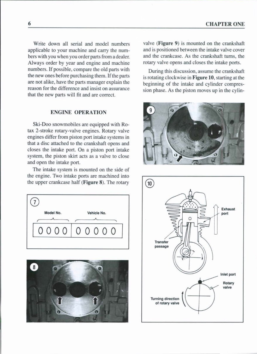
6 Write down all se ri al and model numbers applicable to your machine and carry th e num - be rs with you when you order parts from a dealer. Always o rder by year and eng in e and mac hin e numbers. If possible, compare the old pans with the new ones bef ore pu rc hasing them. lfth e parts are not alike, have the parts manager ex pl a in the reason for the diff erence and insist on assurance that the new parts will fit and are correct ENGINE OPERATION Ski-Doo snowmobiles are equipped with Re - tax 2-s1roke rotary-valve engines. Rotary valve eng in es differ from piston pon intake systems in that a di sc attached to the crank sha ft opens and cl oses th e intake pon. On a pi ston port inrake system. the pi ston skirt acts as a val ve to cl ose and open lhe intake port . The intake system is mounted on th e s id e of th e eng in e. 'TWo intake pons are machined into CHAPTER ONE valve ( Figure 9) is mounted on th e cranksha fl and is pos iti oned between the intake valve cover and th e crankcase. As the crankshaft turns, the rotary valve opens and closes me intake pons. During this discussion, assume me cranksh af t is rotating clockwise in Figure 10, starting at th e beginning of th e intake and cylinder compres- si on phase. As th e piston moves up in th e cylin- th e upper crankcase half (Fig ure 8 ). The rotary ® (j) Model No. Vehicle No. • I , , 10000/00000/ Turning direction 1! 01 rotary val ve \ Exhaust port Inlet port Rotary valve
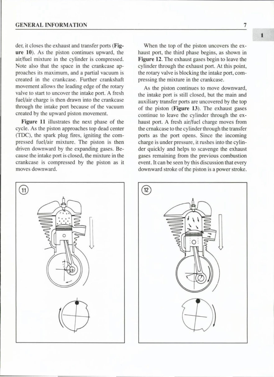
GENERAL INFORMATION d er, it closes the exhaust and transfer ports (Fig- ur e 10). As the pi ston continues upward, th e air/fuel mi xture in th e cylind er is compressed. NOIe also that the space in the crankcase ap- proaches il s maxi mum, and a partial vacuum is created in the crankcase. Further crankshaft movement a ll ows th e leading edge of th e rotary va lve 10 sla rt to un cover th e intake port. A fresh fuel/air charge is then drawn into the crankcase through th e intake pon because of the vacuum created by th e upward piston movement. Figure I J illustrates th e next phase of the cycle. As the piston approaches lOp dead center (TDe), the spark plug fires. igniting the com- pressed fu el/ai r mi xture. The piston is th en driven downward by th e ex panding gases. Be- ca use th e intake pon is closed, the mixture in the crankcase is co mpressed by th e pi ston as it moves downward. @ 7 When th e top of the piston uncovers the ex- haust pon, the third phase beg in s. as shown in Fig ur e 12. The exhau st gases begin to leave th e cylinder through th e exhaust port. At this point. th e rotary valve is bloc king th e in take pon , com- pressing th e mixture in the crankcase. As the pi ston continues to move downward. the intake pon is still closed, but the main and auxiliary transfer pons are uncovered by the lOp of th e pi slon (Fig ure 13). The exhaust gases continue to leave the cylind er through the ex- haust port. A fresh air/fuel charge moves from the cmakcase to th e cylinder through th e tran sfer ports as th e pon opens. S ince the incoming charge is under pressure, it ru shes into the cy lin- der quic kl y and he lp s 10 scavenge the exhaust gases remaining from the previous combustion event. It can be seen by this di scussion that every downward stroke of th e pi ston is a power stroke. ® I
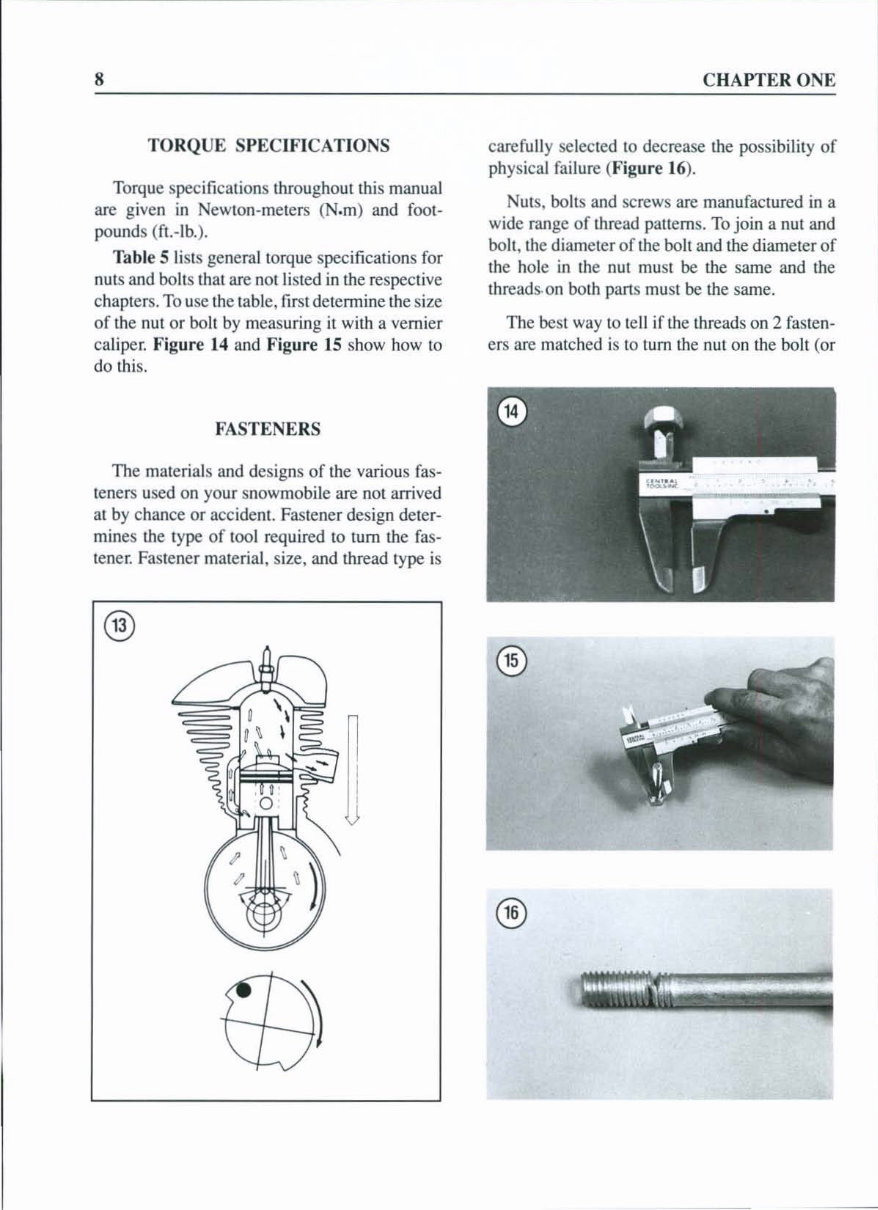
8 TORQUE SPECIFICATIONS Torque specifications lhroughoul this manual are g iven in Newton-meters (N.m) and fool- pounds (fl.-lb.). Table 5 li sts general torque spec ifications for nuts and bolts that are nOllisted in the respective chaplers. To use th e table, fir st detennine the si ze of the nul or bo lt by measuring it with a vernier caliper. Figure 14 and Figure 15 show how to do thi s. FASTENERS The materials and designs of the various fa s- teners used on your snowmobile are not arri ved al by chance or accident. Fastener design deter- mines th e type of tool required to tum the fa s- tener. Fastener material, size, and thread t ype is ® CHAPTER ONE carefully selected to decrease the possibility of physical failure (Figure 16). Nut s. bolts and screws are manufactured in a wide range of thread patte rn s. To join a nut and boh, th e diameter of the boh and the diameter of the hole in th e nut must be the same and th e threads·on both parts must be the same. The best way to te ll if th e th reads on 2 fa sten- ers are matched is to tum the nut on the bolt (or ®
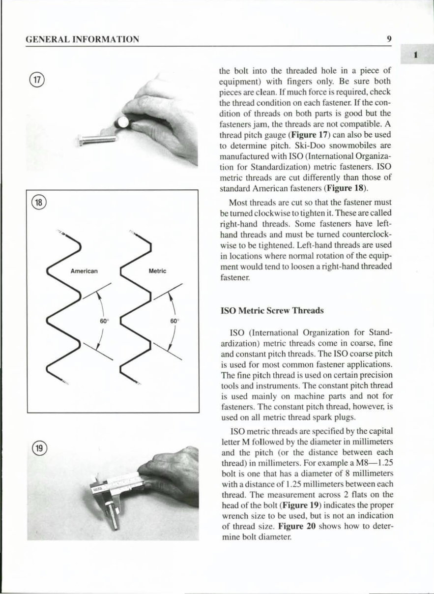
GENERAL INFORMATION ® ® 9 the boh into th e threaded hole in a piece of equ ipment) with fin gers o nl y. Be sure both pieces are clean. If much force is required, check the thread co ndition on each fastener. If the con- dition of threads on both parts is good but the fa steners jam. the threads are not compatibl e. A thread pitch gau ge (Figure t 7) can also be used to detenninc pitch. Ski-Doo snowmobiles are manufactured with ISO (International Organiza- lion for Standardizati on) melric fasteners. ISO metri c thr eads are c ut differently than those of standard Ame ri can fa steners (F igure 18 ). Most thr eads are cut so that the fa stener must be turned clockw ise to tighten it . These are called ri ghi -ha nd threads. Some fasteners have left- hand threads and mu st be turned co unterclock- wise to be ti ghtened. Left-hand threads are used in loca ti ons where nonnal rota ti on of the equip- me nt wou ld te nd to loosen a rig ht -hand threaded fa stener. ISO Metric Screw Threads ISO (I nternati onal Orga ni zation for Stand- ardizati on) metric thre ad s come in coarse, fine and constant pitch threads. The ISO coarse pitch is used for most co mmon fa stener applications. The fin e pitch thread is used on certain precision tools and instrume nt s. The constant pitch thread is used mainly on machine parts and not for fasteners. The co nstant pitch thread, however, is used on all me tri c thread spark plugs. ISO metric threads are specified by the capital lett er M fo ll owed by the diameter in millimeters and th e pitch (or the di stance between each thread) in millimeters. For example a M8- 1.25 bolt is one th at has a diameter of 8 millimeters with a distance of 1 .2 5 millimeters between each thread. The measurement across 2 flats on the head of the bo ll ( Figure t 9) indicates lh e proper wrench size to be used. but is not an indicati on of thread size. Figure 20 shows how to deter- mine bolt diameter. I
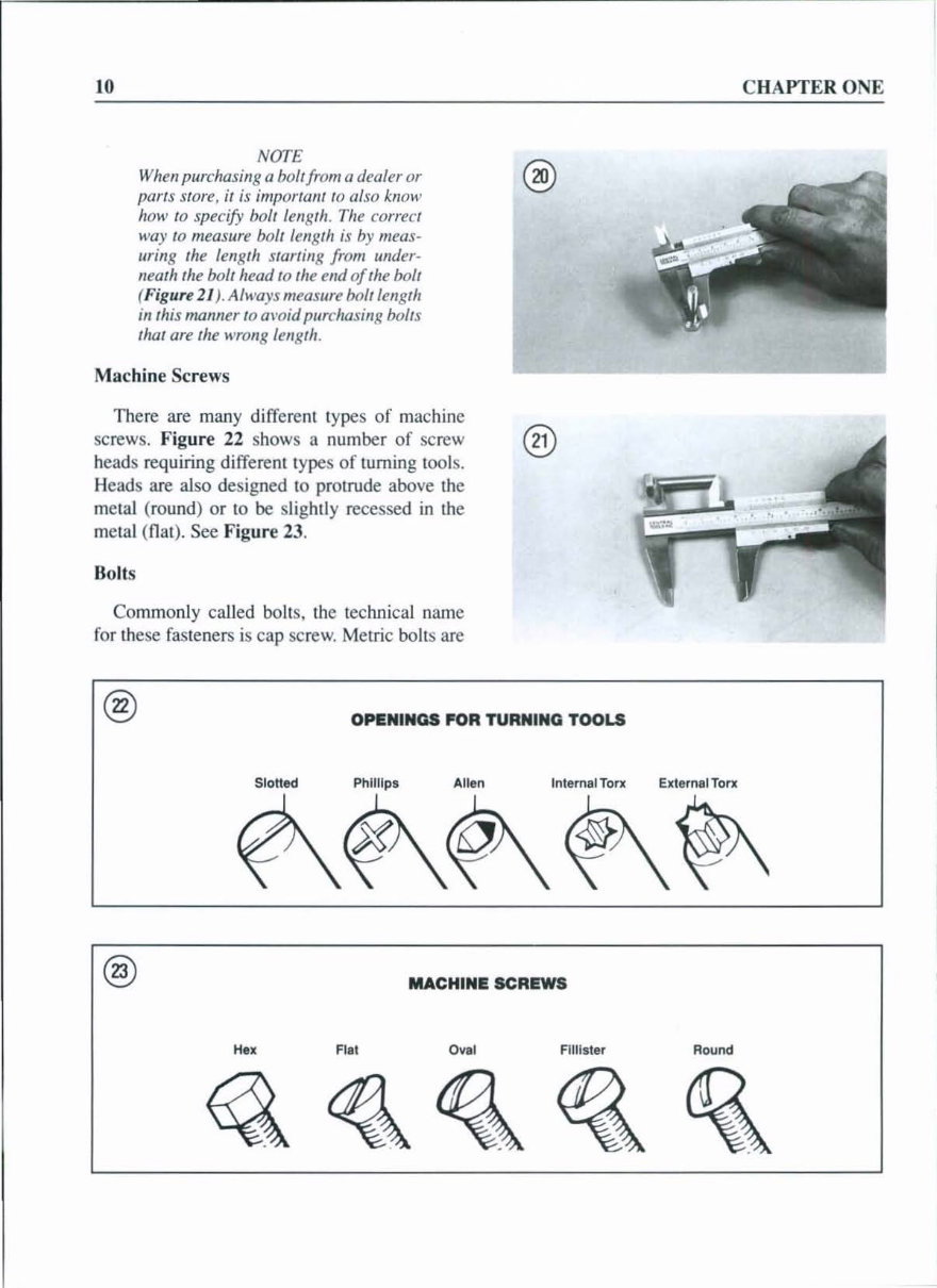
10 NOTE When purchasing a boll from a dealer or parts store, ;1 is important 10 a/so kllOw how to specify bolt lellgl h. The con'eel way to measure bolt length is by meas- uring the length starting from under. neath the bolt head to lhe end of the bolt ( Fig ure 21). Always measure bolt lell8,h in this mallner roa\'Oid pure/lOsing boIlS ,hal are fhe wrong lellgth. Mac hine Screws There are many different types of machine screws. Fi gur e 22 shows a num be r of screw ® heads requiring different types of turning too ls. Heads are also designed 10 protrude above th e metal (round) or to be s li ghtly recessed in th e melal (nat). See Fig ur e 23. Bolts Commonly ca ll ed bo lt s. th e technical name for these fasteners is cap screw. Metric bo lts are @ OPENINGS fOR TURNING TOOLS Slotted Phillips Allen IntematTorx ?\~~ @ MACHINE SCREWS H e, Flat Oval FII1i ster CHAPTER ONE External Ton: Round
You're Reading a Preview
What's Included?
Lifetime Access
Fast Download Speeds
Online & Offline Access
Access PDF Contents & Bookmarks
Full Search Facility
Print one or all pages of your manual
$27.99
1990-1995 Ski Doo Formula Snowmobile Service & Repair Manual
This service repair manual covers Ski-Doo snowmobiles manufactured between 1990 and 1995. It provides detailed information, diagrams, and photos for the Formula Series Snowmobiles and may be applicable to other models within this time frame. The manual consists of 528 pages and includes the following chapters:
Chapter One: General Information
Chapter Two: Troubleshooting
Chapter Three: Lubrication, Maintenance, and Tune-up
Chapter Four: Adjustments for Special Use
Chapter Five: Engine
Chapter Six: Fuel System (Carbureted Models)
Chapter Seven: Fuel System (Fuel Injected Models)
Chapter Eight: Exhaust Systems
Chapter Nine: Electrical System
Chapter Ten: Oil Injection System
Chapter Eleven: Liquid Cooling System
Chapter Twelve: Recoil Starter
Chapter Thirteen: Drive System
Chapter Fourteen: Brake, Jackshaft, Chaincase, and Drive Axle
Chapter Fifteen: Front Suspension and Steering
Chapter Sixteen: Track and Rear Suspension
Chapter Seventeen: Off-Season Storage
The manual also includes an index and wiring diagrams. It covers models such as Formula Mach 1 XTC, Formula MX, Formula MX E, Formula MX XTC R, Formula MX Z, Formula Plus, Formula Plus E, Formula Plus EFI, Formula Plus LT, Formula Plus X, Formula Plus XTC, Formula Plus XTC E, Formula SS, Formula ST, and Formula STX, as well as other models produced between 1990 and 1995.
This manual provides instant access without any shipping costs or the need to wait for a CD-ROM.
Reviews
Q&A
Recently Viewed
5,521,897Happy Clients
2,594,462eManuals
1,120,453Trusted Sellers
15Years in Business
Price:
Actual Price:
1990-1995 Ski Doo Formula Snowmobile Service & Repair Manual



 Lifetime Access




