Foreword This manual is designed primarily for use by snow- mobile mechanics in a properly equipped shop. However, it conta ins enough deta il and basic in- formation to make it useful to the snowmobile user who desires to perform his own ba sic mainte- nance and repair work. A basic knowledge of mechanics, the proper use of tools, and workshop procedures must be understood in order to carry out maintenance and repair sa tisfactorily . When- ever the owner has insufficient exper ience or doubts his ability to do the work, the adjustments, maintenance, and repair should be carried out only by qualified mechanics. In order to perform the work efficien t ly and to avoid costly mistakes, the mech anic shou ld read the text. thoroughly familiarize him se lf with the procedu res before starting work, and then do the work carefully in a clean area. Whenever special tools or equipment is specified, makeshift too ls or equipment should not be used. Precision measure - ments can only be made if the proper in struments are used, and the use of substitute tools may adversely affect safe operation of the s nowmobi le. Wh enever you see the symbols shown below, heed their instructions! Always follow safe operat ing and maintenance practices. IWA RNING' Th is warning symbol identifies special in - structions or procedures which. if not cor- rectly followed, could result in pe rsonal Injury, or loss of life. This caution symbol identifies special in - structions or procedures which. if not strictly observed, co uld result in damage to, or destruction of equipment. NOTE: Indicates po i nts of particular interest for more efficient and convenient operat ion. This manual is divided int o the following fo ur sections: (1) Spec ifi cations This section contains general and techn ical spec ifi - cations, a complete torque chart and engine per- formance cu rves. (2) Maintenance and Theory of Operation The procedures for in spection, adjustments and minor repair are described in this sect ion. An expl anat ion on the structu re and f unction of each of the major components and assembly enables the mechanic to better understand what he is doing. (3) Repair This sec tion shows the best method for removal, disassembly , inspection, asse mbly , and in st allatio n whi ch are necessary for proper maintenance and repair. Assembly and installation notes are pro- vided to expla in special points. (4) Appendix The appendix in the back of the manual contains miscellaneous in formati on, including metric refer- ence and conversion charts , special tools, wiring diagram, and an index . This shop man ual has been prepared to assist the mechanic in serv i cing the KAWASAKI snow- mobiles. All pr ocedures contained within should be followed closely . FOR EWORD
Quick Reference Guide S "f" " peci Icatlons .. ......................... .................................................................... . Maintenance and Theory ............................................................... .. .......... . Repair .......... . .. .. ........... ............................ .. . ... .. .............................................. . Appendix ....... .. .................................. .................. .. .............. ........... . .. ............ . Using the quick reference guide will assist you in quickly locating a desired topic or procedure contained within this shop manual. Bend the pages back until you match the de- sired section above with the black tab on the right hand side of the table of contents for that section. Refer to the table of contents for the exact page(s) to locate the specific topic or procedure required. SECTION QUICK REFERENCE GUIDE ii
Specifications Table of Contents Page General Specifications . . . . . . . . . . . . . . . . . . . . . . 1-2 Service Specifications .. ....... .. ... .. . .... . 1-5 Torque Chart and Loctite Table .. ... .. . .. ... 1-6 Gear Ratio Chart ....... . .... ..... ... .... 1-10 Port Dimensions/Eng ine Performance Curves . . . . . . 1-11 SPECIFI C ATIONS 1-1
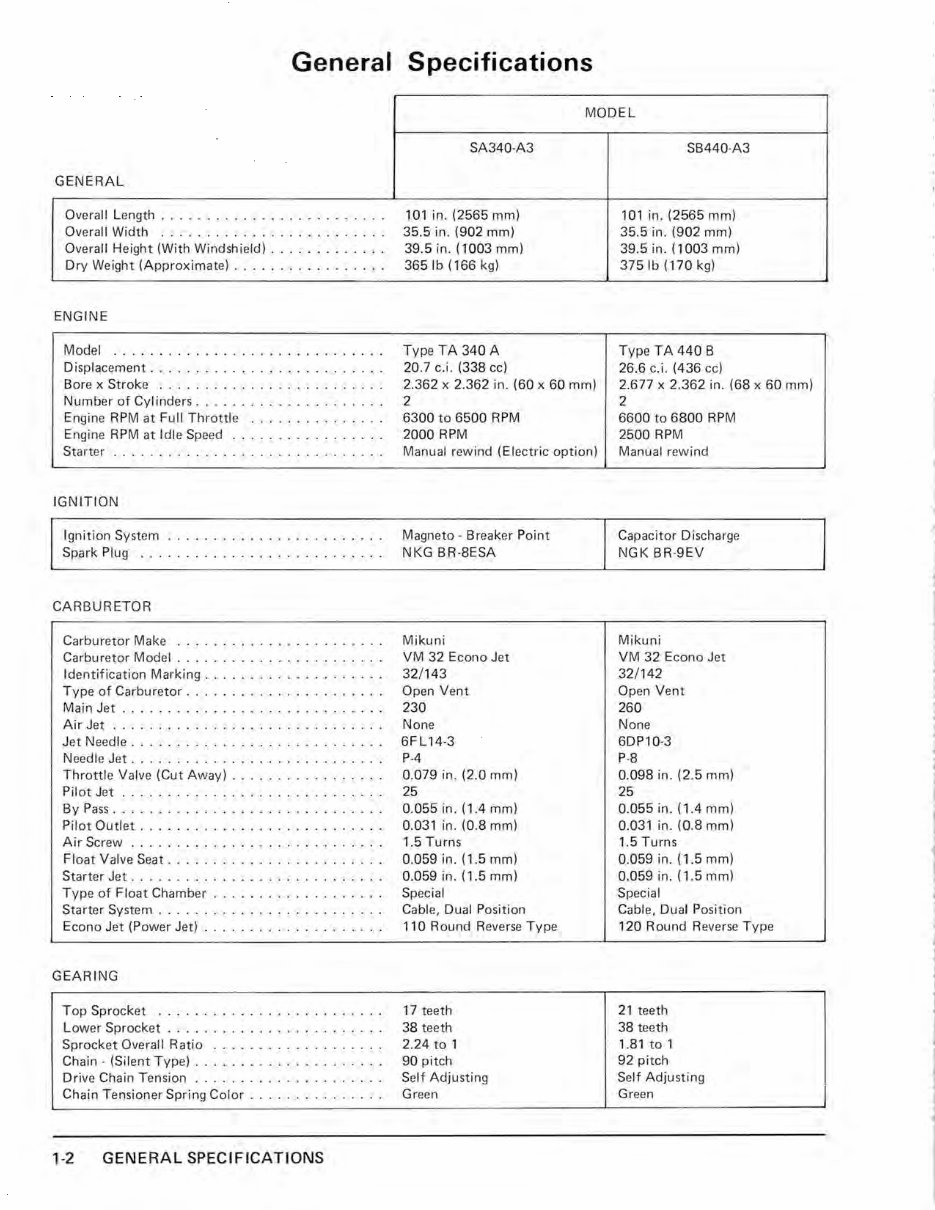
General Specifications GENERAL Overall Length ... ... .. .. . .. ... _ ........ Overal l Width .................. . ...... Ov erall Height (With Windshield) . . ...... . ... . Dry Weight (Approximate) ... ... ..... ...... ENGINE Mode l ......... .. ...... .... .. ..... . . Displacement ..... ... .. ... .. .... . ..... . Bore x Strok e . . ..... .. .. . ............ . Number of Cylind ers .. . .. ... .... .... ... . . Engine RPM at Fu ll Throttle . .... ......... . Engine RPM at Idle Sp eed ....... . .... . ... . Starter ........ .. ..... . ....... .. . ... . IGNITION Ignition System ..... . ...... .... .... .. . . Spark Pl ug .... . .......... .. .. .. .... . . CARBURETOR Carburetor Make Carburetor Model ................... . .. . Identification Marking .... . .... ... ..... . . . Type of Car buretor ... . ....... . ......... . Main Jet ... . .. .... . .... ... . .. ....... . Air Jet ...... .. ........ .. ... ..... . . . . Jet Needle ... . ... ..... .. . ..... ... ... . . Needle Jet .... .. ...... ....... .. .. . ... . Throttle Valve (Cut Away) ......... .. .. . .. . Pilot Jet ... ........ ...... .... .. .. . . . . By Pass .. ... ... ................... . . . Pilot Outlet ....... . ... . ... .... . ...... . Air Sc rew . ....... ... .. ....... .. .. . .. . Float Valve Seat . .. .. . .. . .. . ..... .. .... . Starter Jet . .. .. .. ........... . ........ . Type of Float Ch amber ......... .. . ... . . . . Starter Sy stem ... ..................... . Econo Jet (Power Jet) ........... .. ..... . . GEARING Top Sprocket .. . ................... . . . Lower Sprocket . ... . .. ... ........... . . . Sprocket Overall Ratio . .. ......... . .... . . Chain - (Silent Typ e) ..... .. ... . ... . .. ... . Dr ive Chain Tension ... .. .. .. ........... . Chain Tensioner Spring Color . .. .......... . . 1-2 GENERAL SPECIFICATIONS MODEL SA340-A3 101 in. (2565 mm) 35.5 in. (902 mm) 39.5 in. (1003 mm) 3651b (166 kg) Typ e TA 340 A 20 .7 c.i. (338 cc) 2.362 x 2.362 in. (60 x 60 mm) 2 6300 to 6500 RPM 2000 RPM Manual rewind (Electric option) Magneto - Breaker Point NKG BR-8ESA M ikuni VM 32 Econo Jet 32/143 Op en Vent 230 None 6F L 14-3 P-4 0.079 in. (2.0 mm) 25 0.055 in. (1.4 mm) 0.031 in. (0.8 mm) 1.5 Turns 0.059 in. (1.5 mm) 0.059 in. (1.5 mm) Sp ecial Cabl e, Dual Position 110 Round Reverse Type 17 teeth 38 teeth 2.24 to 1 90 pitch Self Adjusting Green SB440-A3 101 in. (2565 mm) 35.5 in. (902 mm) 39.5 in. (1003 mm) 3751b (170 kg) Typ e TA 440 B 26.6 c.i. (436 cc) 2.6 77 x 2.362 in. (68 x 60 mm) 2 6600 to 6800 RPM 2500 RPM Manual rewind Capacitor Discharge NGK BR-9EV Mikuni VM 32 Econo Jet 32/142 Op en V ent 260 None 6DP10-3 P-8 0.098 in. (2.5 mm) 25 0.055 in. (1.4 mm) 0.031 in. (0.8 mm) 1.5 Turns 0.059 in. (1.5 mm) 0.059 in. (1 .5 mm) Special Cable, Dual Position 120 Round Reverse Type 21 teeth 38 te eth 1.81 to 1 92 pitch Self Adjust i ng Green J J j 1 1 1 J
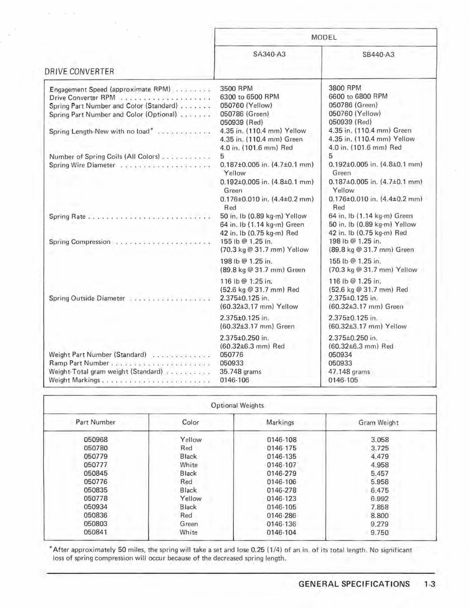
DRIVE CONVERTER Engagement Speed (approximate RPM) ... . ... . Dr ive Converter RPM .......... ...... . .. . Spring Part Numb er and Color (Standard) ... .. . . Spring Part Number and Color (Optional) .. .. .. . Spring Length-New with no load * . .. .. ... ... . Number of Spring Coils (All Colors) . ... .. ... . . Spring Wir e Diamet er ..... .. ... .. . ..... . . Spring Rate ....... .. ........... ... ... . Spring Compression .. . ....... _ . . ..... .. . Spring Outside Diameter .... . ............ . Weight Part Number (Standard) ............ . Ramp Part Number ..... . .... . ... .... ... . Weight-Total gram weight (Standard) ... .... . . . Weight Markings ........ .. ........ .. . .. . Part Number Color 050968 Yellow 050780 Red 050779 Black 050777 White 050845 Black 050776 Red 050835 Black 050778 Yellow 050934 Black 050836 Red 050803 Green 050841 White MODEL SA340-A3 3500 RPM 6300 to 6500 RPM 050760 (Yellow) 050786 (G reen) 050939 (R ed) 4.35 in. (110.4 mm) Y ellow 4.35 in. (110.4 mm) Green 4.0 in. (101.6 mm) Red 5 0.187±0.005 in. (4.7±0.1 mm) Yellow 0. 192±0.005 in. (4.8±0.1 mm) Green 0. 176±0.01O in. (4.4±0.2 mm) Red 50 in. Ib (0.89 kg-m) Yellow 64 in.lb (1 .14 kg-m) Green 42 in. Ib (0 .75 kg-m) Red 1551b @ 1.25 in. (70.3 kg@ 31 .7 mm) Yellow 1981b @ 1.25 in. (89.8 kg @31.7 mm) Green 116 Ib @ 1.25 in. (52.6 kg @ 31 .7 mm) Red 2.3 75±0.125 in. (60.32±3.17 mm) Yellow 2.375±0.125 in. (60.32±3.17 mm) Green 2.375±0.250 in. (60.32±6.3 mm) Red 050776 050933 35.748 grams 0146-106 Optional Weights Markings 0146-108 0146-175 0146-135 0146-107 0146-279 0146-106 0146-278 0146-123 0146-105 0146-286 0146-136 0146-104 SB440-A3 3800 RPM 6600 to 6800 RPM 050786 (Green) 050760 (Yellow) 050939 (Red) 4.35 in. (110.4 mm) Green 4.35 in. (110.4 mm) Yellow 4.0 in. (1 01.6 mm) Red 5 0.192±0.005 in. (4. 8±0.1 mm) Green 0.187±0.005 in. (4.7±0.1 mm) Yellow 0. 176±0.010 in. (4.4±0.2 mm) Red 64 in.lb (1 .14 kg-m) Green 50 in. Ib (0.89 kg-m) Yellow 42 in. Ib (0.75 kg-m) Red 198 Ib @ 1.25 in. (89.8 kg @3 1.7 mm) Green 1551b @ 1.25 in. (70.3 kg @3 1.7 mm) Yellow 116Ib@1.25in. (52.6 kg @ 31 .7 mm) Red 2.375±0. 125 in. (60.32±3.17 mm) Green 2.375±0.125 in. (60.32±3.17 mm) Yellow 2.3 75±0.250 in. (60.32±6.3 mm) Red 050934 050933 47.148 grams 0146-105 Gram Weight 3.058 3.725 4.479 4.958 5.457 5.958 6.475 6.992 7.858 8.800 9.279 9.750 * After approximately 50 miles, the spring will take a set and lose 0.25 (1/4) of an in. of its total length. No significant loss of spring compression will occur because of the decreased spring length. GENERAL SPECIFICATIONS 1-3
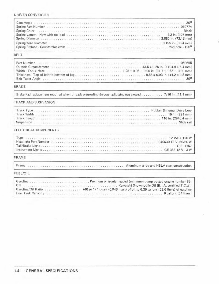
DRIVEN CONV ERTER Cam Angle . ... .. ... . .... . ........ .. .. .. ........ .. .. . ... . .. .. .. .. .... .. . .. ... .... 30 0 Spring Part Number .. . .... ..... .. . .. . ... . .... . ....... .. ... . ....... ... .. ..... .. . .. 050774 Spring Color . . . . . . . . . . . . . . . . . . . . . . . . . . . . . . . . . . . . . . . . . . . . . . . . . . . . . . . . . . . . . . . . . . .. Black Spring Length - New with no load . .. .. _ . . . . . . . . . . . . . . . . . . . . . . . . . . . . . . . . . . . . . . 4.2 in. (107 mm) Spring Diameter . ......... . .. . ..... .. .. ........ . .. .. ...... ... .. . ... . .... 2.880 in. (73 .1 5 mm) Spring Wire Diameter .... .. .... .. .. .. ... . .... ... .... .. .. ............. .. .. 0.155 in. (3.94 mm) Spring Preload - Counterclockwise. . . . . . . . . . . . . . . . . . . . . . . . . . . . . . . . . . . . . . . . . . . . . .. 2nd hole - 120 0 BELT Part Number ... ........... . ............. . ..... .. . ... . ..... . ... . ... . ...... . ..... 050655 Outside Circumference ........ .... . ... .. .. .. .. ... ............... 43.5 ± 0.25 in. (1 104.9 ± 6.4 mm) Width - Top surface .. ..... .. .. .. .. ... .... . .. . .. .. .. .. . 1. 25 + 0.06 - 0. 00 in. (3 1. 7 + 1.55 - 0. 00 mm) Thickness - T op of belt to bottom of lug . .. . .. ... . .. ... ..... . ......... . . . 0.56 ± 0.03 in. (14.2 ± 0.8 mm) Belt Taper Angle .... . .. . .... . ... .... _ ............. .. ... . ..... _ . . . . . . . . . . . . . . . . . . .. 30 0 BRAKE Brake Pad replacement required when threads protruding through adjusting nut exceed ... .. . .... 7/ 16 in. ( 11 .1 mm) TRACK AND SUSPENSION Track Type . ..... .. .. ...... ... ..... .... ... . .. ... ...... ..... .. .. .. Rubber (Internal Drive Lug) Track Width . .. .... . ... . .......... . .. . ........... ... ... . . . _ . . _ ...... . .... 15 in. (381 mm) Track Length ... .. . ..... .. .. .. .. . .. . .. .... .. . .. .......... .. .. . ......... 116 in. (2946.4 mm) Suspension .... ...... ...... .. .. . ..... ... .... . ....... . .... . ... .. . ........... .. . Slide rail ELECTRICAL COM P ONENTS Type .. . .. . ... . .. .. . .... .... .. .. ... .. .. . ... ..... ... ... .. . ...... .. .. .. .. 12 VAC , 120 W Headlight Part Number ...... . ... .. ...... . .. ... ... . ..... .. .... . ...... .... 04 063012 V. 60/ 60 W Tail/Brake Light ....... _ . . .. .. .. . ......... . .. .. ... .... ... ....... ... ... ..... . .. . G.E.1 157 Instrument Lights . . .. . .... ..... ...... . .... .. ........... .. .. . .. . ... ... .. .. GE 36312 V - 3 W FRAME Frame Al uminum all oy and HSLA st eel construction FUE L/OIL Gasoline ....... .... . ..... ...... ..... Prem ium or r egu lar l ea ded (minimum pump posted oct ane number 89) Oil .. .......... .. .. ... .... . ..... . ....... .. .... . Kawasak i Sn owmobi le Oil (B . I.A. certified T.C.W.) Gasoline/Oil Ratio ...... ... ... .. . .. (40 to 1) 1 qu ar t (0.946 liters) of oil to 6.25 ga llons (23.6 liters ) of gasol i ne Fuel Tank Capacity ... .. .. .. .. .. .. .. . ......................... ... ... .. . .. 9 gallons (34 lit ers ) 1-4 GENERAL SPECIF ICATI ONS
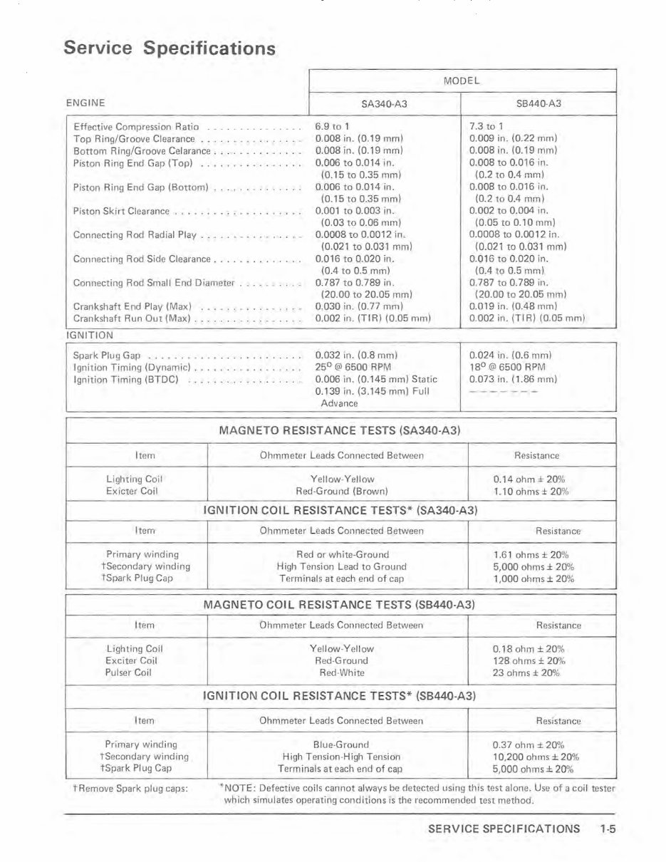
Service Specifications MODEL ENGINE SA340-A3 SB 440-A3 Effective Compression Ratio ... . ... . .. . .. .. 6.9 to 1 7.3 to 1 Top Ring/Groove Clearance · . .... . ......... 0. 008 in. (0.19 mm) 0.009 in. (0.22 mm) Bottom Ring/Groove Celarance .... ... ...... . 0.008 in. (0.19 mm) 0.008 in. (0.19 mm) Piston Ring End Gap (Top) · . ..... ... .. .... 0.006 to 0.014 in. 0.008 to 0.016 in. (0.15 to 0.35 mm) (0.2 to 0.4 mm) Piston Ring End Gap (Bottom) .. .. .. . ... . ... 0.006 to 0.014 in. 0. 008 to 0.016 in. (0.15 to 0.35 mm) (0.2 to 0.4 mm) Piston Skirt Cl earance .. . .. . ... _ .. . ..... .. 0.001 to 0.003 in. 0.002 to 0.004 in. (0.03 to 0.06 mm) (0.05 to 0.10 mm) Connecting Rod Radial Play .. .. .. . .. _ . .. . .. 0.0008 to 0.0012 in. 0.0008 to 0.0012 in. (0.021 to 0.031 mm) (0.021 to 0.031 mm) Connecting Rod Side Clearance ... ... .. ...... 0.016 to 0.020 in. 0.016 to 0.020 in. (0.4 to 0.5 mm) (0.4 to 0.5 mm) Connecting Rod Small End Diameter .......... 0.787 to 0.7 89 in. 0.787 to 0.789 in. (20.00 to 20.05 mm) (20.00 to 20.05 mm) Crankshaft End Play (Max) · .... . .. .. ... . .. 0.030 in. (0.77 mm) 0.019 in. (0.48 mm) Crankshaft Run Out (Max) ......... .. ...... 0.002 in. (TIR ) (0.05 mm) 0.002 in. (TI R) (0.05 mm) IGNITION Spark Plug Gap . .......... .. ... .. .. .... 0.032 in. (0.8 mm) 0.024 in. (0.6 mm) Ignition Timing (Dynamic) ................ . 25 0 @ 6500 RPM 18 0 @ 6500 RPM Ignition Timing (BTDC) ... .. ...... .. ... .. 0.006 in. (0.145 mm) Static 0.073 in. (1 .86 mm) 0.139 in. (3.145 mm) Full --- - --- Advance MAGNETO RESISTANCE TESTS (SA340-A3) Item Lighting Coil Exicter Coil Item Primary winding tSecondary winding tSpark PI ug Cap Item Lighting Coil Exciter Coil Pulser Coil Item Primary winding tSecondary winding tSpark PI ug Cap tRemove Spark plug caps: Ohmmeter Leads Connected Between Resistance Yellow -Yellow 0.14 ohm ± 20% Red -Ground (Brown) 1. 100hms± 20% IGNITION COIL RESISTANCE TESTS* (SA340-A3) Ohmmeter L eads Connected Between Resistance Red or white-Ground 1. 610hms± 20% High Tension L ead to Ground 5,000 ohms ± 20% T erminals at each end of cap 1,0000hms± 20% MAGNETO COIL RESISTANCE TESTS (SB440-A3) Ohmmeter L eads Connected Between Resistance Y ellow-Yellow 0.18 ohm ± 20% Red-Ground 128 ohms ± 20% Red-Wh ite 23 ohms ± 20% I GNITION COIL RESISTANCE TESTS* (SB440-A3) Ohmmeter Leads Connected Between Resistance Blue-Ground 0.37 ohm ± 20% High Tension-High T ens i on 10,200 ohms ± 20% Terminals at each end of cap 5,000 ohms ± 20% *N OTE: Defective coils cannot always be detected using this test alone. Use of a coil tester which simulates operating conditions is the recommended test method. SERVICE SPECIFICATIONS 1-5
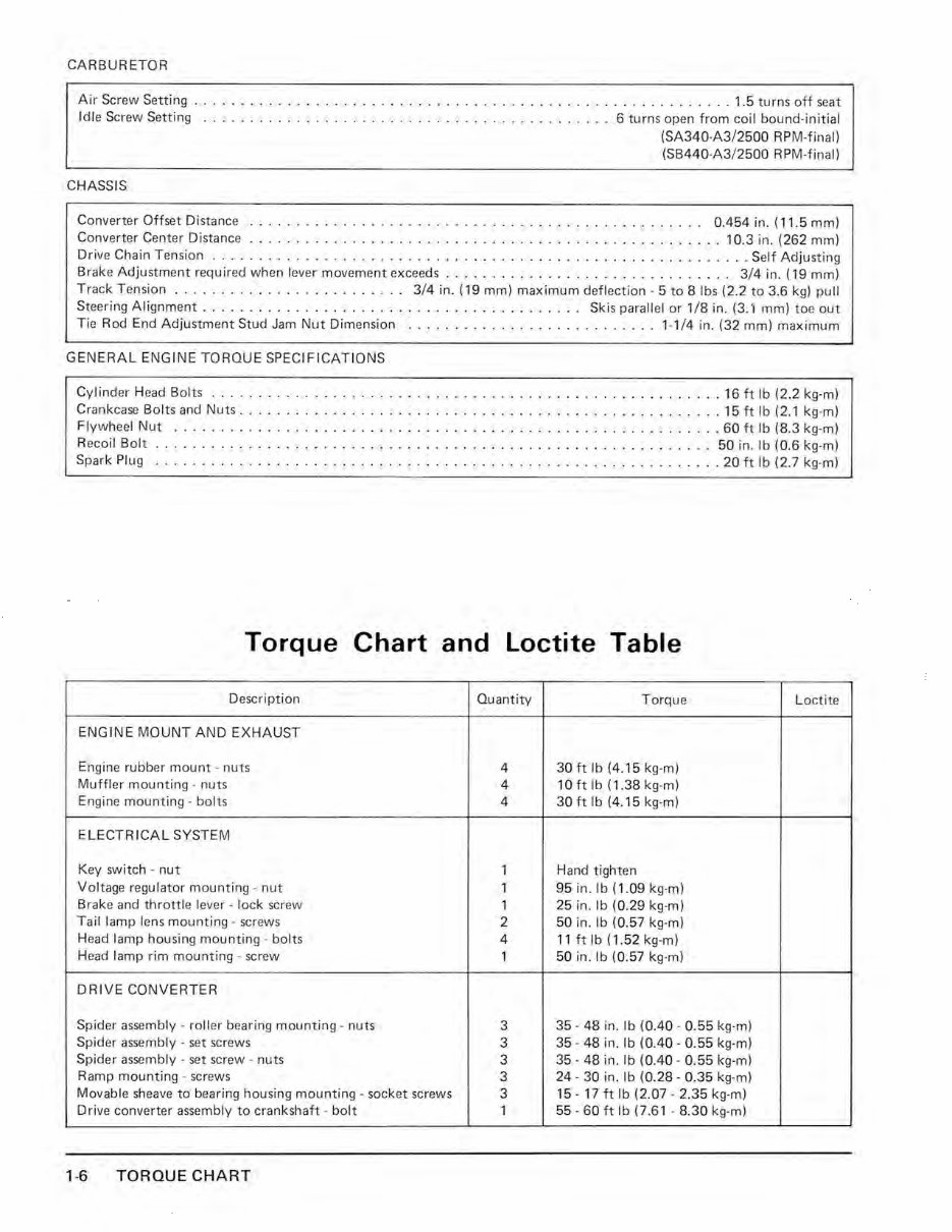
CARBURETOR Air Screw Setting .. .. .. .. ...... . .. . .. ....... .. . .... . ..... .. ...... . ......... 1.5 turns off seat Idle Screw Setting .. .. .. ... . ... . ... .. .. .. ..... .. .. .. .. ...... .. 6 turns open from coil bound-initial CHASSIS (SA340-A3/2500 RPM-final) (SB440-A3/2500 RPM-final) Converter Offset Distance . .. ...... .. .. ... .. ... . .. .. ... .. ........ .. ... ... .. 0.454 i n. (11.5 mm) Converter Center Distance ... .. .. . .. .. .. ....... ..... .... .. .. ... . .... .. ... .... 10.3 in. (262 mm) Drive Chain Tension . . .. .. . .. .. .... ... .. .... . .. .... ... . .. . .. .. ... .... .. .. . .... Self Adjusting Brake Adjustment required when lever movement exceeds. . . . . . . . . . . . . . . . . . . . . . . . . . . . . .. 3/4 in. (19 mm) Track Tension .. .. ........... .. .. .. .. .. 3/4 in. (19 mm) maximum deflection -5 to 8 Ibs (2.2 to 3.6 kg) pull Steering Alignment ... .. ...... . ........... . .. ... ... ......... Skis parallel or 1/8 in . (3.1 mm) to e out Tie Rod End Adjustment Stud Jam Nut Dim ension ... ... .. . ...... .. .......... 1- 1/4 in. (32 mml maximum GENERAL ENGINE TORQUE SPECIFICATIONS Cylind er Head Bolt s ....... .. .. .. .. .. .. . .. ...... .......... ... .. ... . .. .. .. . . 16 ft Ib (2.2 kg-ml Crankcase Bolts and Nuts .... .... . .. . .... . ... .. ... .. .... .. .. .. ... . .. .. ...... . 15 ft Ib (2.1 kg-ml Flywheel Nut . .. ..... . ... . .... . .. ..... . ... .. . ... ..... .. .. ... ....... ... .. 60 ft Ib (8.3 kg-ml Recoil Bo lt .. ... .. .. .. .. .. .... .. .. . .... .... .. .. .. ..... ... . ............. 50 in. Ib (0.6 kg-ml Spark Plug .. .................... .. ... . ........ .. .. . .......... . .. . ...... 20 ft Ib (2.7 kg-ml Torque Chart and loctite Table Description Quantity Torque Loctite ENGINE MOUNT AND EXHAUST Engine rubber mount - nuts 4 30 ft Ib (4.15 kg-m) Muffler mounting - nuts 4 10 ft Ib (1.38 kg-ml Engine mounting - bolts 4 30 ft Ib (4.15 kg-ml ELECTRICAL SYSTEM Key switch - nut 1 Hand tighten Voltage regulator mounting - nut 1 95 in. lb (1 .09 kg-ml Bra ke and throttle lever - lock screw 1 25 in. Ib (0.29 kg-ml Tail lamp lens mounting - screws 2 50 in. Ib (0.57 kg-ml Head lamp housing mounting - bolts 4 11 ft Ib (1.52 kg-ml Head lamp rim mounting - screw 1 50 in. Ib (0.57 kg-ml DRIVE CONVERTER Spider assembly - roller bearing mounting - nuts 3 35 - 48 in. Ib (0.40 - 0.55 kg-ml Spider assembly - set screws 3 35 - 48 in. Ib (0.40 - 0.55 kg-ml Spider assembly - set screw - nuts 3 35 - 48 in. Ib (0.40 - 0.55 kg-ml Ramp mounting - screws 3 24 - 30 in . Ib (0.28 - 0.35 kg-ml Movable sheave to bearing housing mounting - socket screws 3 15 - 17 ft Ib (2.07 - 2.35 kg-ml D rive converter assembly to crankshaft - bolt 1 55 - 60 ft Ib (7.61 - 8.30 kg-ml 1-6 TORQUE CHART
This manual is a comprehensive guide for the 1979 KAWASAKI DRIFTER 340, providing detailed instructions for maintenance and repair tasks. It is a valuable resource for professional mechanics and DIY enthusiasts alike.
With hundreds of pages, this manual covers a wide range of topics, from basic maintenance such as oil changes to more complex procedures like transmission swaps. The manual includes numerous illustrations and easy-to-understand text to assist you throughout the process.
Features:
Step-by-step guidance for maintaining and repairing your Sled
Search function for easy navigation
Printable pages for convenience
By utilizing this Factory Service Repair Manual, owners can gain the knowledge needed to effectively maintain and repair their machine. It provides insights that are typically known by factory-trained technicians, empowering owners to make informed decisions about their vehicle.