2011 TM SHARE OUR PASSION. T TABLE OF CONTENTS 1. General Information/Specifications 2. Engine 3. Engine-Related Items 4. Fuel Systems 5. Electrical Systems 6. Drive Train/Track/Brake Systems 7. Rear Suspension 8. Steering and Body
1-1 1 SECTION 1 — GENERAL INFORMATION/ SPECIFICATIONS TABLE OF CONTENTS General Specifications ............................................ 1-2 Snowmobile Identification........................................ 1-2 Recommended Gasoline and Oil ............................ 1-2 Engine Break-In ...................................................... 1-3 Drive Belt Break-In .................................................. 1-3 Genuine Parts ......................................................... 1-3 High Altitude Operation ........................................... 1-3 Low Oil Pressure Warning Light (4-Stroke) ............. 1-5 Preparation For Storage .......................................... 1-6 Preparation After Storage........................................ 1-7 After Break-In Checkup (100 Miles - 2-Stroke/600 Miles - 4-Stroke) ................................................... 1-7 After Break-In Checkup Checklist ........................... 1-8 Engine Specifications .............................................. 1-9 Cylinder Head Volume Specifications (2-Stroke) .. 1-10 Crankshaft Runout/Repair Specifications (2- Stroke) ........................................................ 1-10 Arctic Power Valve (APV) System Specifications (2-Stroke) ................................................... 1-10 Oil Consumption Specifications (2-Stroke)............ 1-11 EFI Specifications ................................................. 1-11 Throttle Valve Angle Specifications ....................... 1-11 Fuel Pump Specifications (570 cc) ........................ 1-11 Carburetor Specifications (570 cc) ........................ 1-11 Ignition Timing Specifications (2-Stroke) ............... 1-12 Electrical Specifications ........................................ 1-14 Drive System Specifications .................................. 1-18 Drive Clutch/Driven Pulley-Related Specifications ......................................... 1-18 Drive Belt Dimensions ........................................... 1-18 Drive System Components ................................... 1-18 Gear Case Performance Calibrations ................... 1-19 Suspension Specifications .................................... 1-20 Track Specifications............................................... 1-21 Idler Wheel Dimensions ........................................ 1-21 Engine Assembly Schematics/Torque Specifications (Table of Contents) ................ 1-21 Engine Torque Patterns (1100 cc) ......................... 1-34 Torque Specifications ............................................ 1-35 Manual Table of Contents
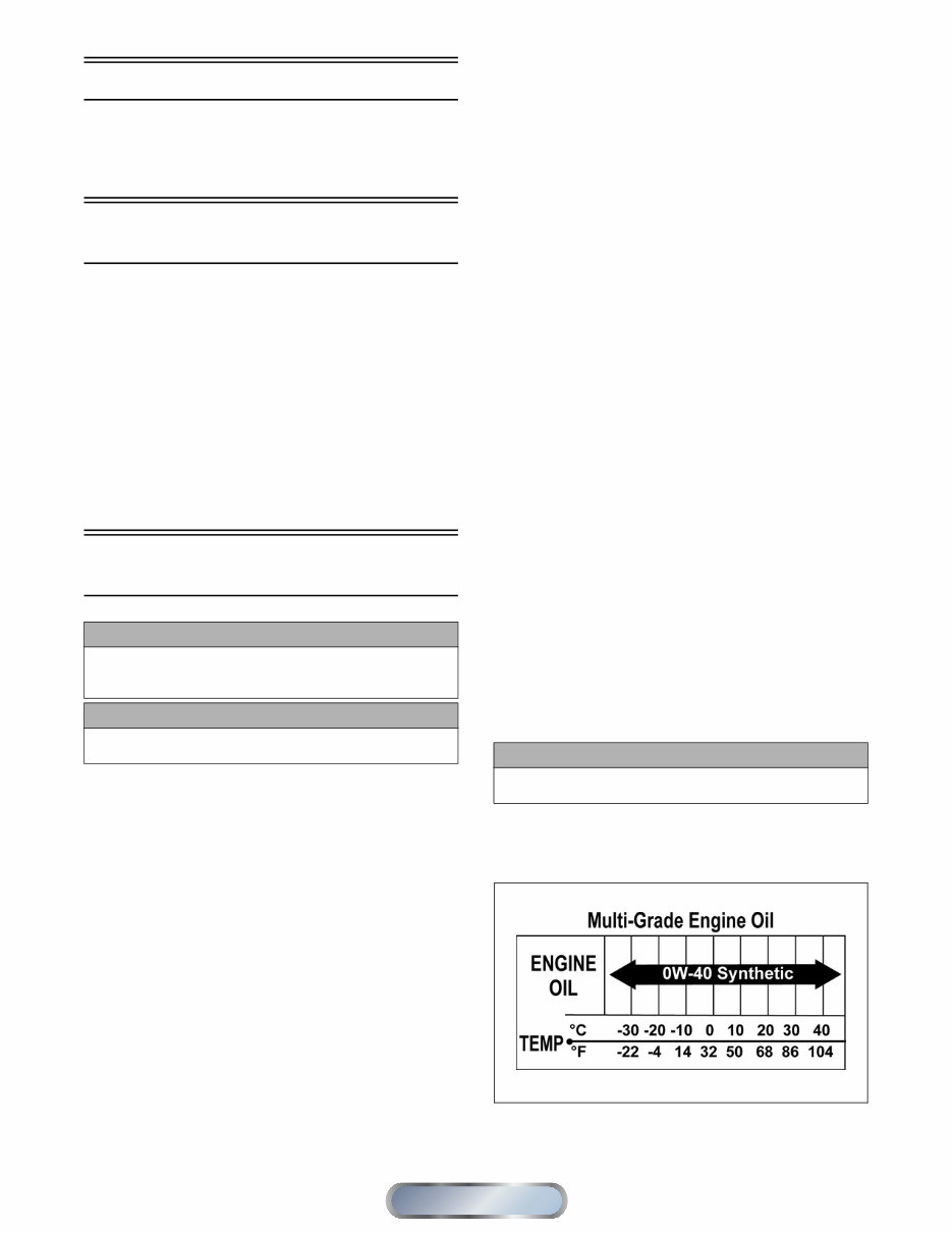
1-2 General Specifications NOTE: General specifications for each 2011 Arctic Cat Snowmobile can be accessed from the Arctic Cat Cat Tracker Dealer Communication System online. Snowmobile Identification The Arctic Cat Snowmobile has two important identifica- tion numbers. The Vehicle Identification Number (VIN) is stamped into the tunnel near the right-side footrest. The decal also displays pertinent production information. The Engine Serial Number (ESN) is stamped into the crankcase of the engine. NOTE: On the Crossfire/M-Series the VIN also appears on a decal beneath the seat. These numbers are required to complete warranty claims properly. No warranty will be allowed by Arctic Cat Inc. if the engine serial number or VIN is removed or muti- lated in any way. Recommended Gasoline and Oil RECOMMENDED GASOLINE (570 cc) The recommended gasoline to use in these snowmobiles is 87 octane regular unleaded. NOTE: In many areas, oxygenates (either ethanol or MTBE) are added to the gasoline. Oxygenated gaso- lines containing up to 10% ethanol or up to 15% MTBE are acceptable gasolines; however, whenever using oxygenated gasolines, the carburetor main jet must be one size larger than the main jet required for regular unleaded gasoline. For example, if a 220 main jet is recommended for regular unleaded gasoline, a 230 main jet must be installed if using an oxygenated gasoline. When using ethanol blended gasoline, adding a gasoline antifreeze is not necessary since ethanol will prevent the accumulation of moisture in the fuel system. RECOMMENDED GASOLINE (500/600/1000/1100 cc Non-Turbo) The recommended gasoline to use in these snowmobiles is 87 octane regular unleaded. In many areas, oxygenates (either ethanol or MTBE) are added to the gasoline. Oxy- genated gasolines containing up to 10% ethanol or up to 15% MTBE are acceptable gasolines. Do not use gaso- lines containing methanol. NOTE: On the 500/600/1000 cc models for optimum performance, do not exceed the recommended 87 octane gasoline. Using a higher octane gasoline will not increase overall performance. RECOMMENDED GASOLINE (800/1100 cc Turbo) The recommended gasoline to use in these snowmobiles is 91 octane (minimum). NOTE: If a situation arises wherein 91 octane gaso- line is not available, 87 octane gasoline can be substi- tuted; however, do not prolong the usage of 87 octane gasoline as it will cause poor engine performance. In many areas, oxygenates (either ethanol or MTBE) are added to the gasoline. Oxygenated gasolines containing up to 10% ethanol or up to 15% MTBE are acceptable gasolines. Do not use gasolines containing methanol. RECOMMENDED OIL (2-Stroke) The recommended oil to use in the oil-injection system is Arctic Cat Formula 50 Injection Oil for 500/570 cc mod- els (p/n 5639-475 - qt) or (p/n 5639-476 - gal.) or either Arctic Cat APV Synthetic 2-Cycle Oil (p/n 4639-349 - qt) or (p/n 5639-469 - gal.) or Forumla SS Semi-Syn- thetic Oil (p/n 5639-470 - qt) or (p/n 5639-471 - gal.) for 600/800/1000 cc models. These oils are specially formu- lated to be used either as an injection oil or as a pre-mix oil (for break-in) and meets all of the lubrication require- ments of the Arctic Cat snowmobile engine. RECOMMENDED OIL (4-Stroke) The recommended oil to use is Synthetic 0W-40 Oil in all temperatures and conditions. OILCHARTJ After the engine break-in period, the engine oil should be changed every 2500-3000 miles (non-turbo) or 1500- 2000 miles (turbo) and before prolonged storage. CAUTION Do not use white gas or gasolines containing methanol. Only Arctic Cat approved gasoline additives should be used. CAUTION Any oil used in place of the recommended oil may cause serious damage. CAUTION Any oil used in place of the recommended oil could cause serious engine damage. Manual Table of Contents
1-3 1 Engine Break-In 2-STROKE The Arctic Cat 2-stroke engine (when new or rebuilt) requires a short break-in period before the engine is sub- jected to heavy load conditions. Arctic Cat requires that the first tankful of fuel be premixed at a 100:1 ratio in all oil-injection models. During the break-in period, a maximum of 1/2 throttle is recommended; however, brief full-throttle accelerations and variations in driving speeds contribute to good engine break-in. 4-STROKE The Arctic Cat 4-stroke engine (when new or rebuilt) requires a short break-in period before the engine is sub- jected to heavy load conditions. This engine does not require any pre-mixed fuel during the break-in period. To ensure trouble-free operation, careful adherence to the following break-in guidelines will be beneficial. * With occasional full-throttle operation. To ensure proper engine break-in, Arctic Cat recom- mends that the engine oil and filter be changed after 500 miles or after one month, whichever comes first. This service is at the discretion and expense of the snowmo- bile owner. Drive Belt Break-In Drive belts require a break-in period of approximately 25 miles. Drive the snowmobile for 25 miles at 3/4 throttle or less. By revving the engine up and down (but not exceed- ing 60 mph), the exposed cord on the side of a new belt will be worn down. This will allow the drive belt to gain its optimum flexibility and will extend drive belt life. NOTE: Before starting the snowmobile in extremely cold temperatures, the drive belt should be removed and warmed up to room temperature. Once the drive belt is at room temperature, install the drive belt (see Drive Belt sub-section in Section 6 of this manual). Genuine Parts When replacement of parts is necessary, use only genuine Arctic Cat parts. They are precision-made to ensure high quality and correct fit. High Altitude Operation Operating a snowmobile at varying altitudes requires changes in performance components. These changes affect drive train components and carburetion compo- nents. NOTE: The 1100 cc turbo does not require calibra- tion changes for varying altitudes. High altitude information decal(s) are located beneath the hood of the snowmobile on the Crossfire/M-Series and on the belt guard on the remaining models. The M-Series snowmobiles are initially set up at the fac- tory for operation between 6000-9000 feet. Consult the appropriate specifications for this information. Following are basic high altitude theories for clutching, engine, suspension, and track. CLUTCHING As altitude changes, engine horsepower changes with it. As you go up in altitude, the engine loses horsepower. Because of this, the constant velocity transmission (CVT) system needs to be changed to compensate for the horsepower loss. At altitudes above 5000 ft, clutch engagement RPM is normally higher than the standard setting due to the horsepower loss at altitude as opposed to what would be seen for horsepower at sea level. The engine will lose peak horsepower but will also lose horsepower at engagement speed. For this reason, higher engagement speeds are usually needed at altitude in order to attain acceptable acceleration. This higher engagement speed can be attained several ways. Some of the methods will affect other characteristics of CVT operation, so you must be careful what you change. Drive clutch springs are the most common way to increase engagement speed; however, by simply changing the cam arms to a lighter weight from the heavier sea level cam arm, you will gain some engagement speed. CAUTION DO NOT exceed the one (1) tankful limitation of a 100:1 gas/oil break-in mixture. Continuous use of a gas/oil mixture, unless consistently operating in extremely cold conditions (-26°C/-15°F or colder), could cause spark plug fouling and excessive carbon buildup. CAUTION DO NOT use premixed fuel in the snowmobile gas tank. Engine damage will occur. 0-200 miles 1/2 Throttle (45 MPH-max) 200-400 miles 1/2-3/4 Throttle 400-600 miles 1/2-3/4 Throttle * CAUTION Never run the engine with the drive belt removed. Excessive revving of the engine could result in serious engine damage and drive clutch failure. CAUTION On the 570 cc, carefully follow the Carburetor Jet Chart recommendations for proper carburetor calibration for altitude, temperature, and gasoline being used. Manual Table of Contents
1-4 Other more complicated methods exist such as engage- ment notches and changing the position of the cam arm center of gravity in relation to the roller. This is called “tucking the weight” and can be used, but, like the engagement notch, it can hurt belt life. The driven clutch will also play a part in CVT tuning for high altitude operation. A steeper helix (torque bracket) angle in the driven clutch will mean a quicker up-shift. A shallower angle will mean a slower up-shift. If the up-shift is too quick, due to a very steep helix, RPM will be pulled down under the peak operating RPM of the engine (where the horsepower is) and performance will suffer. The engine may even bog. If you have a helix that is too shal- low, the engine may over-rev or have poor acceleration. Usually, angles shallower than the sea level calibrations work best. The driven spring will also affect driven clutch tuning. Tighten the spring, and RPM will increase. Loosen the spring, and RPM will decrease. The spring should be used to fine-tune and complement the helix selection. Carburetor calibration changes for high altitude operation will have an effect on the CVT system and how it operates. Under- standing the basics of CVT operation is important in order to make the correct high altitude CVT calibration changes. ENGINE A normally aspirated engine will generate more horsepower at sea level than it does at higher altitudes. Many reasons for this are possible, but the biggest reason is that the higher you go, less oxygen is available for the engine to use during its combustion process. Less oxygen means it needs less fuel to obtain the correct air/fuel ratio to operate properly. This is why the fuel ratio has to be recalibrated. High alti- tude engines operate as though they have a lower compres- sion ratio. This, along with less oxygen and less fuel, means that the engine generates less horsepower. The carbureted models will also have lower pressure applied to the float chamber because of pressure changes in the atmosphere between high altitude and sea level. All of these characteristics will become more evident the higher the altitude. It will be necessary to make changes to the fuel systems (carbureted models) and drive systems that support engine operation as altitude changes. TURBOCHARGING Turbocharging is one method of compensating for loss of air density that works extremely well when applied to four-cycle internal combustion engines. Exhaust gasses are directed through the turbocharger tur- bine wheel which is attached to the compressor through a common shaft. As the exhaust gasses spin the turbine, the compressor is spun at very high RPM. Inlet air is drawn into the compressor, compressed, and routed to the intake mani- fold of the engine. Intake pressure, therefore, is maintained at the optimum level as altitude or temperature increases. The turbocharger output must be regulated to maintain the optimum manifold pressure throughout the designed operat- ing range. This is accomplished by regulating the volume of exhaust gasses passing through the turbine by controlling a diverter valve (waste-gate) at the turbocharger turbine inlet. At lower altitudes/temperatures, excessive exhaust gasses are diverted past the turbine and into the exhaust down- stream of the turbocharger thus limiting the compressor out- put to maintain correct manifold pressure. As altitude increases, the manifold pressure is held con- stant by diverting less exhaust past the turbine, thus increasing compressor speed. This will continue until the waste-gate is completely closed at which time manifold pressure will start to decrease much the same as a nor- mally aspirated engine. The waste-gate is controlled by a spring/diaphragm mechanism that is connected to the intake manifold by an air line. A mechanical linkage connects the diaphragm to the waste-gate control arm. Air is heated by friction and compression through the tur- bocharger and air density is lost by heating the air; there- fore, an after-cooler is installed between the turbocharger compressor and the intake manifold. This is an air-to-air after-cooler that uses outside air directed through a radia- tor-type cooler to cool the compressed air prior to enter- ing the intake manifold. SUSPENSION The different riding styles of the individual operator, the varying snow conditions, and the type of terrain are all factors that affect the suspension at high altitude. Trail riding versus powder snow riding versus combination riding will all require different suspension settings. The normal setting for front ski suspension is as little spring pre-load tension as possible for powder snow rid- ing allowing the skis to float across the snow with the least amount of resistance. Trail riding will require more spring tension to carry the varying load more effectively. Many different settings and spring tensions to consider exist when adjusting for riding style and snow condi- tions. The rear suspension has a number of spring settings that produce different riding characteristics. The front arm spring and shock will also affect the ride and handling when either on a trail or in powder snow. A strong spring setting on this shock will cause the snow- mobile to tend to “dig” more when riding in the powder snow rather than climbing up on top of the snow. But, it will work more effectively when riding on a trail. A softer spring setting will allow the front of the rear sus- pension to collapse much quicker and change the angle of the track to the snow. A more gradual angle will tend to raise the snowmobile up on the snow rather than digging into it. Many possible variables and adjustments to the rear sus- pension exist depending on snow conditions, riding style, and type of terrain. These adjustments can be made to individualize the snowmobile to the riding style of the operator. Manual Table of Contents
1-5 1 M-Series/Crossfire As snow cover and riding conditions change, several dif- ferent adjustments can be made to change the ride and han- dling characteristics for operator preference. Located on the front suspension arm are limiter straps. They limit the amount of “fallout” the front arm can have. These straps may be adjusted in or out due to conditions and riding style. The more the straps are brought up, the more steering power the operator has due to the amount of ski pressure. Another adjustment that can be made on the rear suspen- sion is the front arm shock spring tension. As trail condi- tions change, the spring pre-load may be used to decrease the chance of the front end “bottoming out.” With a stiffer spring pre-load, the ride of the snowmobile will improve on the trail but will affect the performance in the deep powder snow. In deep powder snow, the stiffer spring pre-load will cause the front-end to “dig” and pos- sibly take longer for it to plane off. Several different-rate springs are available for different riding styles and terrain conditions. On the standard models, the front shock springs are also individually adjustable for the terrain conditions and driving style of the operator. The spring adjuster has been set at the factory so the correct amount of threads are exposed between the spring adjuster and the shock hous- ing as an initial setting. Additional ski pressure can be obtained by tightening the spring tension; ski pressure can be decreased by relaxing spring tension. Springs with different spring rates are available for operator choice and snow conditions. A limit exists as to how far you can pre-load the springs before “coil bind” takes effect where the wire on the spring actually runs into itself and causes binding. Equal adjustments should be maintained on both sides of the snowmobile. On the Sno Pro models with air shocks, they are individually adjustable for the terrain conditions and driving style of the operator. The shocks are preset at the factory (see chart) as an initial setting; however, it is possible to “fine tune” the shocks to match the operator’s weight, riding style, and terrain conditions. Checking and adjusting air pressure must be done at rid- ing temperature (outside). Also, it is advisable to check air pressure when the outside temperature varies more than 25°. NOTE: Care should be taken to have equal pressure in the ski shocks before operating the snowmobile. Finally, track tension should be looked at to make sure that it is within recommended specifications to affect the efficiency of the snowmobile. On models with the torque sensing link, the track is actually tightening as the sus- pension moves through its range of motion causing the track to sag in the middle and rub on the top part of the rear suspension arm. TRACK Carefully matching the riding requirements to the type of track will ensure the maximum use of all available engine power. Lug height and track durometer are the two main concerns when selecting a track for various riding styles. Tracks exist with lug heights from 0.750” up to 2.25” to accommodate various snow conditions. Generally, the deeper the snow, the taller the lug. It must be noted that the installation of any deep-lug track may reduce top end speed and promote premature wear strip wear in marginal snow conditions. Durometer is a measurement of how hard a rubber is. The lugs on most tracks range between 60 and 80 durometer. On the durometer scale, the higher the number, the harder the lugs. For riding in deep powder snow, a softer 60 durometer track works best. The softer rubber allows the track to “give” a little and pack the snow creating lift rather than digging its way straight down. When hill- climbing, the harder lug of an 80 durometer track works the best due to penetrating the hard snow creating more bite. Some tracks come with a dual durometer rating, such as a track with a 80/60 durometer rating. The lugs on this track are 80% 80 durometer rubber, and the top 20% is made of the softer 60 durometer rubber. This track is designed to be a good all-around track for riding mostly in deep powder snow but can climb the occasional hard snow hill. Low Oil Pressure Warning Light (4-Stroke) The Low Oil Pressure Warning Light indicates engine oil pressure, not the oil level; however, if the oil level is low, it may affect oil pressure. The light should illuminate each time the ignition switch is turned to RUN or START, and it should go out when the engine starts. If the light stays illuminated or it illuminates while the engine is running, oil pressure has been lost and the engine will automatically shut off. NOTE: The following oil check procedures are valid only if the oil pressure warning light has activated. If oil pressure is lost, use the following procedure: 1. With the engine off, remove the engine oil level stick and wipe it clean. Without screwing it in, set the stick back in the oil tank. Remove it and observe the oil level on the stick. NOTE: To ensure an accurate reading, the snowmo- bile should be on level ground. 2. If the oil level is at or below the ADD mark on the oil level stick, add only enough recommended oil to raise the level to the NORMAL range. DO NOT overfill the reservoir with oil. 3. After adding oil if the engine starts, oil pressure should be normal. Initial Setting Chart Model Front Shock (Ski) Rear Arm Shock F-Series/Z1 Sno Pro 5.3 kg/cm 2 (75 psi) N/A Crossfire Sno Pro 4.6 kg/cm 2 (65 psi) 9.5-10.2 kg/cm 2 (135-145 psi) M-Series Sno Pro 4.2 kg/cm 2 (60 psi) 9.5-10.2 kg/cm 2 (135-145 psi) Manual Table of Contents
1-6 Preparation For Storage Prior to storing the snowmobile, it must be properly ser- viced to prevent corrosion and component deterioration. To prepare the snowmobile for storage, Arctic Cat rec- ommends the following procedure: 1. Clean the seat cushion with a damp cloth and Arctic Cat Vinyl Protectant. 2. Clean the snowmobile thoroughly by hosing dirt, oil, grass, and other foreign matter from the skid frame, tunnel, hood, and belly pan. Allow the snowmobile to dry thoroughly. DO NOT get water into any part of the engine. 3. On the 4-stroke models, change the engine oil. 4. Add Arctic Cat Fuel Stabilizer to the gas tank fol- lowing directions on the container for the stabilizer/ gasoline ratio. Tighten the gas tank cap securely. 5. On the 570 cc, carefully pry the intake boots partially over the carburetor inlets. 6. On the 2-stroke models, place the rear of the snow- mobile up on a shielded safety stand; then start the engine and allow to idle. With the engine idling, pry the intake boot forward; then spray an Engine Stor- age Preserver into the intakes until the engine exhaust starts to smoke heavily or until the engine starts to drop in RPM. Turn engine off. Install the intake boots (570 cc). 7. Plug the exhaust system outlet with a clean cloth. 8. On the 2-stroke models with the ignition switch in the OFF position: A. Disconnect the high tension leads from the spark plugs; then remove the plugs, connect them to the leads, and ground them on the cylinder heads. B. Pour 29.5 ml (1 fl oz) of SAE #30 petroleum- based oil into each spark plug hole and pull the recoil starter handle slowly about 10 times. C. Install the spark plugs and connect the high ten- sion leads. 9. On the 570 cc, drain the gas from each carburetor float chamber. 10. Drain the gas tank; then flush the gear case and change the lubricant (see Section 6). 11. Remove the drive belt from the drive clutch/driven pulley (see Section 6). Lay the belt on a flat surface or slide it into a cardboard sleeve to prevent warping or distortion during storage; then clean and inspect the drive clutch and driven pulley. 12. Apply light oil to the shafts of the shock absorbers; then lubricate all grease fittings (front and rear sus- pension, spindles, and upper steering shafts on the Crossfire/M-Series or steering arms on the Bearcat/ F-Series/Z1/T-Series) with an all-temperature grease. 13. Tighten all nuts, bolts, and cap screws making sure all calibrated nuts, bolts, and cap screws are tight- ened to specifications. Make sure all rivets holding the components together are tight. Replace all loose rivets. 14. Clean and polish the hood, console, and chassis with Arctic Cat Hood and Windshield Cleaner/ Polish. DO NOT USE SOLVENTS OR SPRAY CLEAN- ERS. THE PROPELLENT WILL DAMAGE THE FINISH. 15. On electric start models, disconnect the battery cables making sure to disconnect the negative cable first; then clean the battery posts and cables. 16. If possible, store the snowmobile indoors. Raise the track off the floor by blocking up the back end mak- ing sure the snowmobile is secure. Loosen the track adjusting bolts to reduce track tension. Cover the snowmobile with a machine cover or a heavy, venti- lated tarpaulin to protect it from dirt and dust. 17. If the snowmobile must be stored outdoors, position the snowmobile out of direct sunlight; then block the entire snowmobile off the ground making sure the snowmobile is secure. Loosen the track adjusting bolts to reduce track tension. Cover with a machine cover or a heavy, ventilated tarpaulin to protect it from dirt, dust, and rain. CAUTION Do not run the engine without the belt guard in place and secured. CAUTION Never crank the engine over without grounding the spark plugs. Damage to ignition system may result. CAUTION Batteries require charging if left for extended non-start periods. Arctic Cat recommends trickle charging once a month. Follow the manufacturer’s instructions and cau- tions. CAUTION On models with remote start, make sure to leave the battery cables disconnected. Failure to disconnect the battery cables when storing the snowmobile for a pro- longed period of time (six weeks or more) will result in a discharged or damaged battery. CAUTION Avoid storing in direct sunlight and using a plastic cover as moisture may collect on the snowmobile caus- ing corrosion. Manual Table of Contents
1-7 1 Preparation After Storage Taking the snowmobile out of storage and correctly pre- paring it for another season will assure many miles and hours of trouble-free snowmobiling. Arctic Cat recom- mends the following procedure: 1. Clean the snowmobile thoroughly. Polish the exte- rior of the snowmobile. 2. Clean the engine. Remove the cloth from the exhaust system. Check exhaust system and air silencer for obstructions. On the turbo models, inspect the air fil- ter and replace as necessary. 3. Inspect all control wires and cables for signs of wear or fraying. Replace if necessary. Use cable ties or tape to route wires and cables away from hot or rotat- ing parts. 4. Remove and inspect the drive belt for cracks and tears. Check belt specifications. Replace if damaged or worn. Install the drive belt (see Section 6). NOTE: If the old belt is worn but in reasonable con- dition, retain it with the snowmobile as a spare in case of emergency. 5. On the 570 cc, inspect the in-line fuel filter and replace if necessary; then adjust the carburetors and choke cable. 6. Inspect all fuel hoses and oil hoses for deterioration or cracks; replace if necessary. Make sure all connec- tions are tight. 7. On the 2-stroke models, fill the oil-injection reser- voir with the recommended injection oil; then inspect each spark plug. Replace, gap, or clean as necessary. NOTE: On the 2-stroke models after prolonged stor- age, Arctic Cat recommends one tankful of 100:1 gas/ oil mixture be used in conjunction with the oil-injec- tion system to ensure proper lubrication. 8. Adjust the throttle cable. 9. Tighten all nuts, bolts, and cap screws making sure all calibrated nuts, bolts, and cap screws are tight- ened to specifications. 10. If not done during preparation for storage, lubricate all grease fittings (front and rear suspension, spin- dles, and upper steering shafts on the Crossfire/M- Series or steering arms on the Bearcat/F-Series/Z1/T- Series) with an all-temperature grease. 11. On liquid cooled models, check the coolant level and all coolant hoses and connections for deterioration or cracks. Add properly mixed coolant as necessary. 12. On fan cooled models, clean the engine cooling fins and all shrouding. 13. On electric start models, charge the battery; then connect the battery cables making sure to connect the positive cable first. Test the electric start system. 14. Inspect the entire brake system, all controls, head- light, taillight, brakelight, ski wear bars, and head- light aim; adjust or replace as necessary. 15. Adjust the track to the proper tension and alignment. Lock the jam nuts. 16. Fill the gas tank with fresh, clean gas. After Break-In Checkup (100 Miles - 2-Stroke/600 Miles - 4-Stroke) Certain areas require adjustment after the break-in period in order to obtain peak performance. These areas are the following. CARBURETOR JETTING (570 cc) — Altitude, tem- perature, and the use of oxygenated gasoline affect the carburetion needed for optimum engine performance. The carburetor main jets must be changed in conjunction with changes in operating altitude, oxygenated gasoline usage, and temperature. DRIVE BELT DEFLECTION — Drive belt deflection is very important to the snowmobile. Even if it is checked and is correct when the snowmobile is set up, it does change (more so during the break-in period). This is because the rubber engine mounts and the rubber snubber on the torque link will all take a “set” during the first 100 miles allowing the distance between the drive clutch and driven pulley to shorten. When this happens, the snow- mobile will appear to have a too long drive belt. To add to this, the drive belt itself wears and stretches somewhat leading to a low-end performance problem and, if not corrected, causes premature drive belt wear. After the break-in period, drive belt deflection should be checked according to the instructions given in Section 6 of this manual. DRIVE BELT BREAK-IN — Drive belts require a break-in period of approximately 25 miles. Drive the snowmobile for 25 miles at 3/4 throttle or less. By rev- ving the engine up and down (but not exceeding 60 mph), the exposed cord on the side of a new belt will be worn down. This will allow the drive belt to gain its optimum flexibility and will extend drive belt life. CAUTION On the 570 cc if the gas in each carburetor float cham- ber was not drained prior to storage, the carburetors must be cleaned before starting the engine. ! WARNING Be sure to tighten the swivel adapter jam nuts securely. If a jam nut isn’t tightened, the adjuster can rotate out of the carburetor cap causing the piston valve not to return to the full-closed position. Manual Table of Contents
1-8 NOTE: Before starting the snowmobile in extremely cold temperatures, the drive belt should be removed and warmed up to room temperature. Once the drive belt is at room temperature, install the drive belt. DRIVE CLUTCH/DRIVEN PULLEY ALIGNMENT — The parallelism and the offset between the drive clutch and driven pulley are set at the factory. Normally, no adjustment is necessary; however, if prema- ture drive belt wear or poor performance is experienced, the drive clutch/driven pulley alignment must be checked. TRACK TENSION AND ALIGNMENT — A certain amount of stretch occurs on all tracks during the first 500 miles. The track must be adjusted after the first 50 to 100 miles to the specifications given in the Track Specifica- tions sub-section of this section and periodically thereaf- ter. If these adjustments aren’t performed, the track may “derail” which leads to track and slide rail damage. Along with these major areas, other areas should be checked and adjusted during the “After Break-In Checkup.” A checklist to assist you with this service follows. After Break-In Checkup Checklist Below is a recommended list of items to check after the break-in period. The recommended mileage for this inspection is between 100 and 300 miles. Jet carburetors according to average tempera- ture, type of gasoline being used, and altitude (570 cc) Check drive belt deflection - drive clutch/driven pulley alignment and parallelism (800/1000/ 1100 cc) Adjust track tension and alignment Check throttle cable tension Check oil-injection pump adjustment (2-stroke) Check engine idle Check coolant level Check gear case lubricant level Check engine oil (4-stroke) Check lights (high/low beam, brakelight) Check safety switch operation Check engine compartment for any rubbing components Check steering hardware for tightness Check skid frame and A-arm mounting hard- ware for tightness Check brake lever travel and adjustment Grease all lubrication points CAUTION Never run the engine with the drive belt removed. Excessive revving of the engine could result in serious engine damage and drive clutch failure. Manual Table of Contents
1-9 1 Engine Specifications 2-Stroke 4-Stroke ITEM 500 cc 570 cc 600 cc 800 cc 1000 cc Engine Model Number AX50L9 AA56A9 AJ60L7 AB80L4 AB10L4 Displacement 499 cc 565 cc 599 cc 794 cc 999 cc No. of Cylinders 2 2 2 2 2 Bore x Stroke 71 x 63 73.8 x 66 73.8 x 70 85 x 70 90.3 x 78 Compression Ratio 6.38:1 6.41:1 6.46:1 6.62:1 6.41:1 Cooling System Liquid Fan Liquid Liquid Liquid Ignition Timing (Engine Warm) 13° @ 2000 RPM 0.040" 20° @ 2000 RPM 0.099" 15° @ 2000 RPM 0.059" 16° @ 2000 RPM 0.0675” 14° @ 1800 RPM 0.057" Spark Plug (NGK) BR9EYA BR9EYA BR9EYA BR9EYA BR9EYA Spark Plug Gap 0.028-0.031" 0.028-0.031" 0.028-0.031" 0.028-0.031" 0.028-0.031" Piston Skirt/Cylinder Clearance 0.0030-0.0041" 0.0031-0.0041" 0.0030-0.0041" 0.0041-0.0053" 0.0030-0.0041" Piston Ring End Gap 0.008-0.016" 0.012-0.0196" 0.012-0.0196" 0.012-0.0196" 0.012-0.0196" Cylinder Trueness Limit 0.004" 0.004" 0.004" 0.004" 0.004" Piston Pin Diameter 0.8659-0.8661" 0.7085-0.7087" 0.8659-0.8661" 0.8659-0.8661" 0.9447-0.9449" Piston Pin Bore Diameter 0.8661-0.8665" 0.7087-0.7091" 0.8661-0.8665" 0.8661-0.8665" 0.9450-0.9453" Connecting Rod Small End Bore 1.0631-1.0634" 0.9056-0.9059" 1.0631-1.0634" 1.0631-1.0634" 1.1418-1.1422" Connecting Rod Radial Play 0.0001-0.0008" 0.0001-0.0008" 0.0001-0.0008" 0.0001-0.0008" 0.0001-0.0008" Crankshaft Runout (t.i.r.) 0.002" 0.002" 0.002" 0.002" 0.002" Crankshaft End Play 0.002-0.004" 0.002-0.004" 0.002-0.004" 0.002-0.004" 0.002-0.004" Reed Stopper Height 0.315" 0.236" 0.433" 0.512" 0.512" ITEM 1100 cc Engine Model Number (Non-Turbo) (Turbo) AA11L5 AB11L5 Displacement 1056 cc No. of Cylinders 2 Bore x Stroke 98 x 70 Cooling System Liquid Spark Plug (NGK) MR8AI-9 Spark Plug Gap 0.031-0.035" Piston Skirt/Cylinder Clearance (Non-Turbo) (Turbo) 0.0011-0.0016" 0.0006-0.0010" Piston Pin Diameter (Non-Turbo) (Turbo) 0.8658-0.8661" 0.9447-0.9449" Piston Pin Bore Diameter (Non-Turbo) (Turbo) 0.8662-0.8664" 0.9449-0.9451" Piston Pin/Connecting Rod (Non-Turbo) Small End Clearance (Turbo) 0.0004-0.0010" 0.0004-0.0009" Piston Ring End Gap (1st) (2nd) (Oil) 0.0059-0.0138" 0.0118-0.0177" 0.0078-0.0275" Piston Ring/Groove Clearance (1st - Top) (1st - Bottom) (2nd) (Oil) 0.0059-0.0074" 0.0008-0.0035" 0.0008-0.0024" 0.0024-0.0059" Piston Diameter (Non-Turbo) (10 mm from skirt edge) (Turbo) 3.8568-3.8574" 3.8574-3.8580" Cylinder/Head Distortion (max) 0.002" Connecting Rod Small End Bore (Non-Turbo) Inside Diameter (Turbo) 0.866-0.867" 0.945-0.946" Cam Lobe Height (Int) (Non-Turbo) (Turbo) 1.487-1.489" 1.436-1.437" Cam Lobe Height (Exh) (Non-Turbo) (Turbo) 1.432-1.433" 1.417-1.418" Camshaft Journal Outside Diameter 0.8650-0.8658" Camshaft Journal Bore Diameter 0.8666-0.8670" Camshaft Journal Clearance 0.0007-0.0020" Crank Pin Diameter 1.7707-1.7720" Crankshaft Runout 0.002" Crankshaft Main Bearing Clearance 0.0006-0.0016" Crankshaft Thrust Runout (max) 0.0043" Crankshaft Main/Rod Journals (Bearing Surfaces) 0.0012" Valve Guide Inside Diameter 0.2165-0.2170" Valve Guide/Stem Clearance (max) (Int) (Exh) 0.0015" 0.0022" Valve Face Width 0.0197" Valve Clearance - Cold (59°-77° F) (Int) (Exh - Non-Turbo) (Exh - Turbo) 0.0039-0.0078" 0.0078-0.0118" 0.0118-0.0157" Valve Seat Contact Width (Int/Exh) 0.0354-0.0433" Valve Stem Diameter (Int) (Exh) 0.2155-0.2161" 0.2147-0.2153" Manual Table of Contents
You are purchasing a comprehensive Service & Shop manual for an Arctic Cat 2011 TZ1. This manual contains technical information useful for both professional mechanics and DIY enthusiasts. It covers a wide range of topics including body and exterior, electrical and electronic systems, audio/video devices, charging system, electrical supply system, gauges and meters, ignition system, lighting and signaling systems, sensors, starting system, switches, wiring harnesses, miscellaneous topics, powertrain and chassis, engine components and parts, engine cooling system, engine oil system, exhaust system, fuel supply system, fuel suspension and steering systems, transmission system, and wheels and tire parts.
This service manual is an invaluable resource as it provides detailed instructions with numerous illustrations to guide you through various maintenance and repair procedures, from simple tasks like an oil change to more complex tasks like a transmission swap. The manual is designed to be user-friendly with easy-to-read text and a search function that allows you to quickly find the information you need. With a file size of 92MB and 531 pages, this manual is available in English format and offers the convenience of printing out specific pages as required.
When you purchase a service manual from us, you can be assured of its excellent quality and our commitment to providing great customer service. This manual is an essential tool for anyone looking to maintain or repair their Arctic Cat 2011 TZ1.