4-1 4 SECTION 4 - FUEL SYSTEMS TABLE OF CONTENTS Fuel System (Carbureted) ....................................... 4-2 Fuel System (Batteryless EFI) .............................. 4-40 Fuel System (Related Items) ................................. 4-67
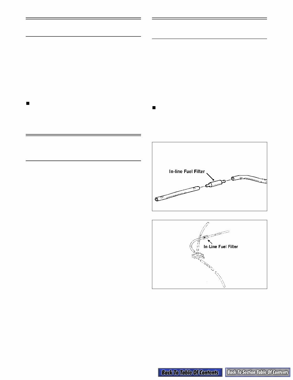
4-2 Fuel System (Carbureted) This sub-section has been organized for servicing car- bureted fuel systems; however, some components may vary from model to model. The technician should use discretion and sound judgment when removing/ disas- sembling and assembling/installing components. Whenever any maintenance or inspection is made on the fuel system in which fuel leakage may occur, there should be no welding, smoking, or open flames in the area. NOTE: Some illustrations and photographs used in this sub-section are used for clarity purposes only and are not designed to depict actual condi- tions. Fuel System (Carbureted) Table of Contents Pre-Maintenance Checks ........................................ 4-2 Changing Main Jet(s)(VM-Style) ............................. 4-3 Changing Main Jets (TM-Style) .............................. 4-4 Carburetor Schematics ........................................... 4-4 Removing Carburetor (BV-Style) ............................. 4-6 Removing Carburetor (VM-Style) ............................ 4-7 Removing Carburetors (TM-Style) .......................... 4-8 Disassembling Carburetor (BV-Style)...................... 4-8 Disassembling Carburetor (VM-Style) ................... 4-10 Disassembling Carburetors (TM-Style) ................. 4-12 Cleaning Carburetor .............................................. 4-14 Inspecting Carburetor............................................ 4-15 Assembling Carburetor (BV-Style) ........................ 4-15 Assembling Carburetor (VM-Style) ....................... 4-16 Assembling Carburetors (TM-Style) ...................... 4-18 Installing Carburetor (BV-Style) ............................. 4-20 Installing Carburetor (VM-Style) ............................ 4-21 Installing Carburetors (TM-Style) .......................... 4-22 Adjusting Carburetor (BV-Style) ............................ 4-23 Adjusting Carburetor(s) (VM-Style) ....................... 4-24 Adjusting Carburetors (TM-Style).......................... 4-28 Throttle Cable (BV-Style) ...................................... 4-29 Throttle Cable (VM-Style)...................................... 4-31 Throttle Cable (TM-Style) ...................................... 4-32 Choke Cable (VM-Style) ....................................... 4-33 Choke Cable (TM-Style) ........................................ 4-34 2002 Carburetor Specifications (Production) ........ 4-35 Mikuni Tuning Components ................................... 4-36 Major Tuning Components .................................... 4-37 Troubleshooting Fuel System (Carbureted) .......... 4-38 Pre-Maintenance Checks Before troubleshooting the fuel system, several simple checks should be performed. Many times what appears to be a serious problem is only a minor one. 1. Make sure the gas tank shut-off valve was in the OPEN position. 2. Turn the shut-off valve to the CLOSED position; then remove the in-line fuel filter. If the filter is dirty, replace the filter. NOTE: Determine which style in-line fuel filter is being replaced and remove and install accord- ingly. 3. Install a new filter making sure the arrow on the filter is directed toward the fuel pump. 735-390A 726-065A
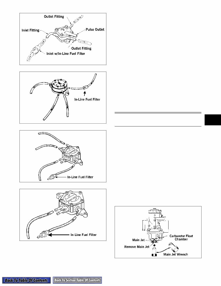
4-3 4 728-272A 725-067A 734-292A 734-292B 4. Check the hoses to ensure that all are correctly connected; then check for cracks. If any cracks are evident in the hoses, replace them making sure none are against any hot or moving parts. Hoses must fit tightly. If hoses do not fit tightly, cut 6 mm (1/4 in.) from the end and install. 5. Check the impulse hose for cracks or any possible air leaks. The hose must fit tightly at both ends. If loose or cracked, replace the hose. 6. Check each carburetor vent hose for kinks or obstructions; remove any obstructions. 7. Check each carburetor float chamber drain hose for water or debris. If seen, clean by removing the plug and draining the drain hose into a small container. 8. Check the gas tank vent hose and fuel hose for obstructions; remove any obstructions. 9. Turn the shut-off valve to the OPEN position. Changing Main Jet(s) (VM-Style) The carburetor main jet(s) must be changed in con- junction with the changes in temperature, altitude, and type of gasoline being used. 1. Loosen each carburetor flange clamp and remove each carburetor from the intake flange and boot. 2. Remove the drain plug and O-ring from each carburetor float chamber and drain the gas into either a small container or an absorbent towel. 3. Using the Main Jet Wrench (p/n 0644-065), thread the main jet out of each carburetor. Account for the baffle ring. Install the new main jet with baffle ring and tighten securely. 4. Install the drain plug and O-ring; then tighten securely. 0728-054 5. Install and secure each carburetor.
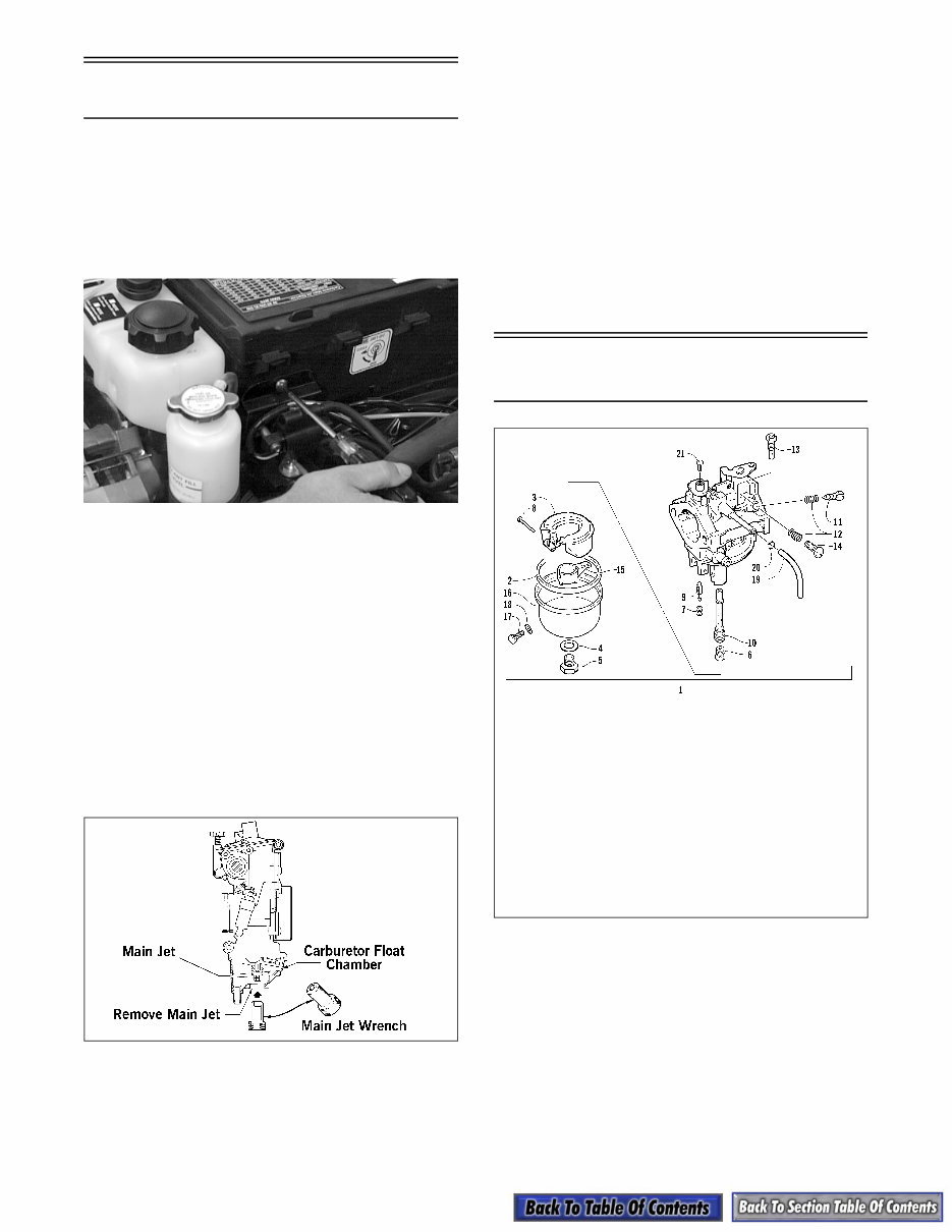
4-4 Changing Main Jets (TM-Style) The carburetor main jets must be changed in conjunc- tion with the changes in temperature, altitude, and type of gasoline being used. 1. Remove the machine screw and washer securing the mounting plate (for the ignition coil and fuel pump) to the air-intake silencer. AN613D 2. Remove the screws securing the air-intake silencer; then move the silencer forward and out of the engine compartment. 3. Loosen the carburetor flange clamps and slide the carburetors out of the intake flanges. Tilt the carburetors forward to access the main jets. 4. Remove the drain plug (with O-ring) from each carburetor float chamber and drain the gas into either a small container or an absorbent towel. 5. Using the Main Jet Wrench (p/n 0644-065), thread the main jet out of each carburetor. Account for the washer. Install the new main jet and washer and tighten securely. 0734-280 6. Install the drain plug with O-ring; then tighten securely. 7. Push the carburetors back into position and into the intake flanges; then tighten the flange clamps. 8. Place the air-intake silencer into position in the engine compartment making sure the carburetors are properly positioned in the boot and secure with the screws. 9. Place the ignition coil/fuel pump mounting plate into position on the air-intake silencer and secure with the machine screw and washer. Carburetor Schematics 0735-414 KEY 1. Carburetor Assy 2. Gasket 3. Float 4. Gasket 5. Drain Plug 6. Main Jet 7. Spring 8. Float Pin 9. Needle Jet 10. Nozzle 11. Adjuster Screw 12. Spring 13. Pilot Jet 14. Screw 15. Ring 16. Float Chamber 17. Drain Screw 18. Gasket 19. Hose 20. Clamp 21. Screw BV-18
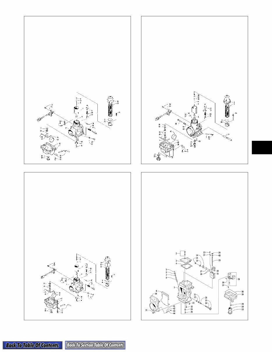
4-5 4 0735-853 0737-025 0736-643 0735-335 KEY 1. Mixing Body Assy 2. Float Chamber 3. Plate 4. Piston Valve 5. Jet Needle 6. Main Jet 7. Baffle Ring 8. Needle Jet 9. E-Clip 10. Float 11. Cap 12. Screw w/Spring Washer 13. Mixing Body Top 14. Pilot Air Screw 15. Spring 16. Spring 17. Idle Speed Screw 18. Drain Screw 19. Washer 20. Float Pin 21. Needle Valve Assy 22. Float Arm 23. Piston Valve Spring 24. Pilot Jet 25. Gasket 26. Starter Plunger Spring 27. Starter Plunger Cap 28. Hose 29. Starter Plunger 30. Screw w/Spring Washer 31. Plate 32. O-Ring 33. Washer 34. Screw w/ Washer 35. Magnet Block 36. Self-Tapping Screw 37. Magnetic Switch 38. Cap 39. Hose Plate VM-32 KEY 1. Mixing Body Assy 2. Float Chamber 3. Plate 4. Piston Valve 5. Jet Needle 6. Main Jet 7. Baffle Ring 8. Needle Jet 9. E-Clip 10. Float 11. Cap 12. Screw w/Spring Washer 13. Mixing Body Top 14. Pilot Air Screw 15. Spring 16. Spring 17. Idle Speed Screw 18. Drain Screw 19. Washer 20. Float Pin 21. Needle Valve Assy 22. Float Arm 23. Piston Valve Spring 24. Pilot Jet 25. Gasket 26. Starter Plunger Spring 27. Starter Plunger Cap 28. Hose 29. Starter Plunger 30. Screw w/Spring Washer 31. Plate 32. O-Ring 33. Washer 34. Screw w/ Washer 35. Magnet Block 36. Self-Tapping Screw 37. Magnetic Switch 38. Cap 39. Plate 40. Washer VM-34 VM-38 KEY 1. Mixing Body Top 2. Piston Valve Spring 3. Plate 4. Jet Needle 5. Piston Valve 6. Needle Jet 7. Screw w/Spring Washer 8. Plate 9. Float Arm 10. Needle Valve Assy 11. Washer 12. Gasket 13. Mixing Body Assy 14. Spring 15. Idle Speed Screw 16. Float Chamber 17. O-Ring 18. Starter Plunger Cap 19. Washer 20. Spring 21. Starter Plunger 22. Air Vent Tube 23. Pilot Air Screw 24. Spring 25. Drain Plug 26. Float Arm Pin 27. Baffle Ring 28. E-Clip 29. Main Jet 30. E-Clip Washer 31. Float 32. Screw Guide 33. Pilot Jet 34. Magnet Block 35. Machine Screw 36. Machine Screw 37. Washer 38. Magnetic Switch 39. Self-Tapping Screw 40. Cap 41. Washer KEY 1. Mixing Body 2. Screw w/ Washer 3. Top Cap 4. Gasket 5. Plunger Cap 6. Guide 7. Spring 8. Starter Plunger 9. Gasket 10. Funnel Assy 11. Screw 12. Screw 13. Plug 14. Plate 15. E-Clip 16. Washer 17. Clip 18. Bushing 19. O-Ring 20. Screw 21. Washer 22. Washer 23. Starter Jet 24. Washer 25. Main Jet 26. Spring 27. Plate 28. E-clip 29. Jet Needle 30. Lever Assy 31. Throttle Valve 32. Pilot Jet 33. Cap 34. Fuel Mixture Screw 35. Float Assy 36. O-Ring 37. Screw 38. O-Ring 39. Float Chamber 40. Washer 41. O-Ring 42. Washer 43. Air Screw 44. Spring TM-36/TM-38 (Triple)
You're Reading a Preview
What's Included?
Lifetime Access
Fast Download Speeds
Offline Viewing
Access Contents & Bookmarks
Full Search Facility
Print one or all pages of your manual
$31.99
1999-2004 ARCTIC CAT SNOWMOBILE All Models Service Repair Manuals (Total 708MB, Searchable, Indexed , Complete FSM Contains
Get your hands on a comprehensive Workshop Service Repair Manual for 1999-2004 Arctic Cat Snowmobiles. This extensive collection includes individual service manuals for specific models, making it an invaluable resource for both professional mechanics and DIY enthusiasts.
The covered models include:
1999-2000 Arctic Cat Snowmobiles
2001 Arctic Cat Snowmobile
2002 Arctic Cat Snowmobile
2003 Arctic Cat Snowmobile
2004 Arctic Cat Snowmobile
The manual covers a wide range of sections, including General Information, Engine, Fuel Systems, Chassis Electrical Systems, Drive Train and Brake Systems, and more. It also contains detailed diagrams, torque specs, and troubleshooting information.
File Format: PDF
Printable: Yes
Delivery: Instant download link available after payment
Requirements: Adobe Reader & WinZip
Ensure you have the right repair manual for your snowmobile to save on repair and maintenance costs. Customer satisfaction guaranteed!
Opt for instant download to save on shipping and get started on your repairs today. Don't hesitate any longer!
Reviews
Q&A
Recently Viewed
5,521,897Happy Clients
2,594,462eManuals
1,120,453Trusted Sellers
15Years in Business
Price:
Actual Price:
1999-2004 ARCTIC CAT SNOWMOBILE All Models Service Repair Manuals (Total 708MB, Searchable, Indexed , Complete FSM Contains