EBS00002 NOTICE This manual was produced by the Yamaha Motor Company primarily for use by Yamaha dealers and their qualified mechanics. It is not possible to include all the knowledge of a mechanic in one manual, so it is assumed that anyone who uses this book to perform maintenance and repairs on Yamaha machine has a basic understanding of the mechanical ideas and the procedures of machine repair. Repairs attempted by anyone without this knowledge are likely to render the machine unsafe and unfit for use. Yamaha Motor Company, Ltd. is continually striving to improve all its models. Modifications and sig- nificant changes in specifications or procedures will be forwarded to all authorized Yamaha dealers and will appear in future editions of this manual where applicable. NOTE: _ Designs and specifications are subject to change without notice. EBS00003 IMPORTANT INFORMATION Particularly important information is distinguished in this manual by the following notations. The Safety Alert Symbol means ATTENTION! BECOME ALERT! YOUR SAFETY IS INVOLVED! Failure to follow WARNING instructions could result in severe injury or death to the machine operator, a bystander or a person checking or repairing the machine. A CAUTION indicates special precautions that must be taken to avoid damage to the machine. A NOTE provides key information to make procedures easier or clearer. WARNING CAUTION: NOTE:
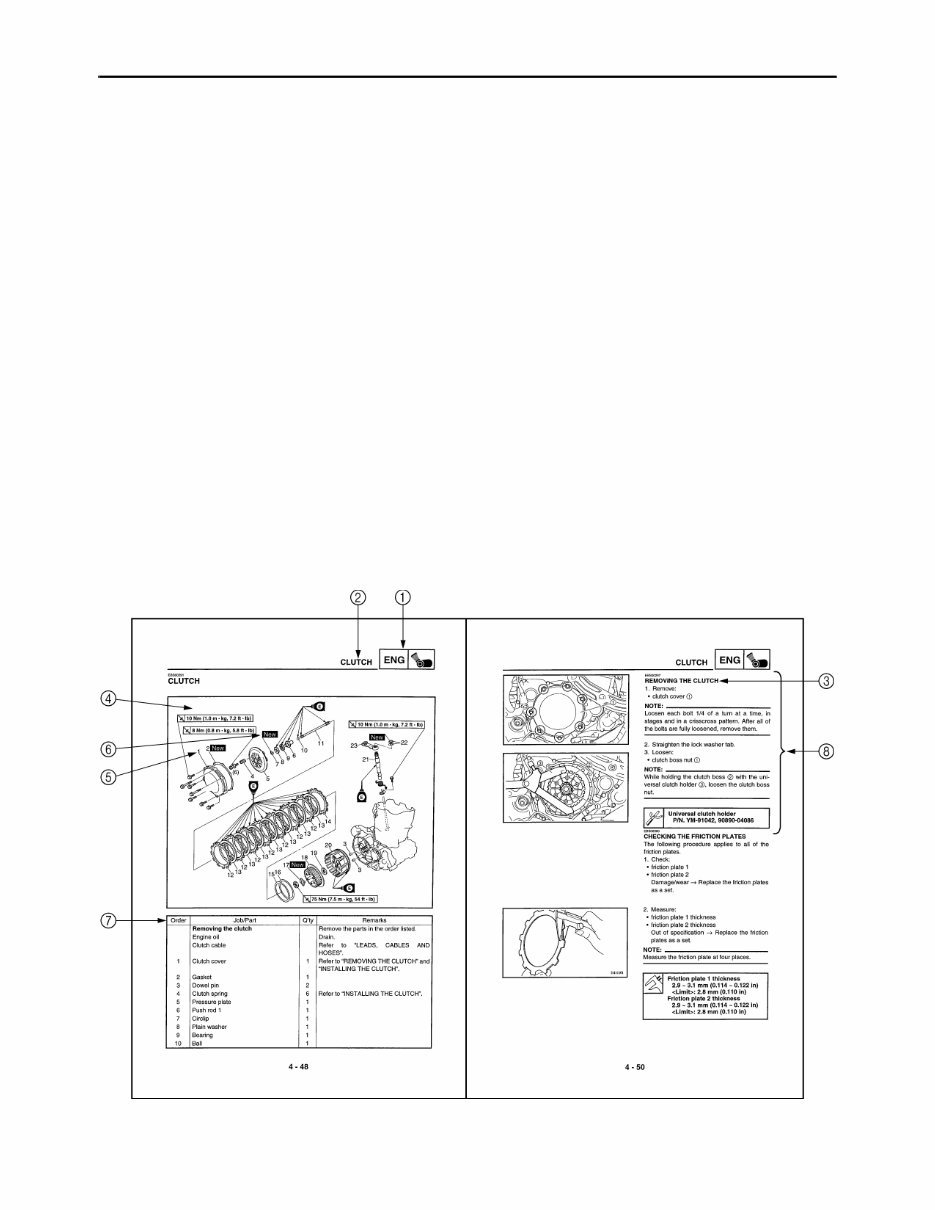
EBS00004 HOW TO USE THIS MANUAL MANUAL ORGANIZATION This manual consists of chapters for the main categories of subjects. (See “symbols”) 1st title 1: This is the title of the chapter with its symbol in the upper right corner of each page. 2nd title 2: This title indicates the section of the chapter and only appears on the first page of each section. It is located in the upper left corner of the page. 3rd title 3: This title indicates a sub-section that is followed by step-by-step procedures accompa- nied by corresponding illustrations. EXPLODED DIAGRAMS To help identify parts and clarify procedure steps, there are exploded diagrams at the start of each removal and disassembly section. 1. An easy-to-see exploded diagram 4 is provided for removal and disassembly jobs. 2. Numbers 5 are given in the order of the jobs in the exploded diagram. A number that is enclosed by a circle indicates a disassembly step. 3. An explanation of jobs and notes is presented in an easy-to-read way by the use of symbol marks 6. The meanings of the symbol marks are given on the next page. 4. A job instruction chart 7 accompanies the exploded diagram, providing the order of jobs, names of parts, notes in jobs, etc. 5. For jobs requiring more information, the step-by-step format supplements 8 are given in addition to the exploded diagram and the job instruction chart.
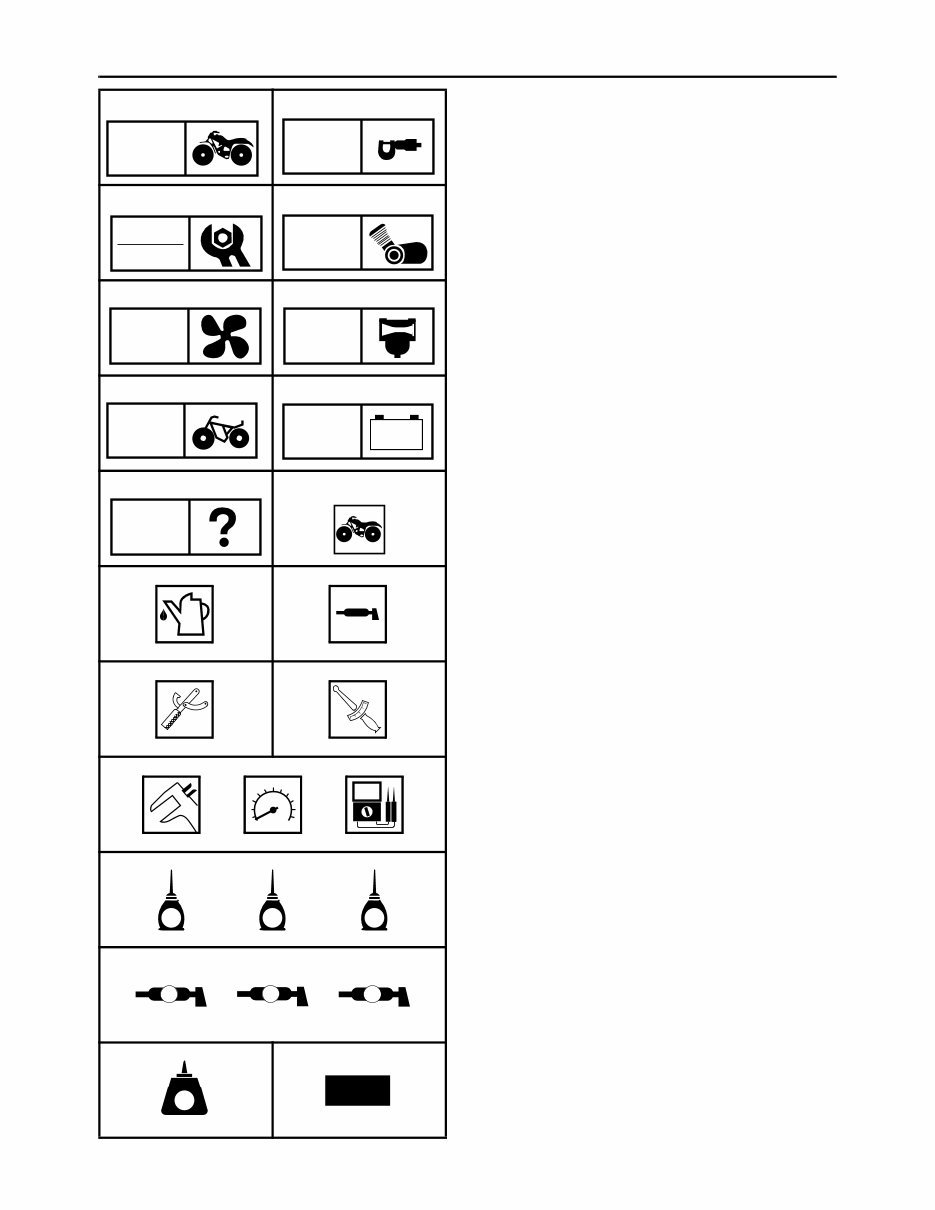
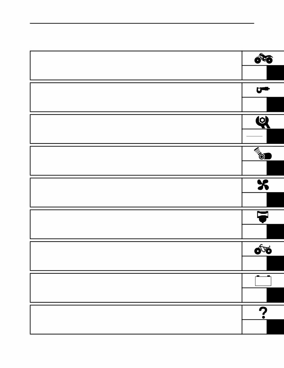
EBS00006 SYMBOLS The following symbols are not relevant to every machine. Symbols 1 to 9 indicate the subject of each chapter. 1 General information 2 Specifications 3 Periodic checks and adjustments 4 Engine 5 Cooling system 6 Carburetor 7 Chassis 8 Electrical 9 Troubleshooting Symbols 0 to G indicate the following 0 Serviceable with engine mounted A Filling fluid B Lubricant C Special tool D Torque E Wear limit, clearance F Engine speed G Electrical data (Ω, V, A) Symbols H to N in the exploded diagrams indicate the types of lubricants and lubrication points. H Apply engine oil I Apply gear oil J Apply molybdenum disulfide oil K Apply wheel bearing grease L Apply lithium-soap-based grease M Apply molybdenum disulfide grease Symbols N to O in the exploded diagrams indicate where to apply a locking agent N and when to install a new part O. N Apply the locking agent (LOCTITE ® ) O Replace 1 2 3 4 5 6 7 8 9 0 A B C D E F G H I J K L M N O GEN INFO SPEC CHK ADJ ENG COOL CARB CHAS – + ELEC TRBL SHTG T R . . E G M B LS M LT New
EBS00008 TABLE OF CONTENTS GENERAL INFORMATION GEN INFO 1 SPECIFICATIONS SPEC 2 PERIODIC CHECKS AND ADJUSTMENTS CHK ADJ 3 ENGINE ENG 4 COOLING SYSTEM COOL 5 CARBURETOR CARB 6 CHASSIS CHAS 7 ELECTRICAL ELEC 8 TROUBLESHOOTING TRBL SHTG 9 – +
CHAPTER 1 GENERAL INFORMATION MACHINE IDENTIFICATION........................................................................... 1-1 VEHICLE IDENTIFICATION NUMBER ..................................................... 1-1 MODEL LABEL.......................................................................................... 1-1 IMPORTANT INFORMATION ......................................................................... 1-2 PREPARATION FOR REMOVAL AND DISASSEMBLY........................... 1-2 REPLACEMENT PARTS........................................................................... 1-2 GASKETS, OIL SEALS AND O-RINGS .................................................... 1-2 LOCK WASHERS/PLATES AND COTTER PINS ..................................... 1-3 BEARINGS AND OIL SEALS .................................................................... 1-3 CIRCLIPS .................................................................................................. 1-3 CHECKING THE CONNECTIONS ............................................................ 1-4 SPECIAL TOOLS ............................................................................................ 1-5 CHAPTER 2 SPECIFICATIONS GENERAL SPECIFICATIONS ........................................................................ 2-1 ENGINE SPECIFICATIONS ............................................................................ 2-4 CHASSIS SPECIFICATIONS ........................................................................ 2-12 ELECTRICAL SPECIFICATIONS ................................................................. 2-14 TIGHTENING TORQUES .............................................................................. 2-16 ENGINE TIGHTENING TORQUES ........................................................ 2-16 CHASSIS TIGHTENING TORQUES ...................................................... 2-19 HOW TO USE THE CONVERSION TABLE.................................................. 2-21 GENERAL TIGHTENING TORQUE SPECIFICATIONS ............................... 2-21 LUBRICATION POINTS AND LUBRICANT TYPES .................................... 2-22 ENGINE ................................................................................................... 2-22 COOLANT FLOW DIAGRAMS ..................................................................... 2-24 OIL FLOW DIAGRAMS ................................................................................. 2-26 CABLE ROUTING ......................................................................................... 2-28
A complete collection workshop repair manual for Yamaha YFZ 450 2004-2009 is available. This manual is designed to assist in diagnosing vehicle-related issues and providing recommended repair and maintenance procedures. It is also suitable for mechanics at all skill levels, including beginners, for tasks such as disassembly, part inspection, rebuilding, and component assembly.
The Yamaha YFZ 450 2004-2009 workshop repair manual is intended for any owner of this vehicle and can be utilized by individuals regardless of their profession.
Instant access! No waiting time required. The manual will be delivered immediately via email.
Format: .PDF / .OVA. Compatibility: All operating system versions for devices with a compatible reader.