

1998 Yamaha Wolverine 350 Service Repair Manual 98
What's Included?
Fast Download Speeds
Online & Offline Access
Access PDF Contents & Bookmarks
Full Search Facility
Print one or all pages of your manual
YFM35FXG
Service Manual
YAMAHA
LIT-11616-09·95
'
FOREWORD
This Supplementary Service Manual has been prepa,.red to introduce new service and data for
the YFM35FXH . For complete service information procedures, it is necessary to use this
Supplementary Service Manual together with the following manual.
YFM35FXG SERVICE MANUAL: 4KB-28197-20
YFM35FXH
SUPPLEMENTARY
SERVICE MANUAL
@1995 by Yamaha Motor Co., Ltd.
1st Edition, September 1995
All rights reserved. Any reprinting or
unauthorized use without the written
permission of Yamaha Motor Co., Ltd.
is expressly prohibited.
NOTICE
This manual was written by the Yamaha Motor Company, Ltd. primarily for use b,y Yamaha
dealers and qualified mechanics. It is not possible to put an entire mechanic's education into one
manual, so persons using this book to perform maintenance and repairs on Yamaha machines
should have a basic understanding of the mechanical concepts and procedures inherent in
machine repair technology. Without such knowledge, attempted repairs or service to the
machine may render it unfit to use and/or unsafe.
Yamaha Motor Company, Ltd. is continually striving to improve all models manufactured by
Yamaha. Modifications and significant changes in specifications or procedures will be for-
warded to all Authorized Yamaha dealers and will, where applicable, appear in future editions
of this manual.
PARTICULARLY IMPORTANT INFORMATION
This material is distinguished by the following notation.
A WARNING
NOTE:
The Safety Alert Symbol means ATTENTION! BECOME ALERT! YOUR
SAFETY IS INVOLVED!
Failure to follow WARNING instructions could result in severe injury or
death to the machine operator, a bystander, or a person inspecting or
repairing the machine.
A CAUTION indicates special precautions that must be taken to avoid
damage to the machine.
A NOTE provides key information to make procedures easier or clearer.
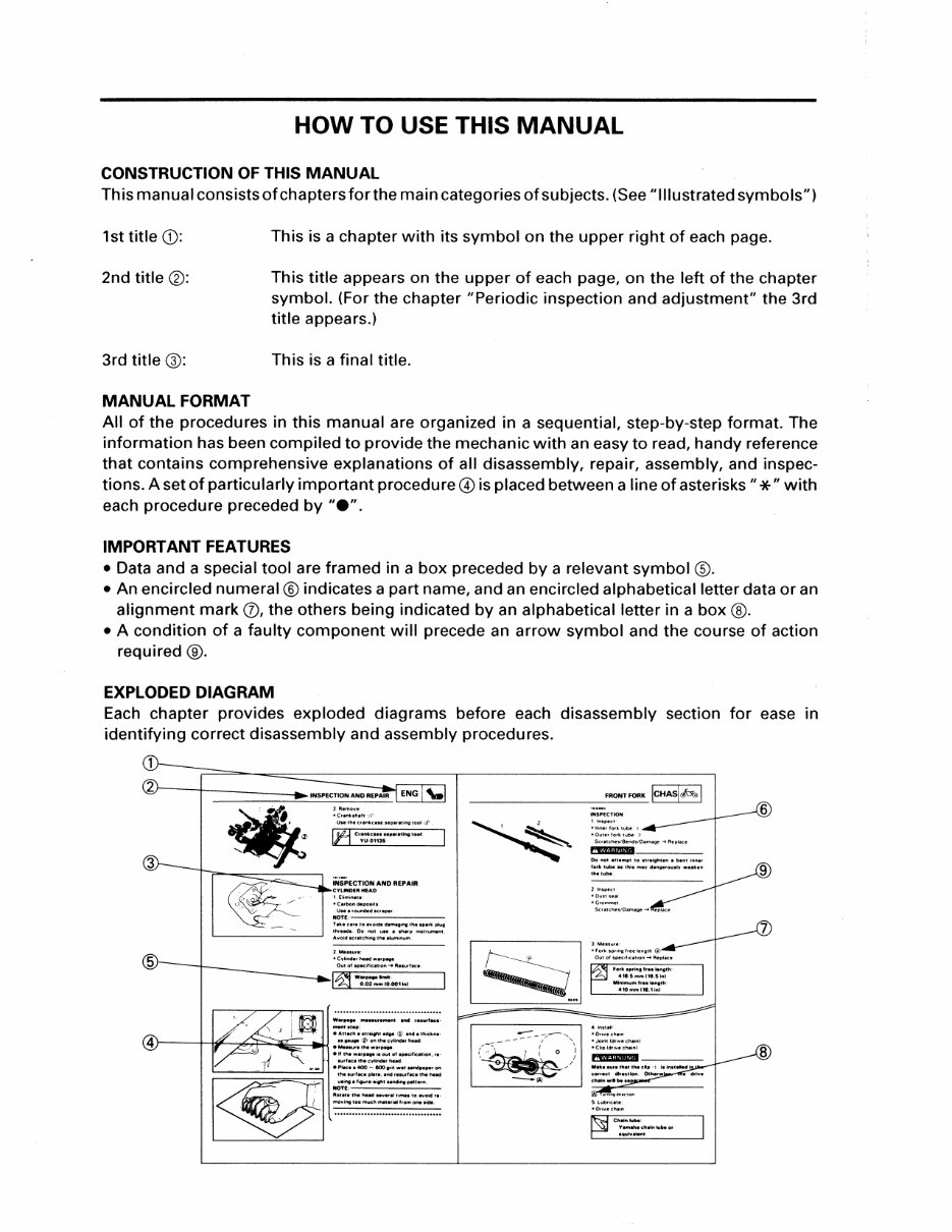
HOW TO USE THIS MANUAL
CONSTRUCTION OF THIS MANUAL
This manual consists of chapters for the main categories of subjects. (See" Illustrated symbols")
1st title CD:
This is a chapter with its symbol on the upper right of each page.
2nd title®:
This title appears on the upper of each page, on the left of the chapter
symbol. (For the chapter "Periodic inspection and adjustment" the 3rd
title appears.)
3rd title@:
This is a final title.
MANUAL FORMAT
All of the procedures in this manual are organized in a sequential, step-by-step format. The
information has been compiled to provide the mechanic with an easy to read, handy reference
that contains comprehensive explanations of all disassembly, repair, assembly, and inspec-
tions. A set of particularly important procedure@ is placed between a line of asterisks"*" with
each procedure preceded by "e".
IMPORTANT FEATURES
• Data and a special tool are framed in a box preceded by a relevant symbol @.
• An encircled numeral® indicates a part name, and an encircled alphabetical letter data or an
alignment mark (j), the others being indicated by an alphabetical letter in a box@.
• A condition of a faulty component will precede an arrow symbol and the course of action
required@.
EXPLODED DIAGRAM
Each chapter provides exploded diagrams before each disassembly section for ease in
identifying correct disassembly and assembly procedures.
UsethltCrlnkc .. eHplrltingtool Cl'.
lt=i Cr~~~;;-..-a~l,..tool:
Ueeeroundlld*<:rlper.
NOTE,----'---'-------
hkiCai'IIO..,Ooded .......... lhelpllfkplug
'-------------' :::-~,: .. :,:~:.-::. onstr..,.nl .
...... -· ..... ··-·-- _...,.,,
•Auachestreightedgol CD endethiciiM-
}---+t.~-z?J:~~rl~ .::.=.!:,:::.lind•rhud.
elfthltwllfO ... iloutofepecifiellliol'l,re·
surf~~eetheey~nderheH.
'---- ...... !._ __ _____:•:=..~·• ePIM:ee400- IOOtrit •" Nl'ldlNI,.. on
~~~~
FRONT •""• icHASI A I
-----------------
1 lnSPKI
CD ®
~~~~~~~
lsPEcl u--1
@ @
l•:g!l-.1 IENGI\.1
® ®
lcooLI~I lcARBI Iii I
(j) @
lcHAsl6lOI IELEcjol
®
@)
[1)]
IJ~~~? I
®
B
@
~
@
~
®
~
®
[8]
®
~
@ @) @
l l l
m ~ ~
®
@ @
~ ....... .......
@
®
A
~
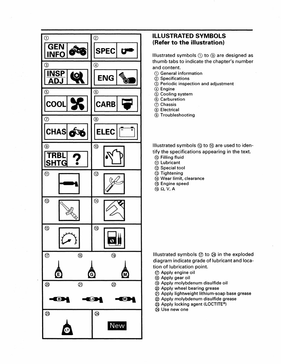
ILLUSTRATED SYMBOLS
(Refer to the illustration)
Illustrated symbols CD to ® are designed as
thumb tabs to indicate the chapter's number
and content.
CD General information
®Specifications
@ Periodic inspection and adjustment
@Engine
®Cooling system
® Carburetion
(J) Chassis
® Electrical
® Troubleshooting
Illustrated symbols@) to@ are used to iden-
tify the specifications appearing in the text.
@) Filling fluid
®Lubricant
@ Special tool
@ Tightening
@ Wear limit, clearance
® Engine speed
@Q,V,A
Illustrated symbols @ to ® in the exploded
diagram indicate grade of lubricant and loca-
tion of lubrication point.
@ Apply engine oil
@ Apply gear oil
@)Apply molybdenum disulfide oil
®Apply wheel bearing grease
@ Apply lightweight lithium-soap base grease
@ Apply molybdenum disulfide grease
@Apply locking agent (LOCTITE®)
®Use new one
CONTENTS
GENERAL INFORMATION .......................................................................................... 1
MACHINE IDENTIFICAtiON ................................................................................. 1
VEHICLE IDENTIFICATION NUMBER ............................................................ 1
FRAME SERIAL NUMBER .............................................................................. 1
ENGINE SERIAL NUMBER ............................................................................. 1
SPECIFICATIONS ........................................................................................................ 2
GENERAL SPECIFICATIONS ................................................................................. 2
MAINTENANCE SPECIFICATIONS ....................................................................... 2
ENGINE ............................................................................................................. 2
ELECTRICAL .................................................................................................... 3
TIGHTENING TORQUE ................................................................................... 4
CABLE ROUTING ................................................................................................... 6
CARBURETION .. .. .. .. ... .... .. .. ....... ..... .... . .. ......... ...... ..... .. .. ..... .... ... .. ............. ... .. .. .. ... .. .. 11
CARBURETOR ..................................................................................................... 11
ELECTRICAL ............................................................................................................... 12
IGNITION SYSTEM .............................................................................................. 12
CIRCUIT DIAGRAM ....................................................................................... 12
ENGINE REVOLUTION LIMITER SYSTEM .................................................. 13
YFM35FXH WIRING DIAGRAM
MACHINE IDENTIFICATION I ~~~ I o'el
GENERAL INFORMATION
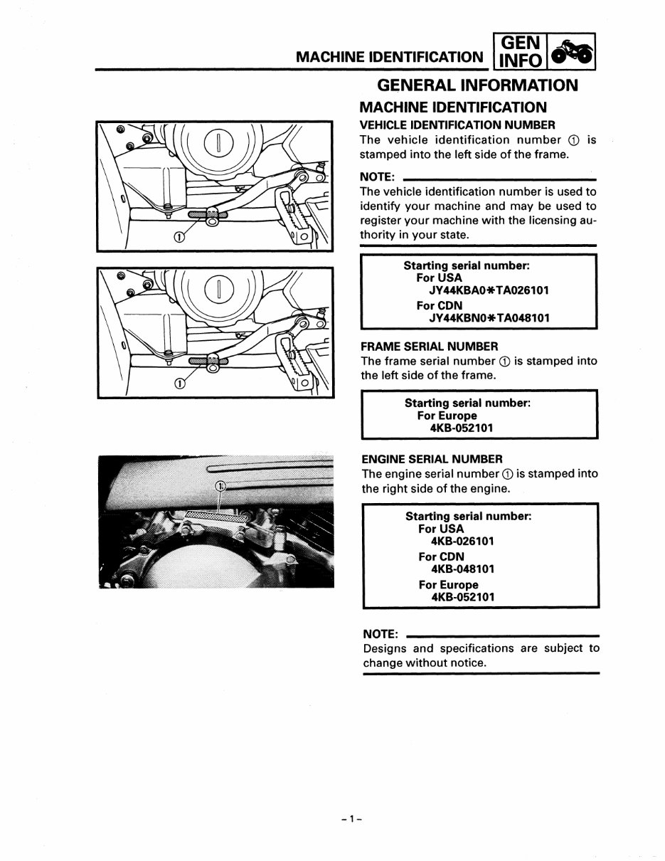
MACHINE IDENTIFICATION
VEHICLE IDENTIFICATION NUMBER
The vehicle identification number <D is
stamped into the left side of the frame.
NOTE:
The vehicle identification number is used to
identify your machine and may be used to
register your machine with the licensing au-
thority in your state.
Starting serial number:
For USA
JY 44KBAO* TA026101
ForCDN
JV 44KBNO* TA048101
FRAME SERIAL NUMBER
The frame serial number <D is stamped into
the left side of the frame.
Starting serial number:
For Europe
4KB-052101
ENGINE SERIAL NUMBER
The engine serial number <Dis stamped into
the right side of the engine.
-1-
NOTE:
Starting serial number:
For USA
4KB-026101
ForCDN
4KB-048101
For Europe
4KB-052101
Designs and specifications are subject to
change without notice.
GENERAL SPECIFICATIONS/ I I I
MAINTENANCE SPECIFICATIONS SPEC a--
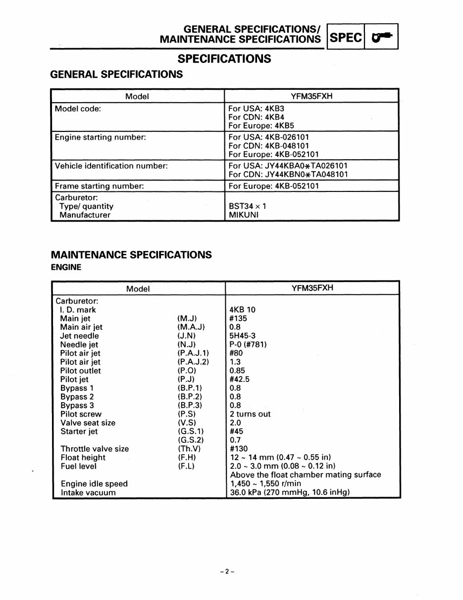
SPECIFICATIONS
GENERAL SPECIFICATIONS
Model
Model code:
Engine starting number:
Vehicle identification number:
Frame starting number:
Carburetor:
Type/ quantity
Manufacturer
MAINTENANCE SPECIFICATIONS
ENGINE
Model
Carburetor:
I. D. mark
Main jet (M.J)
Main air jet (M.A.J)
Jet needle (J.N)
Needle jet (N.J)
Pilot air jet (P.A.J.1)
Pilot air jet (P.A.J.2)
Pilot outlet (P.O)
Pilot jet (P.J)
Bypass 1 (B.P.1)
Bypass 2 (B.P.2)
Bypass 3 (B.P.3)
Pilot screw (P.S)
Valve seat size (V.S)
Starter jet (G.S.1)
(G.S.2)
Throttle valve size (Th.V)
Float height (F.H)
Fuel level (F.L)
Engine idle speed
Intake vacuum
YFM35FXH
For USA: 4KB3
For CON: 4KB4
For Europe: 4KB5
For USA: 4KB-026101
For CON: 4KB-048101
For Europe: 4KB-052101
For USA: JY44KBAO*TA026101
For CON: JY44KBNO*TA048101
For Europe: 4KB-052101
BST34 X 1
MIKUNI
YFM35FXH
4KB 10
#135
0.8
5H45-3
P-0 (#781)
#80
1.3
0.85
#42.5
0.8
0.8
0.8
2 turns out
2.0
#45
0.7
#130
12- 14 mm (0.47- 0.55 in)
2.0- 3.0 mm (0.08- 0.12 in)
Above the float chamber mating surface
1,450- 1,550 r/min
36.0 kPa (270 mmHg, 10.6 inHg)
-2-
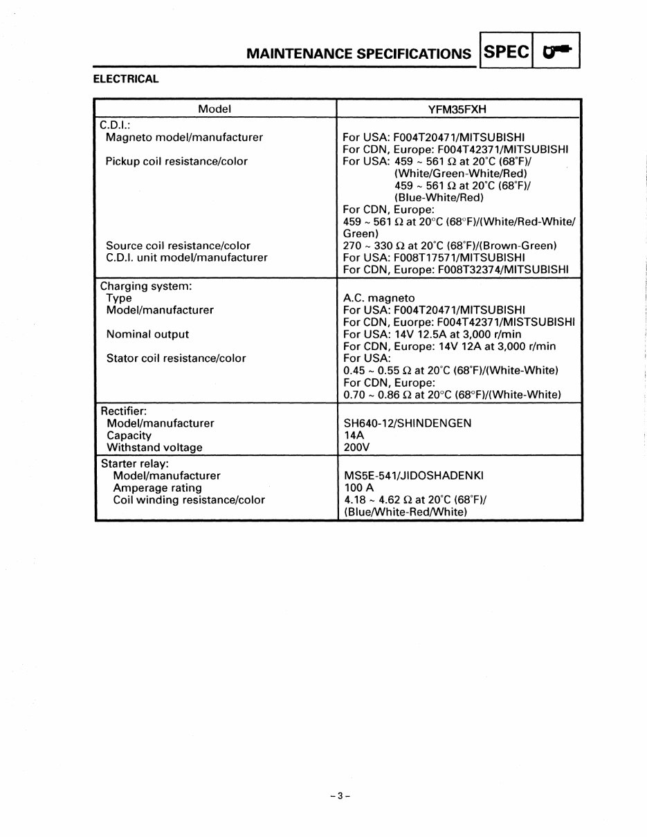
MAINTENANCE SPECIFICATIONS lsPECI o-1
ELECTRICAL
Model
C.O.I.:
Magneto model/manufacturer
Pickup coil resistance/color
Source coil resistance/color
C.O.I. unit model/manufacturer
Charging system:
Type
Model/manufacturer
Nominal output
Stator coil resistance/color
Rectifier:
Model/manufacturer
Capacity
Withstand voltage
Starter relay:
Model/manufacturer
Amperage rating
Coil winding resistance/color
YFM35FXH
For USA: F004T20471/MITSUBISHI
For CON, Europe: F004T42371/MITSUBISHI
For USA: 459 - 561 nat 2o·c (68.F)/
(White/Green-White/Red)
459 - 561 nat 2o·c (68.F)/
(Blue-White/Red)
For CON, Europe:
459 - 561 nat 20°C (68°F)/(White/Red-White/
Green)
270- 330 0 at 2o·c (68.F)/(Brown-Green)
For USA: F008T17571/MITSUBISHI
For CON, Europe: F008T3237 4/MITSUBISHI
A.C. magneto
For USA: F004T20471/MITSUBISHI
For CON, Euorpe: F004T42371/MISTSUBISHI
For USA: 14V 12.5A at 3,000 r/min
For CON, Europe: 14V 12A at 3,000 r/min
For USA:
0.45 - 0.55 nat 2o·c (68.F)/(White-White)
For CON, Europe:
0.70 - 0.86 Qat 20°C (68°F)/(White-White)
SH640-12/SHINOENGEN
14A
200V
MS5E-541/JIOOSHAOENKI
100A
4.18- 4.62 nat 2o·c (68.F)/
(Blue/White-Red/White)
-3-
You're Reading a Preview
What's Included?
Fast Download Speeds
Online & Offline Access
Access PDF Contents & Bookmarks
Full Search Facility
Print one or all pages of your manual
$28.99
$37.99
Viewed 70 Times Today


Secure transaction
What's Included?
Fast Download Speeds
Online & Offline Access
Access PDF Contents & Bookmarks
Full Search Facility
Print one or all pages of your manual
$28.99
$37.99
This manual contains essential information for maintaining and repairing your Yamaha Wolverine 95-05. It is the same manual used by your local dealer and covers over 320 pages of valuable content. Whether you are a professional mechanic or a DIY enthusiast, this manual is a valuable resource for:
- General Information
- Maintenance
- Engine Removal and Installation
- Engine Fuel System
- Engine Lubrication and Cooling
- Engine Combustion System
- Transmission System
- Front Wheel and Steering System
- Rear Wheel System
- Fenders and Exhaust Pipe
- Electrical System
- Troubleshooting


