

1992-2000 Yamaha Timberwolf 250 YFB250 Service & Repair Manual
What's Included?
Fast Download Speeds
Online & Offline Access
Access PDF Contents & Bookmarks
Full Search Facility
Print one or all pages of your manual
.YAMAHA
YFB250
YAMAHA
,.
LlT-11616-08-17

YF8250(D) '92
SERVICE MANUAL
© 1991 by Yamaha Motor Co., Ltd.
1st Edition, September 1991
All rights reserved. Any reprinting or
unauthorized use without the written
permission of Yamaha Motor Co., Ltd.
is expressly prohibited.
NOTICE
This manual was written by the Yamaha Motor Company, Ltd. primarily for use by Yamaha dealers and
qualified mechanics. It is not possible to put an entire mechanic's education into one manual, so persons
using this book to perform maintenance and repairs on Yamaha machines should have a basic
understanding of the machanical concepts and procedures inherent in machine repair technology.
Without such knowledge, attempted repairs or service to the machine may render it unfit to use and/or
unsafe.
Yamaha Motor Company, Ltd. is continually striving to improve all models manufactured by Yamaha.
Modifications and significant changes in specifications or procedures will be forwarded to all Authorized
Yamaha dealers and will, where applicable, appear in future editions of this manual.
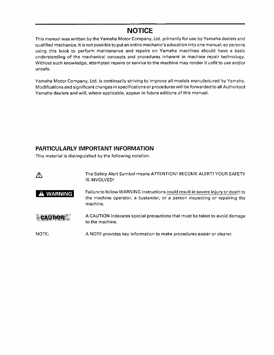
PARTICULARLY IMPORTANT INFORMATION
This material is distinguished by the following notation.
A WARNING
NOTE:
The Safety Alert Symbol means ATTENTION! BECOME ALERT! YOUR SAFETY
IS INVOLVED!
Failure to follow WARNING instructions could result in severe injury or death to
the machine operator, a bystander, or a person inspecting or repairing the
machine.
A CAUTION indecates special precautions that must be taken to avoid damage
to the machine.
A NOTE provides key information to make procedures easier or clearer.
HOW TO USE THIS MANUAL
CONSTRUCTION OF THIS MANUAL
Tris manual consists of chapters for the main categories of subjects. (See "Illustrated symbols")
This is a chapter with its symbol on the upper right of each page. 1 st title CD :
2nd title ® : This title appears on the upper of each page on the left of the chapter
symbol. (For the chapter "Periodic inspection and adjustment" the 3rd
title appears.)
3rd title ® : This is a final title.
MANUAL FORMAT
All of the procedures in this manual are organized in a sequential, step-by-step format. The infor-
mation has been compiled to provide the mechanic with an easy to read, handy reference that
contains comprehensive explanations of all disassembly, repair, assembly, and inspections.
A set of particularly important procedure @ is placed between a line of asterisks" *" with each
procedure preceded by " • ".
IMPORTANT FEATURES
• Data and a special tool are framed in a box preceded by a relevant symbol @ .
• An encircled numeral ® indicates a part name, and an encircled alphabetical letter data or an
alignl11ent mark (j) , the others being indicated by an alphabetical letter in a box ® .
• A condition of a faulty component will precede an arrow symbol and the course of action re-
ql,Jired the l>ymbol ®.
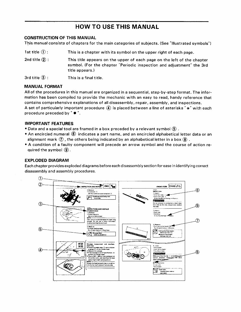
EXPLODED DIAGRAM
Each chqpter provides exploded diagrams before each disassembly section for ease in identifying correct
disassembly and assembly procedures.
3
2.Rllmov,,"
·c ....... '''.11 ill
Use,hec.llnkcl,"nplrll"nlllOOI (J)
1i1 C'~:~~~;:.'."111tf tool:
n--::=:::;;::;;;:==, IN'SPECTION AND REPAIR
CYLIHI)ER HEAD
1, E~ ... " •• te
·C.tbo"dllPOI,ts
U ••• ,oun.s.d.o::',~,
H07l:, ..... :--- ...... :---.---
TlkeCII,"toIlVo.dlldlmagongthelptrkp1ue
'----________ --' ~~::::C'~I:h~:;t~::lu .... ~h:.: ,nWUIO\eIl'
Warpfl ...... H"'._t.net , ...... ,.e •.
-"".t.,:
•• U.ch." .... ' .. <D...ct.thod' ... ·
)----H~--A~~~~ .:':'=t~.:;~:;:.~nHtlwld
."th.w.'~i.OulOI."."ifiulion.'.·
.",'.~. t"- "ybtld., h.ad
• PI.~ •• 400 - eoo 'fit w., lind""", on
~
:::'::~:,:~:;;':::':':::::.:~''''''
J :::; lh. Iwlld ....... " I"'", to .... oid •• •
I moving 100 m""h mat.,"1 from _ 'idil.
., "" ... """"""""'''"'''' .. ,,
FRONT FOR. ICHASlbel
-----------------
llnsPllel
"InMtforktube 1
'O"III,IO'k lube 2
Sc .. lches/S."'dsIOamage .... Replace
riDliBIID ___ _
00 nOI """mpll0 1t,"igM." II b.", in".,
lo.k IlIbe., 11111 mllvdlln, •• O"I'y ••••• n
Ihllube
21nspeCI
'G'ommel
Sc •• tehes/Ollm"g,,"" eplace
• JOInt Id"ve ~h"nl
·Cllpld"vechllnl
6
9
7
8
CD ®
I~EF~I"'I
ISPECI )Ofl
®
@
Ih~rlfil
1 ENG 1'-1
® ®
ICARBI'I
IOR1VI.p1
(j) @
ICHASlhl I HECI iii I
®
@
~ I~~¥~? 1
(jJ)
~
@
lEJ
@
~
®
~
@
§
@
[ml
@
1
@ @
1 1
OJ
-
a m
® ®
@
~ ~~
@
,
A
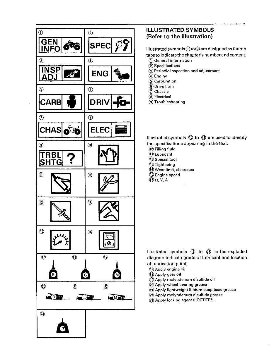
ILLUSTRATED SYMBOLS
(Refer to the illustration)
Illustrated symbolsCDto@aredesignedasthumb
tabs to indicate the chapter's number and content.
CD General informati6n
® Specifications
® Periodic inspection and adjustment
@Engine
® Carburetion
® Drive train
(j) Chassis
@ Electrical
® Troubleshooting
Illustrated symbols @ to @ are used to identify
the specifications appearing in the text.
@ Filling fluid
(jJ) Lubricant
@ Special tool
@Tightening
® Wear limit, clearance
@ Engine speed
@n,V,A
Illustrated symbols @ to @ in the exploded
diagram indicate grade of lubricant and location
of lubrication point.
@ Apply engine oil
@ Apply gear oil
@ Apply molybdenum disulfide 011
® Apply wheel bearing grease
® Apply lightweight lithium-soap base grease
@ Apply molybdenum disulfide grease
@ Apply locking agent (LOCrITE~)
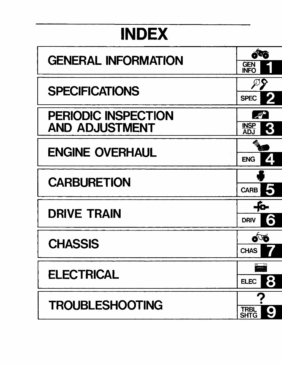
INDEX
GENERAL INFORMATION
SPECIFICATIONS
PERIODIC INSPECTION
AND ADJUSTMENT
ENGINE OVERHAUL
CARBURETION
DRIVE TRAIN
CHASSIS
ELECTRICAL
TROUBLESHOOTING
0'1
GEN
INFO
SPEC
R
INSP
ADJ
...
ENG
•
CHAS
ELEC
?
•
to---
TRBL
SHTG
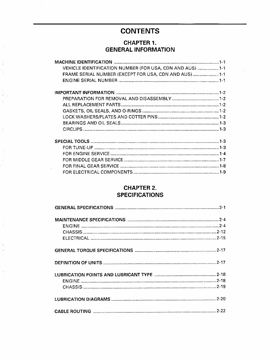
CONTENTS
CHAPTER 1.
GENERAL INFORMATION
MACHINE IDENTIFICATION ..................................................................................... 1-1
VEHICLE IDENTIFICATION NUMBER (FOR USA, CDN AND AUS) ................. 1-1
FRAME SERIAL NUMBER (EXCEPT FOR USA, CDN AND AUS) ..................... 1-1
ENGINE SERIAL NUMBER ................................................................................. 1-1
IMPORTANT INFORMATION ................................................................................... 1-2
PREPARATION FOR REMOVAL AND DISASSEMBLY ...................................... 1-2
ALL REPLACEMENT PARTS ............................................................................... 1-2
GASKETS, OIL SEALS, AND O-RINGS .............................................................. 1-2
LOCK WASHERS/PLATES AND COTTER PINS ................................................. 1-2
BEARINGS AND OIL SEALS ............................................................................... 1-3
CIRCLIPS ............................................................................................................... 1-3
SPECIAL TOOLS ........................................................................................................ 1-3
FOR TUNE-UP ..................................................................................................... 1-3
FOR ENGINE SERVICE ........................................................................................ 1-4
FOR MIDDLE GEAR SERVICE ............................................................................. 1-7
FOR FINAL GEAR SERVICE ................................................................................ 1-8
FOR ELECTRICAL COMPONENTS ..................................................................... 1-9
CHAPTER 2.
SPECIFICATIONS
GENERAL SPECIFICATIONS .................................................................................... 2-1
MAINTENANCE SPECIFICATIONS .......................................................................... 2-4
ENGINE ................................................................................................................ 2-4
CHASSIS ............................................................................................................ 2-12
ELECTRICAL ...................................................................................................... 2-15
GENERAL TORQUE SPECIFICATIONS .................................................................. 2-17
DEFINITION OF UNITS ............................................................................................ 2-17
LUBRICATION POINTS AND LUBRICANT TYPE .................................................. 2-18
ENGINE .............................................................................................................. 2-18
CHASSIS ............................................................................................................ 2-19
LUBRICATION DIAGRAMS ..................................................................................... 2-20
CABLE ROUTING .................................................................................................... 2-22
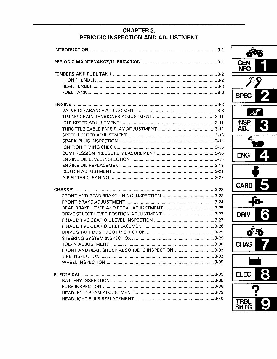
CHAPTER 3.
PERIODIC INSPECTION AND ADJUSTMENT
INTRODUCTION ........................................................................................................ 3-1
PERIODIC MAINTENANCE/LUBRICATION ............................................................. 3-1
FENDERS AND FUEL TANK ..................................................................................... 3-2
FRONT FENDER .................................................................................................. 3-2
REAR FENDER ..................................................................................................... 3-3
FUEL TANK .......................................................................................................... 3-6
ENGINE ...................................................................................................................... 3-8
VALVE CLEARANCE ADJUSTMENT ................................................................. 3-8
TIMING CHAIN TENSIONER ADJUSTMENT .................................................. 3-11
IDLE SPEED ADJUSTMENT ............................................................................. 3-11
THROTTLE CABLE FREE PLAY ADJUSTMENT .............................................. 3-12
SPEED LIMITER ADJUSTMENT ....................................................................... 3-13
SPARK PLUG INSPECTION .............................................................................. 3-14
IGNITION TIMING CHECK ................................................................................ 3-15
COMPRESSION PRESSURE MEASUREMENT ............................................... 3-16
ENGINE OIL LEVEL INSPECTION .................................................................... 3-18
ENGINE OIL REPLACEMENT ............................................................................ 3-19
CLUTCH ADJUSTMENT ................................................................................... 3-21
AIR FILTER CLEANING ..................................................................................... 3-22
CHASSIS .................................................................................................................. 3-23
FRONT AND REAR BRAKE LINING INSPECTION ........................................... 3-23
FRONT BRAKE ADJUSTMENT ........................................................................ 3-24
REAR BRAKE LEVER AND PEDAL ADJUSTMENT ......................................... 3-25
DRIVE SELECT LEVER POSITION ADJUSTMENT .......................................... 3-27
FINAL DRIVE GEAR OIL LEVEL INSPECTION ................................................. 3-27
FINAL DRIVE GEAR OIL REPLACEMENT ........................................................ 3-28
DRIVE SHAFT DUST BOOT INSPECTION ....................................................... 3-29
STEERING SYSTEM INSPECTION ................................................................... 3-29
TOE-IN ADJUSTMENT ..................................................................................... 3-30
FRONT AND REAR SHOCK ABSORBERS INSPECTION ................................ 3-32
TIRE INSPECTION ............................................................................................. 3-33
WHEEL INSPECTION ........................................................................................ 3-35
ELECTRICAL ............................................................................................................ 3-35
BATTERY INSPECTION ..................................................................................... 3-35
FUSE INSPECTION ........................................................................................... 3-38
HEADLIGHT BEAM ADJUSTMENT ................................................................. 3-39
HEADLIGHT BULB REPLACEMENT ................................................................. 3-40
.1(0.
t-----
GEN
INFO
SPEC
fi
t-----
INSP
ADJ
~- t---- ..... ;
ENG
J-----'
CARB
-ra-
t-----
DRIV
CHAS
ELEC
?
1---- .....
TRBL
SHTG
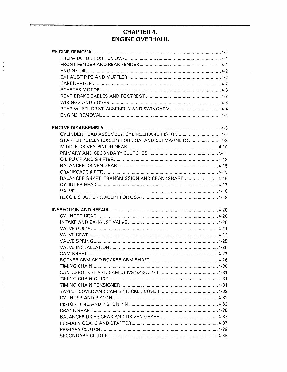
CHAPTER 4.
ENGINE OVERHAUL
ENGINE REMOVAL ................................................................................................... 4-1
PREPARATION FOR REMOVAL ......................................................................... 4-1
FRONT FENDER AND REAR FENDER ................................................................ 4-1
ENGINE OIL ......................................................................................................... 4-2
EXHAUST PIPE AND MUFFLER ......................................................................... 4-2
CARBURETOR ..................................................................................................... 4-2
STARTER MOTOR ............................................................................................... 4-3
REAR BRAKE CABLES AND FOOTREST ........................................................... 4-3
WIRINGS AND HOSES ....................................................................................... 4-3
REAR WHEEL DRIVE ASSEMBLY AND SWINGARM ....................................... 4-4
ENGINE REMOVAL ............................................................................................. 4-4
ENGINE DISASSEMBLY ........................................................................................... 4-5
CYLINDER HEAD ASSEMBLY, CYLINDER AND PISTON ................................. 4-5
STARTER PULLEY (EXCEPT FOR USA) AND CDI MAGNETO ......................... 4-8
MIDDLE DRIVEN PINION GEAR ....................................................................... 4-10
PRIMARY AND SECONDARY CLUTCHES ....................................................... 4-11
OIL PUMP AND SHIFTER .................................................................................. 4-13
BALANCER DRIVEN GEAR ............................................................................... 4-15
CRANKCASE (LEFT) .......................................................................................... 4-15
BALANCER SHAFT, TRANSMISSION AND CRANKSHAFT ........................... 4-16
CYLINDER HEAD ............................................................................................... 4-17
VALVE ................................................................................................................ 4-18
RECOIL STARTER (EXCEPT FOR USA) ........................................................... 4-19
INSPECTION AND REPAIR ..................................................................................... 4-20
CYLINDER HEAD ............................................................................................... 4-20
INTAKE AND EXHAUST VALVE ....................................................................... 4-20
VALVE GUIDE .................................................................................................... 4-21
VALVE SEAT ...................................................................................................... 4-22
VALVE SPRING .................................................................................................. 4-25
VALVE INSTALLATION ..................................................................................... 4-26
CAM SHAFT ....................................................................................................... 4-27
ROCKER ARM AND ROCKER ARM SHAFT ..................................................... 4-28
TIMING CHAIN .................................................................................................. 4-30
CAM SPROCKET AND CAM DRIVE SPROCKET ............................................. 4-31
TIMING CHAIN GUIDE ...................................................................................... 4-31
TIMING CHAIN TENSIONER ............................................................................ 4-31
TAPPET COVER AND CAM SPROCKET COVER ............................................. 4-32
CYLINDER AND PiSTON ................................................................................... 4-32
PISTON RING AND PISTON PIN ...................................................................... 4-33
CRAN K SHAFT .................................................................................................. 4-36
BALANCER DRIVE GEAR AND DRIVEN GEARS ............................................. 4-37
PRIMARY GEARS AND STARTER .................................................................... 4-37
PRIMARY CLUTCH ............................................................................................ 4-38
SECONDARY CLUTCH ...................................................................................... 4-38
You're Reading a Preview
What's Included?
Fast Download Speeds
Online & Offline Access
Access PDF Contents & Bookmarks
Full Search Facility
Print one or all pages of your manual
$31.99
Viewed 39 Times Today


Secure transaction
What's Included?
Fast Download Speeds
Online & Offline Access
Access PDF Contents & Bookmarks
Full Search Facility
Print one or all pages of your manual
$31.99
- This digital manual is an essential resource for anyone working on the 1992-2000 Yamaha Timberwolf 250 ATV, covering both 2wd and 4x4 models.
- With 688 pages, it provides comprehensive guidance for complete tear down and rebuild, including detailed pictures and part diagrams, torque specs, maintenance procedures, and troubleshooting techniques.
- It features clickable chapters and is searchable, allowing for easy navigation and quick access to the required information.
- There are no restrictions on printing or saving/burning to disc, providing convenient access to the manual.
- Whether you are a professional mechanic or a DIY enthusiast, this manual is an invaluable tool for maintaining and repairing the Yamaha Timberwolf 250 ATV.


