EBS00002 NOTICE This manual was produced by the Yamaha Motor Company primarily for use by Yamaha dealers and their qualified mechanics. It is not possible to include all the knowledge of a mechanic in one manual, so it is assumed that anyone who uses this book to perform maintenance and repairs on Yamaha machine has a basic understanding of the mechanical ideas and the procedures of machine repair. Repairs attempted by anyone without this knowledge are likely to render the machine unsafe and unfit for use. Yamaha Motor Company, Ltd. is continually striving to improve all its models. Modifications and sig- nificant changes in specifications or procedures will be forwarded to all authorized Yamaha dealers and will appear in future editions of this manual where applicable. NOTE: _ Designs and specifications are subject to change without notice. EBS00003 IMPORTANT INFORMATION Particularly important information is distinguished in this manual by the following notations. The Safety Alert Symbol means ATTENTION! BECOME ALERT! YOUR SAFETY IS INVOLVED! Failure to follow WARNING instructions could result in severe injury or death to the machine operator, a bystander or a person checking or repairing the machine. A CAUTION indicates special precautions that must be taken to avoid dam- age to the machine. A NOTE provides key information to make procedures easier or clearer. WARNING CAUTION: NOTE:
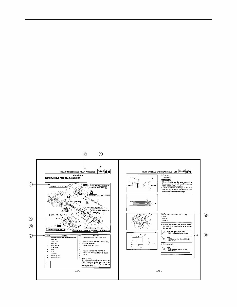
EBS00004 HOW TO USE THIS MANUAL MANUAL ORGANIZATION This manual consists of chapters for the main categories of subjects. (See “symbols”) 1st title 1: This is the title of the chapter with its symbol in the upper right corner of each page. 2nd title 2: This title indicates the section of the chapter and only appears on the first page of each section. It is located in the upper left corner of the page. 3rd title 3: This title indicates a sub-section that is followed by step-by-step procedures accompa- nied by corresponding illustrations. EXPLODED DIAGRAMS To help identify parts and clarify procedure steps, there are exploded diagrams at the start of each removal and disassembly section. 1. An easy-to-see exploded diagram 4 is provided for removal and disassembly jobs. 2. Numbers 5 are given in the order of the jobs in the exploded diagram. A number that is enclosed by a circle indicates a disassembly step. 3. An explanation of jobs and notes is presented in an easy-to-read way by the use of symbol marks 6. The meanings of the symbol marks are given on the next page. 4. A job instruction chart 7 accompanies the exploded diagram, providing the order of jobs, names of parts, notes in jobs, etc. 5. For jobs requiring more information, the step-by-step format supplements 8 are given in addition to the exploded diagram and the job instruction chart.
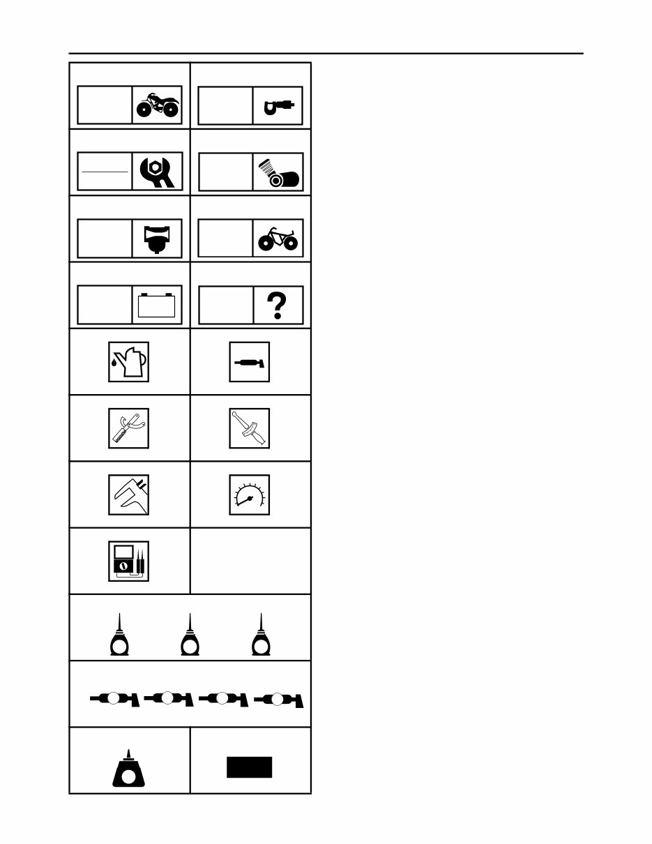
EB003000 ILLUSTRATED SYMBOLS Illustrated symbols 1 to 8 are printed on the top right of each page and indicate the subject of each chapter. 1 General information 2 Specifications 3 Periodic checks and adjustments 4 Engine 5 Carburetion 6 Chassis 7 Electrical 8 Troubleshooting Illustrated symbols 9 to E are used to identify the specifications appearing in the text. 9 Filling fluid 0 Lubricant A Special tool B Torque C Wear limit, clearance D Engine speed E Ω, V, A Illustrated symbols F to L in the exploded diagrams indicate the types of lubricants and lubrication points. F Apply engine oil G Apply gear oil H Apply molybdenum disulfide oil I Apply wheel bearing grease J Apply lightweight lithium soap base grease K Apply molybdenum disulfide grease L Apply silicon grease Illustrated symbols M to N in the exploded diagrams indicate where to apply a locking agent M and when to install a new part N. M Apply the locking agent (LOCTITE ® ) N Replace 1 2 3 4 5 6 7 8 9 0 A B C D E F G H I M N GEN INFO SPEC CHK ADJ ENG CARB CHAS – + ELEC TRBL SHTG T R . . E G M B LS M S J K L LT New
CONTENTS GENERAL INFORMATION ................................................................................ 1 MACHINE IDENTIFICATION ....................................................................... 1 MODEL LABEL ...................................................................................... 1 SPECIAL TOOLS ......................................................................................... 2 SPECIFICATIONS .............................................................................................. 3 GENERAL SPECIFICATIONS ..................................................................... 3 MAINTENANCE SPECIFICATIONS ............................................................ 5 ENGINE ................................................................................................. 5 CHASSIS ............................................................................................... 7 ELECTRICAL ....................................................................................... 10 CABLE ROUTING ...................................................................................... 11 PERIODIC CHECKS AND ADJUSTMENTS .................................................... 23 INTRODUCTION ........................................................................................ 23 PERIODIC MAINTENANCE/LUBRICATION .............................................. 23 SEAT, FENDERS AND FUEL TANK.......................................................... 25 SEAT, SIDE COVERS, AND FRONT PANEL ..................................... 25 FOOT PROTECTORS, ENGINE SKID PLATE, AND FRONT BUMPER ....................................................................... 26 HEADLIGHTS AND FRONT FENDER ................................................ 27 REAR FENDER ................................................................................... 28 FUEL TANK ......................................................................................... 30 CHASSIS .................................................................................................... 32 CHECKING THE FRONT BRAKE PADS............................................. 32 ADJUSTING THE PARKING BRAKE .................................................. 32 ADJUSTING THE REAR SHOCK ABSORBER ................................... 33 ELECTRICAL SYSTEM.............................................................................. 35 CHECKING AND CHARGING THE BATTERY ................................... 35 ADJUSTING THE HEADLIGHT BEAMS ............................................. 40 REPLACING A HEADLIGHT BULB ..................................................... 41 ENGINE ............................................................................................................ 42 ENGINE REMOVAL ................................................................................... 42 INSTALLING THE ENGINE ................................................................. 42 CLUTCH ..................................................................................................... 43 INSTALLING THE RIGHT CRANKCASE COVER............................... 43 CARBURETOR................................................................................................. 44 CARBURETOR .......................................................................................... 44
CHASSIS .......................................................................................................... 47 REAR WHEELS AND REAR AXLE HUB ................................................... 47 REMOVING THE REAR AXLE ............................................................ 49 INSTALLING THE REAR AXLE ........................................................... 50 FRONT ARMS AND FRONT SHOCK ABSORBER ................................... 51 REAR BRAKE ............................................................................................ 53 ASSEMBLING THE REAR BRAKE CALIPER ..................................... 53 REAR SHOCK ABSORBER AND SWINGARM ......................................... 54 HANDLING THE REAR SHOCK ABSORBER AND GAS CYLINDER ......................................................................... 56 DISPOSING OF THE REAR SHOCK ABSORBER AND GAS CYLINDER ......................................................................... 56 ELECTRICAL ................................................................................................... 57 ELECTRICAL COMPONENTS................................................................... 57 YFM350S WIRING DIAGRAM
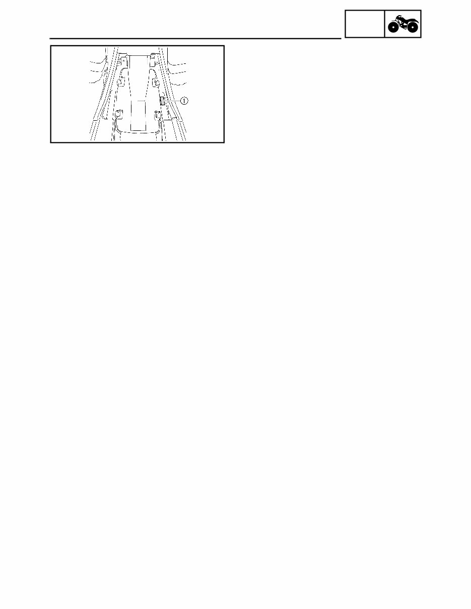
– 1 – GEN INFO GENERAL INFORMATION MACHINE IDENTIFICATION MODEL LABEL The model label 1 is affixed to the frame. This information will be needed to order spare parts. MACHINE IDENTIFICATION
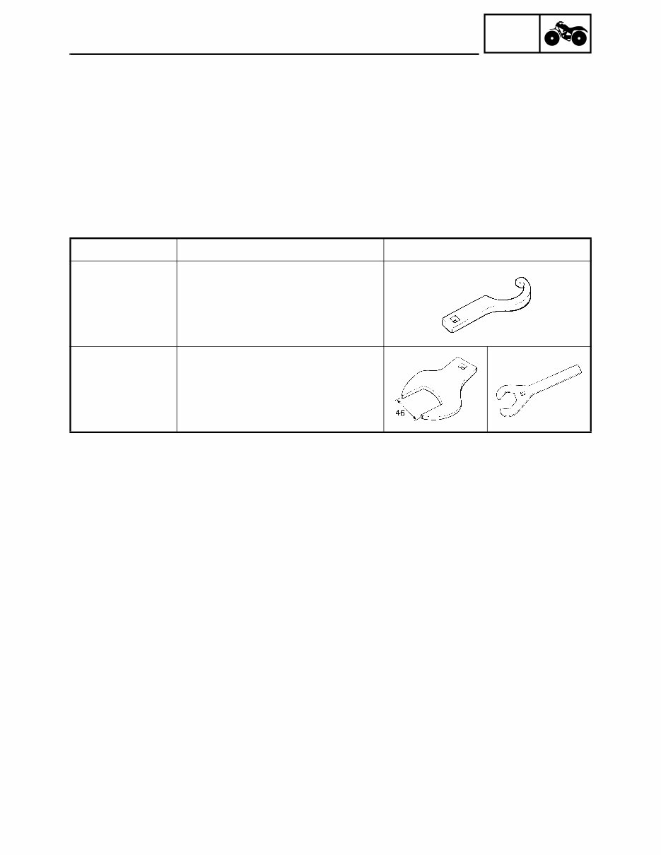
– 2 – GEN INFO SPECIAL TOOLS EB102001 SPECIAL TOOLS The following special tools are necessary for complete and accurate tune-up and assembly. Use only the appropriate special tools; this will help prevent damage caused by the use of inappropriate tools or improvised techniques. Special tools may differ by shape and part number from country to country. In such a case, two types are provided. When placing an order, refer to the list provided below to avoid any mistakes. For US and CDN P/N. YM-, YU-, YS-, YK-, ACC- Except for US and CDN P/N. 90890- Tool No. Tool name/How to use Illustration 90890-01443 YU-33975 Steering nut wrench This tool is needed to loosen and tighten the rear shock absorber locknut. 90890-01498 YM-37134 Axle nut wrench (46 mm) This tool is needed to loosen or tighten the rear axle nut.
– 3 – SPEC SPECIFICATIONS GENERAL SPECIFICATIONS Model YFM350S Model code number 5YT1 (For USA and Oceania) 5YT2 (For CDN) 5YT3 (For Europe) Dimensions Overall length 1,770 mm (69.7 in) Overall width 1,095 mm (43.1 in) Overall height 1,080 mm (42.5 in) Seat height 820 mm (32.3 in) Wheelbase 1,210 mm (47.6 in) Minimum ground clearance 115 mm (4.53 in) Basic weight With oil and full fuel tank 180.0 kg (397 lb) Minimum turning radius 3,100 mm (122 in) Engine Engine type Air-cooled 4-stroke, SOHC Cylinder arrangement Forward-inclined single cylinder Displacement 349.0 cm 3 (21.30 cu.in) Bore × stroke 83.0 × 64.5 mm (3.27 × 2.54 in) Compression ratio 9.20 : 1 Compression pressure 850 kPa (8.5 kg/cm 2 , 120.9 psi) at 350 r/min Starting system Electric starter Oil capacity Engine oil Periodic oil change 2.50 L (2.20 Imp qt, 2.64 US qt) With oil filter replacement 2.60 L (2.29 Imp qt, 2.75 US qt) Total amount 3.20 L (2.82 Imp qt, 3.38 US qt) Fuel Type Regular unleaded gasoline only (For CDN and Europe) Unleaded gasoline only (For USA and Oceania) Tank capacity 9.0 L (1.98 Imp gal, 2.38 US gal) Reserve amount 2.7 L (0.59 Imp gal, 0.71 US gal) Carburetor Type/manufacturer BSR36/MIKUNI GENERAL SPECIFICATIONS
Get your hands on the comprehensive 2004-2013 Yamaha Raptor 350 Service Manual and ATV Owners Maintenance Manual Set. This workshop repair manual is a must-have for both professional mechanics and DIY enthusiasts. It includes detailed procedures with pictures, exploded parts diagrams, troubleshooting, electrical information, and covers engine rebuild, valve jobs, transmission, and suspension. The set is guaranteed to match your specific ATV model and year, with all supplementary manuals required to cover all model years included. Additionally, the set comes with a printable Yamaha Raptor 350 Owner's Manual, featuring standard maintenance procedures, adjustments, schedules, control functions, specifications, and operating instructions. The service manual is bookmarked and keyword searchable, allowing for easy navigation and quick access to information. Whether you're a professional mechanic or a DIY enthusiast, this is the right manual for your 2004-2013 Yamaha Raptor 350. Don't miss out on this invaluable resource for maintaining and repairing your ATV.
Recently Viewed
5,521,897Happy Clients
2,594,462eManuals
1,120,453Trusted Sellers
15Years in Business
Price:
Actual Price:
2004-2013 Yamaha Raptor 350 Service Manual and ATV Owners Manual - Workshop Repair