

YAMAHA RAPTOR 125 YFM125 ATV Full Service & Repair Manual 2011-2012
What's Included?
Fast Download Speeds
Online & Offline Access
Access PDF Contents & Bookmarks
Full Search Facility
Print one or all pages of your manual

Yamaha Grizzly 125 Service Manual 2004-2013
This manual is comprised of a base manual for the 1989 Yamaha Breeze 125, and two
supplement manuals for that model, along with a supplement manual to make it
relevant for the 2004-2013 Yamaha Grizzly 125. Yamaha service manuals tend to
utilize this build-on-earlier models method when new models are similar to the old
models they are replacing. Use the links below or the bookmarks to the left to get to
the manual that covers your model.
1989 Yamaha Breeze 125 base manual
2000 Yamaha Breeze 125 supplement manual
2002 Yamaha Breeze 125 supplement manual
2004-2013 Yamaha Grizzly 125 supplement manual
_YAMAHA
LIT-11616-06-75
3FA-28197-10
YFA1W
SERVICE MANUAL
© 1988 by Yamaha Motor
Corporation, U.S.A.
1st edition, November 1988
All rights reserved. Any reprinting or
unauthorized use without the written
permission of Yamaha Motor
Corporation, U.S.A. is expressly
Prohibited. Printed in U.S.A.
LIT-11616-06-75
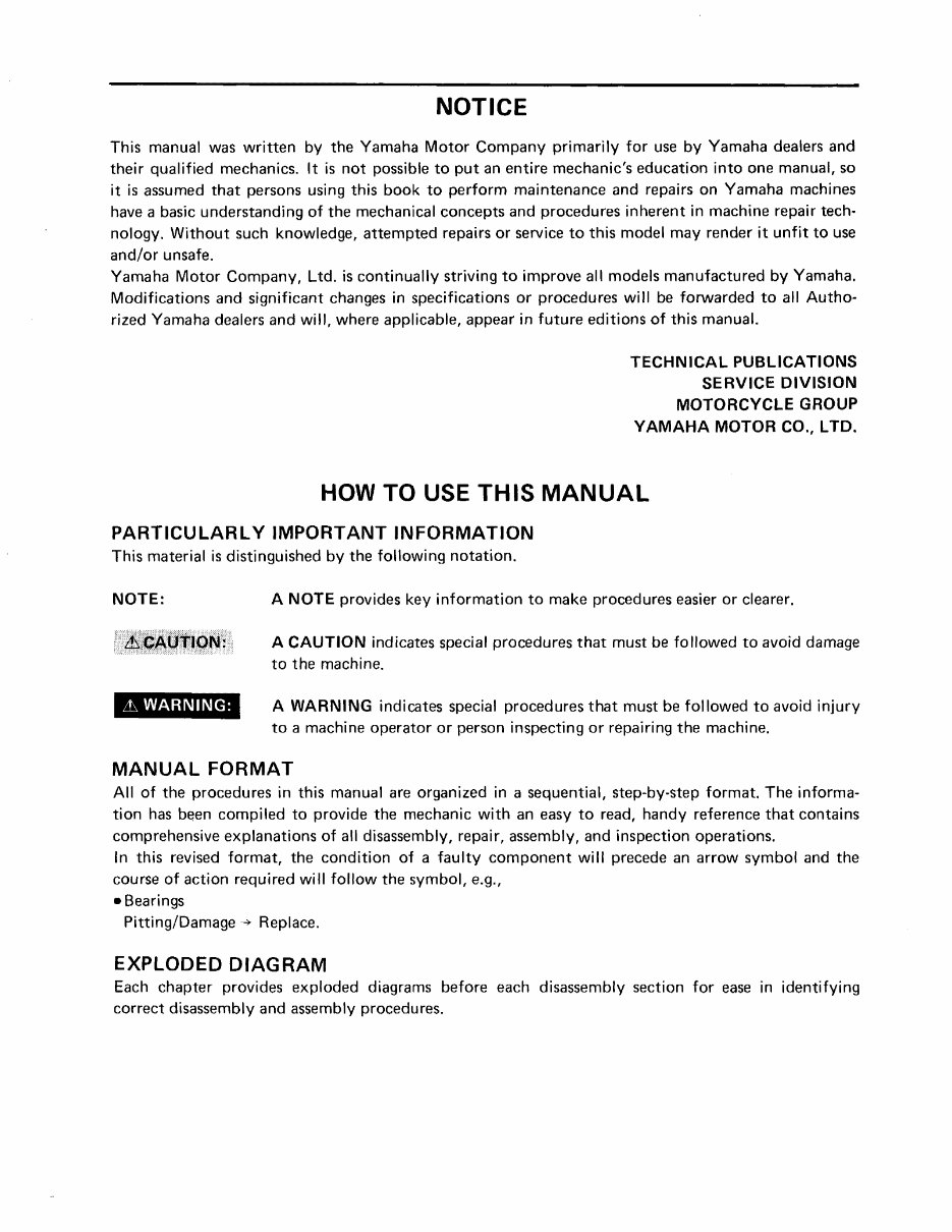
NOTICE
This manual was written by the Yamaha Motor Company primarily for use by Yamaha dealers and
their qualified mechanics. It is not possible to put an entire mechanic's education into one manual, so
it is assumed that persons using this book to perform maintenance and repairs on Yamaha machines
have a basic understanding of the mechanical concepts and procedures inherent in machine repair tech·
nology. Without such knowledge, attempted repairs or service to this model may render it unfit to use
and/or unsafe.
Yamaha Motor Company, Ltd. is continually striving to improve all models manufactured by Yamaha.
Modifications and significant changes in specifications or procedures will be forwarded to all Autho·
rized Yamaha dealers and will, where applicable, appear in future editions of this manual.
TECHNICAL PUBLICATIONS
SERVICE DIVISION
MOTORCYCLE GROUP
YAMAHA MOTOR CO., LTO.
HOW TO USE THIS MANUAL
PARTICULARLY IMPORTANT INFORMATION
This material is distinguished by the following notation.
NOTE:
Lh WARNING:
A NOTE provides key information to make procedures easier or clearer.
A CAUTION indicates special procedures that must be followed to avoid damage
to the machine.
A WARNING indicates special procedures that must be followed to avoid injury
to a machine operator or person inspecting or repairing the machine.
MANUAL FORMAT
All of the procedures in this manual are organized in a sequential, step-by·step format. The informa·
tion has been compiled to provide the mechanic with an easy to read, handy reference that contains
comprehensive explanations of all disassembly, repair, assembly, and inspection operations.
In this revised format, the condition of a faulty component will precede an arrow symbol and the
course of action required will follow the symbol, e.g.,
• Bearings
Pitting/Damage ~ Replace.
EXPLODED DIAGRAM
Each chapter provides exploded diagrams before each disassembly section for ease in identifying
correct disassembly and assembly procedures.
CD ®
I ~ EF~ 101ta 1
ISPECI p~1
® ®
1~6JlilNl
ENG
••
® ®
ICOOll ~I ICARBI f I
(j)
®
IORIVI-ra-1 ICHASI~I
®
@
I ElECI iii I
I~~~~I? I
@
~
@
~
@
~
@
~
@
~
@
I0l
@
[11
@
,
iLT)
@
1
®
i
®
1
-
Gl e m
@ @
®
~ ~ ~
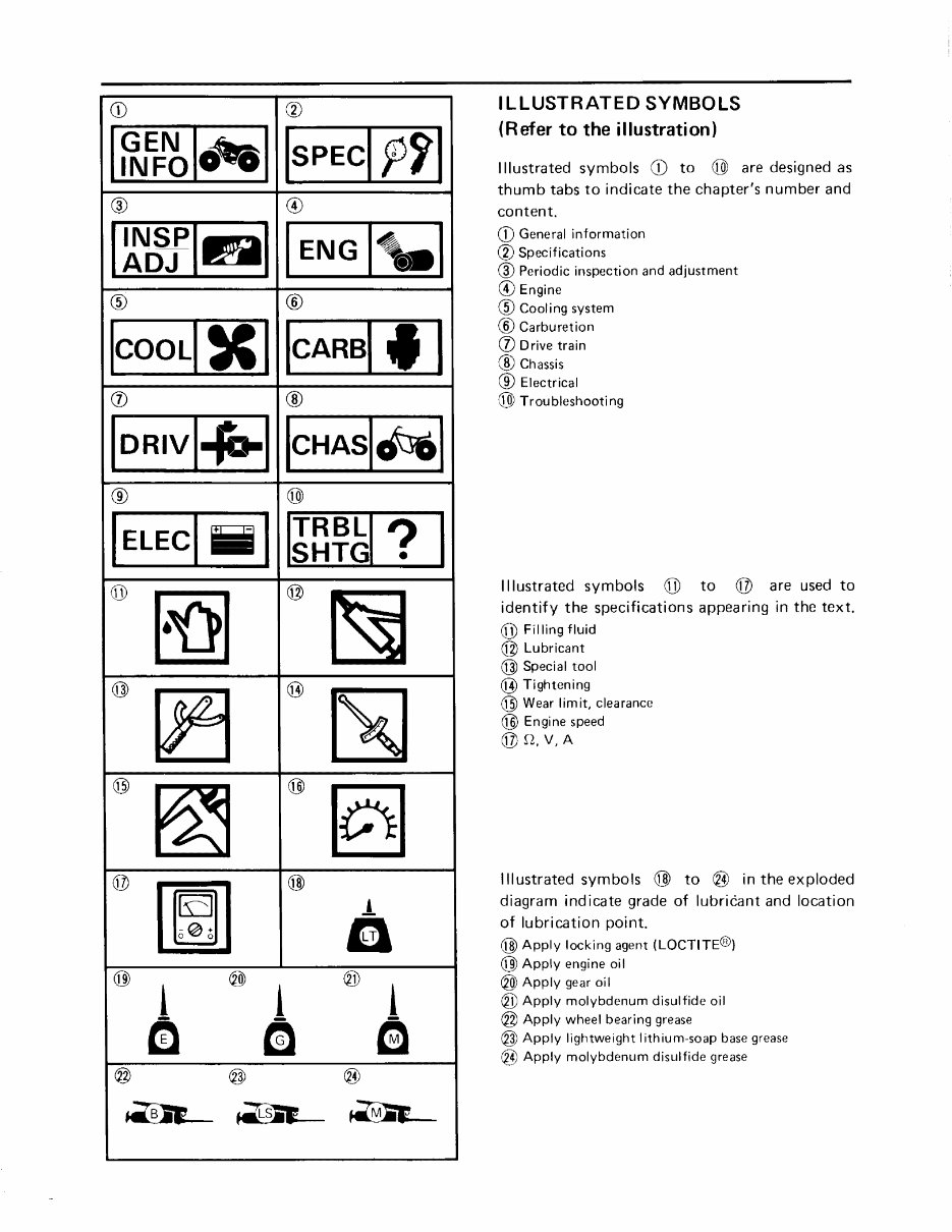
ILLUSTRATED SYMBOLS
(Refer to the illustration)
Illustrated symbols CD to ® are designed as
thumb tabs to indicate the chapter's number and
content.
CD General information
® Specifications
® Periodic inspection and adjustment
® Engine
® Cool i ng system
® Carburetion
(j) 0 rive tra in
® Chassis
® Electrical
@ Troubleshooting
Illustrated symbols @ to @ are used to
identify the specifications appearing in the text.
@ Filling fluid
@ Lubricant
@ Special tool
@ Tightening
@ Wear lim it, clearance
@ Engine speed
@n,V,A
Illustrated symbols @ to ® in the exploded
diagram indicate grade of lubricant and location
of lubrication point.
@ Apply locking agent (LOCTITE@)
@ Apply engine oil
® Apply gear oil
® Apply molybdenum disulfide oil
@ Apply wheel bearing grease
@ Apply lightweight lithium-soap base grease
® Apply molybdenum disulfide grease
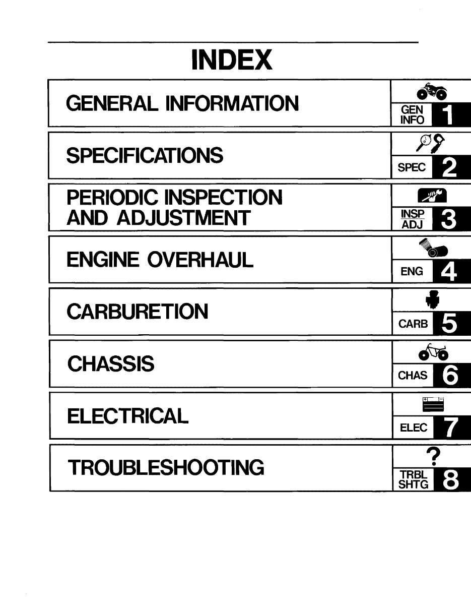
INDEX
GENERAL INFORMATION
SPECIFICATIONS
PERIODIC INSPECTION
AND ADJUSTMENT
ENGINE OVERHAUL
CARBURETION
CHASSIS
ELECTRICAL
TROUBLESHOOTING
ott.
I---
GEN
INFO
SPEC
II!JJ
1---
INSP
ADJ
ENG
CARS
CHAS
ELEC
?
I---~.
TRBL
SHTG
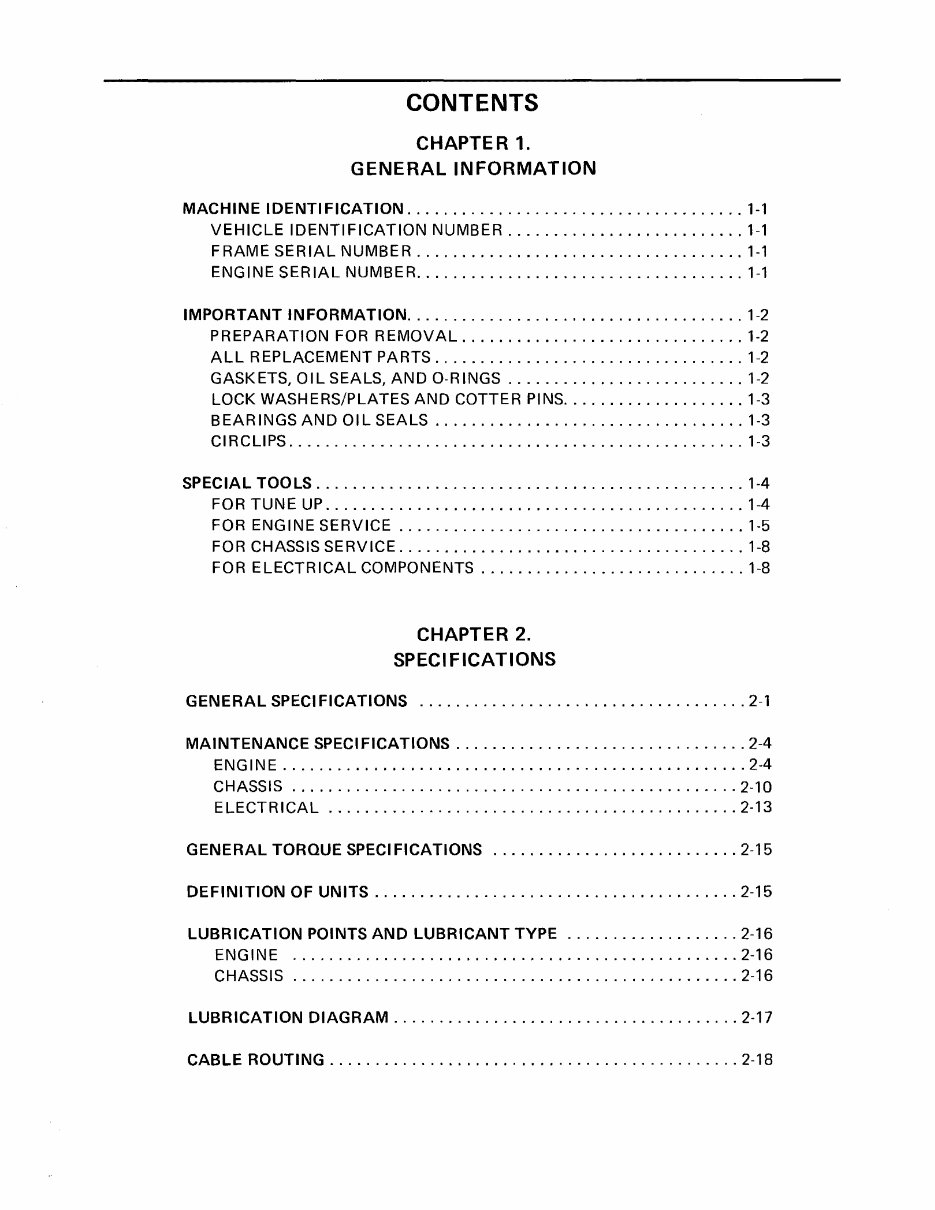
CONTENTS
CHAPTER 1.
GENERAL INFORMATION
MACHINE IDENTIFICATION ..................................... 1-1
VEHICLE IDENTIFICATION NUMBER .......................... 1-1
FRAME SERIAL NUMBER .................................... 1-1
ENGINE SERIAL NUMBER .. " ................. ____ . _ .. _ . ___ . _ 1-1
IMPORTANT INFORMATION. _ ..... _ ............................. 1-2
PREPARATION FOR REMOVAL ............. " ................ 1-2
ALL REPLACEMENT PARTS .................................. 1-2
GASKETS, OIL SEALS, AND O-RINGS ....... _ .................. 1-2
LOCK WASHERS/PLATES AND COTTER PINS .. " ................ 1-3
BEARINGS AND OIL SEALS ................ " ................ 1-3
CI RCLIPS ........ _ ........................................ _ 1-3
SPECIAL TOOLS .................................... _ ......... _1-4
FOR TUNE UP ........................... _ . __ ............... 1-4
FOR ENGINE SERVICE ...................................... 1-5
FOR CHASSIS SERVICE ...................................... 1-8
FOR ELECTRICAL COMPONENTS .......................... _ .. 1-8
CHAPTER 2.
SPECIFICATIONS
GENERAL SPECIFICATIONS .................................... 2-1
MAINTENANCE SPECIFICATIONS ...................... , ... , ..... 2-4
ENGINE ................................................... 2-4
CHASSIS ................................................. 2-10
ELECTRICAL ............................................. 2-13
GENERAL TORQUE SPECIFICATIONS ........................... 2-15
DEFINITION OF UNITS ........................................ 2-15
LUBRICATION POINTS AND LUBRICANT TYPE ................... 2-16
ENGINE ................................................. 2-16
CHASSIS ................................................. 2-16
LUBRICATION DIAGRAM ...................................... 2-17
CABLE ROUTING ............................................. 2-18
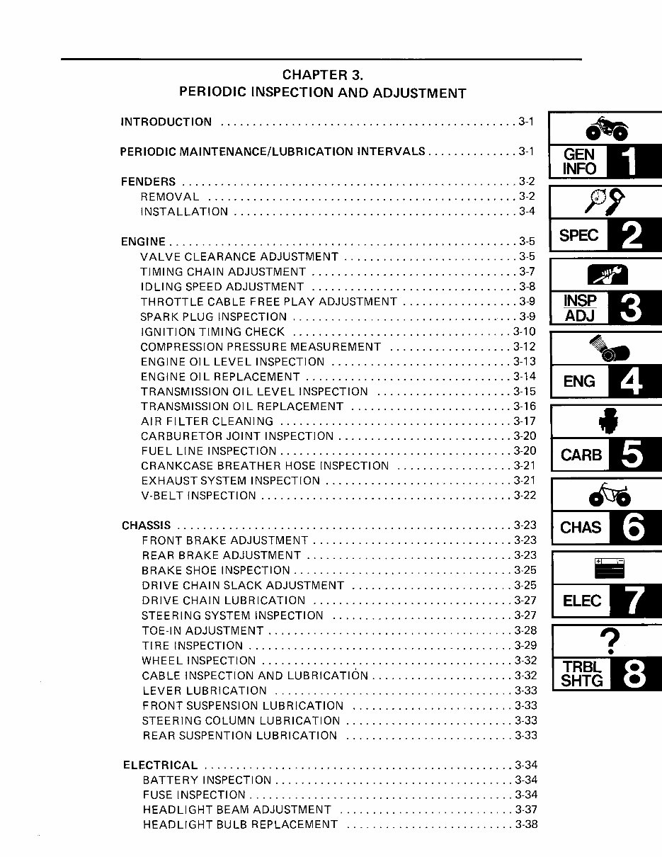
CHAPTER 3.
PERIODIC INSPECTION AND ADJUSTMENT
INTRODUCTION .............................................. 3-1
PERIODIC MAINTENANCE/LUBRICATION INTERVALS .............. 3-1
FENDERS .................................................... 3-2
REMOVAL ................................................ 3-2
INSTALLATION ............................................ 3-4
ENGINE ...................................................... 3-5
VALVE CLEARANCE ADJUSTMENT ........................... 3-5
TIMING CHAIN ADJUSTMENT ................................ 3-7
IDLING SPEED ADJUSTMENT ................................ 3-8
THROTTLE CABLE FREE PLAY ADJUSTMENT .................. 3-9
SPARK PLUG INSPECTION ................................... 3-9
IGNITION TIMING CHECK .................................. 3-10
COMPRESSION PRESSURE MEASUREMENT ................... 3-12
ENGINE 01 L LEVEL INSPECTION ............................ 3-13
ENGINE OIL REPLACEMENT ................................ 3-14
TRANSMISSION OIL LEVEL INSPECTION ..................... 3-15
TRANSMISSION OIL REPLACEMENT ......................... 3-16
AIR FILTER CLEANING .................................... 3-17
CARBURETOR JOINT INSPECTION ........................... 3-20
FUEL LINE INSPECTION .................................... 3-20
CRANKCASE BREATHER HOSE INSPECTION .................. 3-21
EXHAUST SYSTEM INSPECTION ............................. 3-21
V-BELT INSPECTION ....................................... 3-22
CHASSIS .................................................... 3-23
FRONT BRAKE ADJUSTMENT ............................... 3-23
ott.
~G~E-N-
INFO
SPEC
IPjJ
~IN~S~P-
ADJ
~ .•
..---~
ENG
•
CARB
CHAS
REAR BRAKE ADJUSTMENT ................................ 3-23 ~
BRAKE SHOE INSPECTION .................................. 3-25 ==
DRIVE CHAIN SLACK ADJUSTMENT ......................... 3-25
DRIVE CHAIN LUBRiCATION ............................... 3-27
STEERING SYSTEM INSPECTION ............................ 3-27
TOE-IN ADJUSTMENT ...................................... 3-28
TIRE INSPECTION ......................................... 3-29
WHEEL INSPECTION ....................................... 3-32
CABLE INSPECTION AND LUBRiCATION ...................... 3-32
LEVER LUBRICATION ..................................... 3-33
FRONT SUSPENSION LUBRICATION ......................... 3-33
STEERING COLUMN LUBRICATION .......................... 3-33
REAR SUSPENTION LUBRICATION .......................... 3-33
ELECTRICAL ................................................ 3-34
BATTERY INSPECTION ..................................... 3-34
FUSE INSPECTION ......................................... 3-34
HEADLIGHT BEAM ADJUSTMENT ........................... 3-37
HEADLIGHT BULB REPLACEMENT .......................... 3-38
ELEC
?
•
..----
TRBL
SHTG
CHAPTER 4
ENGINE OVERHAUL
ENGINE REMOVAL . ........................................... 4-1
ENG I N E 0 I L ....................................... , , .. , . , . 4-1
TRANSMISSION OIL. ........................................ 4-1
FENDERS .................................................. 4-1
CARBURETOR ............................................. 4-1
MUFF LER ................................................. 4-2
STARTING MOTOR .......................................... 4-3
LEADS AN D HOSES ......................................... 4-3
ENGINE REMOVAL ......................................... 4-3
ENGINE DISASSEMBLY . ........... , ..................... , . , .... 4-5
CYLINDER HEAD, CYLINDER AND PISTON ..................... 4-5
PRIMARY SHEAVE AND SECONDARY SHEAVE .................. 4-7
ELECTRIC STARTING DRIVE ........................ , ........ 4-9
SHIFT LEVER ............................................. 4-10
CDI MAGNETO ............................................ 4-10
OIL PU M P. . . . . . . . . . . . . . . . . . . . . . . . . . . . . . . . . . . . . . . . . . . . . . . . . 4-11
TIMING CHAIN ............................................ 4-12
CRANKCASE (RIGHT) .......................... , ......... , .4-12
SHIFTER AND TRANSMISSION ............................... 4-13
CRANKSHAFT AND BALANCER .............................. 4-14
CAMSHAFT, ROCKER ARM AND VALVE ...................... 4-14
INSPECTION AND REPAIR .. ................................... 4-17
CYLINDER HEAD .......................................... 4-17
VA LV E SEAT .............................................. 4-18
VALVE AND VALVE GUIDE ................................. 4-21
CAMSHAFT ............................................... 4-22
ROCKER ARM AND ROCKER ARM SHAFT ..................... 4-23
VALVE SPRING ............................................ 4-24
TIMING CHAIN, CHAIN GUIDE AND SPROCKET ................ 4-24
CYLINDER AND PISTON .................................... 4-25
PISTON RING ............................................. 4·27
PISTON PIN ............................................... 4·27
CRANKSHAFT AND CONNECTING ROD ....................... 4-28
ELECTRIC STARTER DRIVES ................................ 4·29
CLUTCH .................................................. 4-30
TRANSMISSION AND SHIFTER ............................... 4-31
PRIMARY SHEAVE AND SECONDARY SHEAVE ................. 4-32
V-BELT .... ',' ............................................. 4-33
OIL PUMP AND STRAINER ........................ , ......... 4-34
OIL DELIVERY PIPE ............ , ........................... 4-34
CRANKCASE .............................................. 4-35
BEAR INGS AND 01 L SEALS ................................. 4-35
CIRCLIPS AND WASHERS ................................... 4-35
ENGINE ASSEMBLY AND ADJUSTMENT .......................... 4-36
CAMSHAFT, ROCKER ARM AND VALVE ...................... 4-36
CRANKSHAFT AND BALANCER .............................. 4-37
SHIFTER AND TRANSMISSION ............................... 4-37
CRANKCASE (RIGHT) ...................................... 4-38
TIMING CHAIN ............................................ 4-43
OIL PUMP .. " ............................................. 4-43
CDI MAGNETO ............................................ 4-43
SHIFT LEVER .......... " ................................. 4-44
ELECTRIC STARTING DRIVE ................................ 4-45
PRIMARY SHEAVE AND SECONDARY SHEAVE ................. 4-45
CYLINDER HEAD, CYLINDER AND PISTON .................... 4-47
REMOUNTING ENGINE ..................................... 4-55
CHAPTER 5.
CARBURETION
CARBURETOR ................................................ 5-1
SECTIONAL VIEW .......................................... 5-2
REMOVAL ................................................ 5-3
DISASSEMBLY ............................................. 5-4
INSPECTION ............................................... 5-5
ASSEMBLY ................................................ 5-7
INSTALLATION ............................................ 5-7
FLOAT HEIGHT ADJUSTMENT .............................. 5-8
FUEL LEVEL ADJUSTMENT ................................. 5-9
CHAPTER 6.
CHASSIS
FRONT WHEEL ............................................... 6-1
REMOVAL ................................................ 6-2
INSPECTION ............................................... 6-3
INSTALLATION ............................................ 6-5
REAR WHEEL ................................................. 6-8
REMOVAL ................................................ 6-9
INSPECTION .............................................. 6-12
INSTALLATION ........................................... 6-15
FRONT SUSPENSION .......................................... 6-18
REMOVAL ............................................... 6-19
INSPECTION .............................................. 6-20
INSTALLATION ........................................... 6-21
.-.
1--___ --
GEN
INFO
SPEC
fi
INSP
ADJ
~ .•
1---- .... ;
ENG
•
CARB
~
1-----
CHAS
ELEC
?
t----........ ..... --.
TRBL
SHTG
You're Reading a Preview
What's Included?
Fast Download Speeds
Online & Offline Access
Access PDF Contents & Bookmarks
Full Search Facility
Print one or all pages of your manual
$31.99
$41.99
Viewed 79 Times Today


Secure transaction
What's Included?
Fast Download Speeds
Online & Offline Access
Access PDF Contents & Bookmarks
Full Search Facility
Print one or all pages of your manual
$31.99
$41.99
- This complete factory service repair workshop manual is available for instant access on your computer, tablet, or smartphone.
- It covers all repairs, servicing, and troubleshooting procedures with detailed photos and diagrams.
- Professional mechanics and technicians use this manual, which contains step-by-step instructions and highly detailed exploded diagrams and pictures.
- You have the option to print out a single page or the entire manual.
- This manual can be used on multiple computers without any limitations or trial periods.
- There is no expiry date, renewal fee, or need to pay extra for continued use.
- It is fully compatible with Windows and MAC computers.
For more information, please click the button below.


