

2018 Yamaha KODIAK 700 EPS 4WD SE Service & Repair Manual
What's Included?
Fast Download Speeds
Online & Offline Access
Access PDF Contents & Bookmarks
Full Search Facility
Print one or all pages of your manual
Repair&ServiceManual
ServiceManual
e4~.
2=>“P
;~y~~
=-
.
a=>
-~
~~
eas20002
YFM70KDXH/YFM70KDHH/
YFM70KPXH/YFM70KPAH/
YFM70KPHH/YFM70KPSH
SERVICEMANUAL
©2016byYamahaMotorCorporation,U.S.A.
Firstedition,June2016
Allrightsreserved.
Anyreproductionorunauthorizeduse
withoutthewrittenpermissionof
YamahaMotorCorporation,U.S.A.
isexpresslyprohibited.
PrintedinU.S.A.
eBs20009
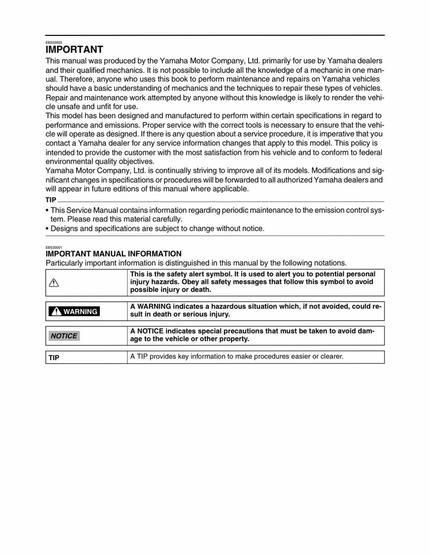
IMPORTANT
ThismanualwasproducedbytheYamahaMotorCompany,Ltd.primarilyforusebyYamahadealers
andtheirqualifiedmechanics.Itisnotpossibletoincludealltheknowledgeofamechanicinoneman-
ual.Therefore,anyonewhousesthisbooktoperformmaintenanceandrepairsonYamahavehicles
shouldhaveabasicunderstandingofmechanicsandthetechniquestorepairthesetypesofvehicles.
Repairandmaintenanceworkattemptedbyanyonewithoutthisknowledgeislikelytorenderthevehi-
cleunsafeandunfitforuse.
Thismodelhasbeendesignedandmanufacturedtoperformwithincertainspecificationsinregardto
performanceandemissions.Properservicewiththecorrecttoolsisnecessarytoensurethatthevehi-
clewilloperateasdesigned.Ifthereisanyquestionaboutaserviceprocedure,itisimperativethatyou
contactaYamahadealerforanyserviceinformationchangesthatapplytothismodel.Thispolicyis
intendedtoprovidethecustomerwiththemostsatisfactionfromhisvehicleandtoconformtofederal
environmentalqualityobjectives.
YamahaMotorCompany,Ltd.iscontinuallystrivingtoimproveallofitsmodels.Modificationsandsig-
nificantchangesinspecificationsorprocedureswillbeforwardedtoallauthorizedYamahadealersand
willappearinfutureeditionsofthismanualwhereapplicable.
TIP
*ThisServiceManualcontainsinformationregardingperiodicmaintenancetotheemissioncontrolsys-
tem.Pleasereadthismaterialcarefully.
*Designsandspecificationsaresubjecttochangewithoutnotice.
EBS20001
IMPORTANTMANUALINFORMATION
Particularlyimportantinformationisdistinguishedinthismanualbythefollowingnotations.
Thisisthesafetyalertsymbol.Itisusedtoalertyoutopotentialpersonal
ainjuryhazards.Obeyallsafetymessagesthatfollowthissymboltoavoid
possibleinjuryordeath.
AWARNINGindicatesahazardoussituationwhich,ifnotavoided,couldre-
AWARNINGsultindeathorseriousinjury.
ANOTICEindicatesspecialprecautionsthatmustbetakentoavoiddam-
NOTICEagetothevehicleorotherproperty.
TIPATIPprovideskeyinformationtomakeprocedureseasierorclearer.
Easco00e
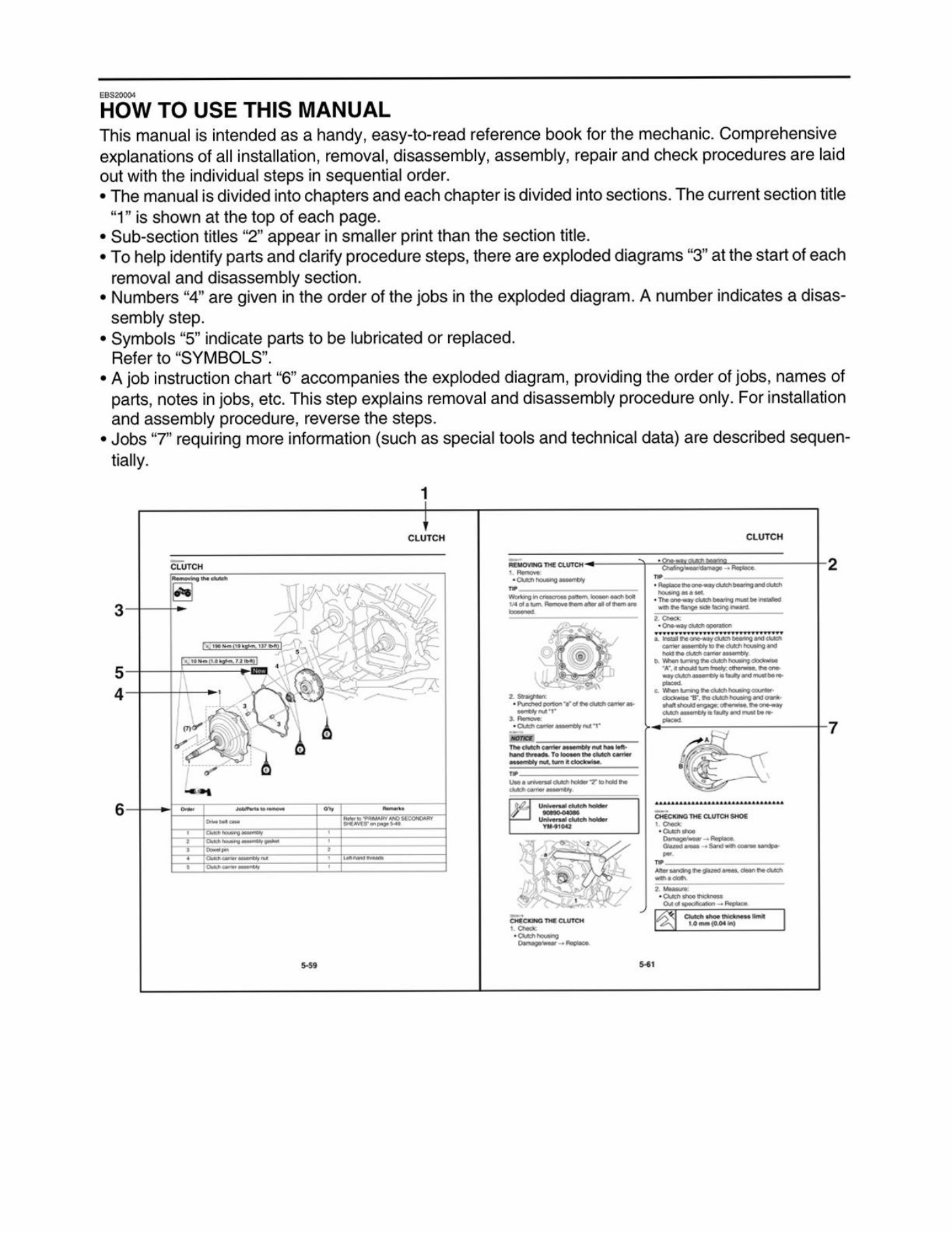
HOWTOUSETHISMANUAL
Thismanualisintendedasahandy,easy-to-readreferencebookforthemechanic.Comprehensive
explanationsofallinstallation,removal,disassembly,assembly,repairandcheckproceduresarelaid
outwiththeindividualstepsinsequentialorder.
*Themanualisdividedintochaptersandeachchapterisdividedintosections.Thecurrentsectiontitle
“1”isshownatthetopofeachpage.
*Sub-sectiontitles“2”appearinsmallerprintthanthesectiontitle.
*Tohelpidentifypartsandclarifyproceduresteps,thereareexplodeddiagrams“3”atthestartofeach
removalanddisassemblysection.
*Numbers“4”aregivenintheorderofthejobsintheexplodeddiagram.Anumberindicatesadisas-
semblystep.
*Symbols“5”indicatepartstobelubricatedorreplaced.
Referto“SYMBOLS”.
«Ajobinstructionchart“6”accompaniestheexplodeddiagram,providingtheorderofjobs,namesof
parts,notesinjobs,etc.Thisstepexplainsremovalanddisassemblyprocedureonly.Forinstallation
andassemblyprocedure,reversethesteps.
*Jobs“7”requiringmoreinformation(suchasspecialtoolsandtechnicaldata)aredescribedsequen-
tially.
i
cLuTcHCLUTCH
eturcnFeinomeTeCUTE
FeriawenssCicntexangasey
3=-Steenenaeaten ae
5—}———___
a
oe.
6}+Ioy
+Cuancosncrass
‘chsoekeik
2x]“taimmiooeiy
559se
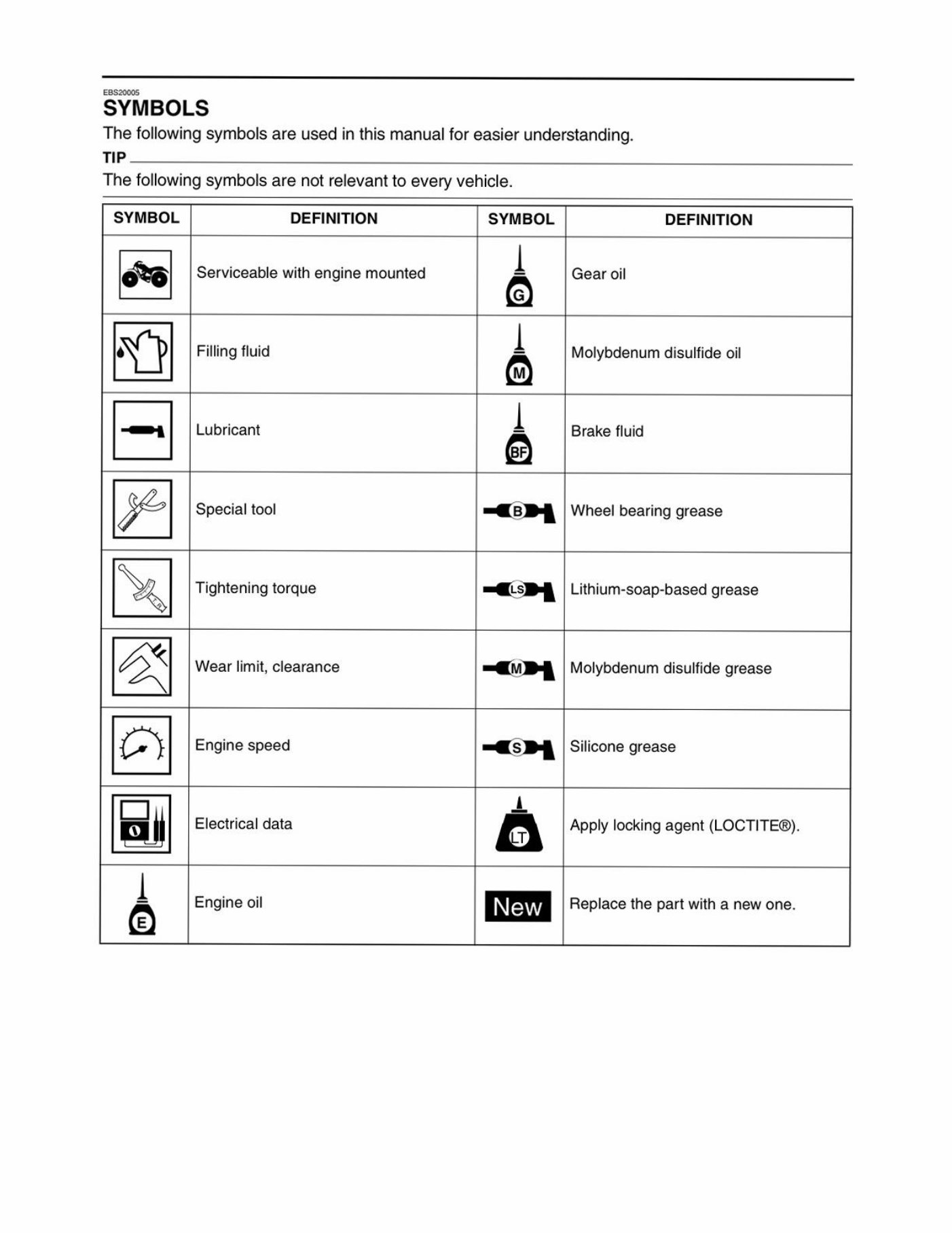
SYMBOLS
Thefollowingsymbolsareusedinthismanualforeasierunderstanding.
TIP
Thefollowingsymbolsarenotrelevanttoeveryvehicle.
SYMBOL
DEFINITION SYMBOL DEFINITION
0%)
Serviceablewithenginemounted
Gearoil
Dp |B |H—
FillingfluidMolybdenumdisulfideoil
LubricantBrakefluid
Specialtool=a5P4Wheelbearinggrease
Tighteningtorque Lithium-soap-basedgrease
Wearlimit,clearance Molybdenumdisulfidegrease
Enginespeed
Siliconegrease
Electricaldata
Applylockingagent(LOCTITE®).
e- (S| DI LIN We
Engineoil
Replacethepartwithanewone.

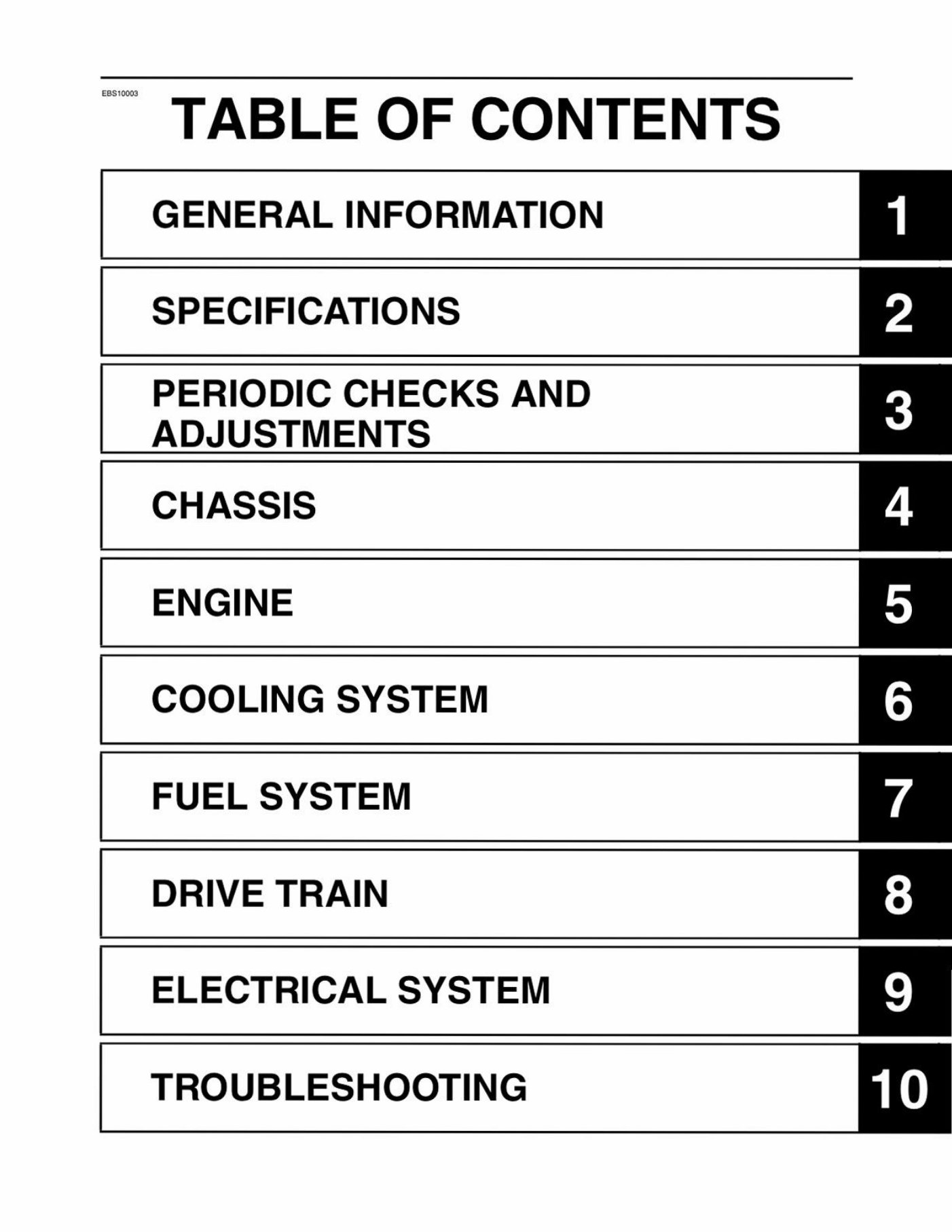
~TABLEOFCONTENTS
GENERALINFORMATION
SPECIFICATIONS
PERIODICCHECKSAND
ADJUSTMENTS
CHASSIS
ENGINE
COOLINGSYSTEM
FUELSYSTEM
DRIVETRAIN
ELECTRICALSYSTEM
TROUBLESHOOTING
lelel~folal=le[s| =

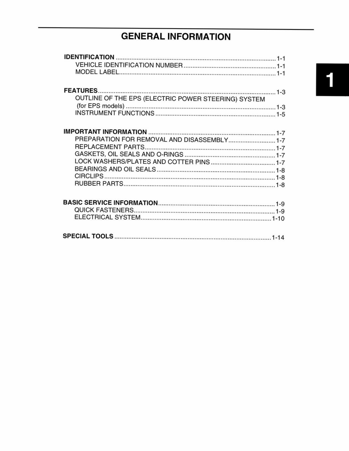
IDENTIFICATION
VEHICLEIDENTIFICATIONNUMBER.
MODELLABELivsicsssisarsossses
FEATURES..
OUTLINETHEEPS(ELECTRICPOWERSTEERING)SYSTEM
(forEPSmodels)
INSTRUMENTFUNCTIONS.
IMPORTANTINFORMATION....
PREPARATIONFORREMO)
REPLACEMENTPARTS..........c:eeeee
GASKETS,OILSEALSANDO-RINGS.
LOCKWASHERS/PLATESANDCOTTERPINS
BEARINGSANDOILSEALS
CIRCLIPS..........
RUBBERPARTS.
ooovvuNy
BASICSERVICEINFORMATION
QUICKFASTENERS
ELECTRICALSYST!
SPECIALTOOLSsicssczvsscasescssscusesarssetnsstaseansneraseriiereestivacsiosswsssiosrsvasiecsessasiees1-14
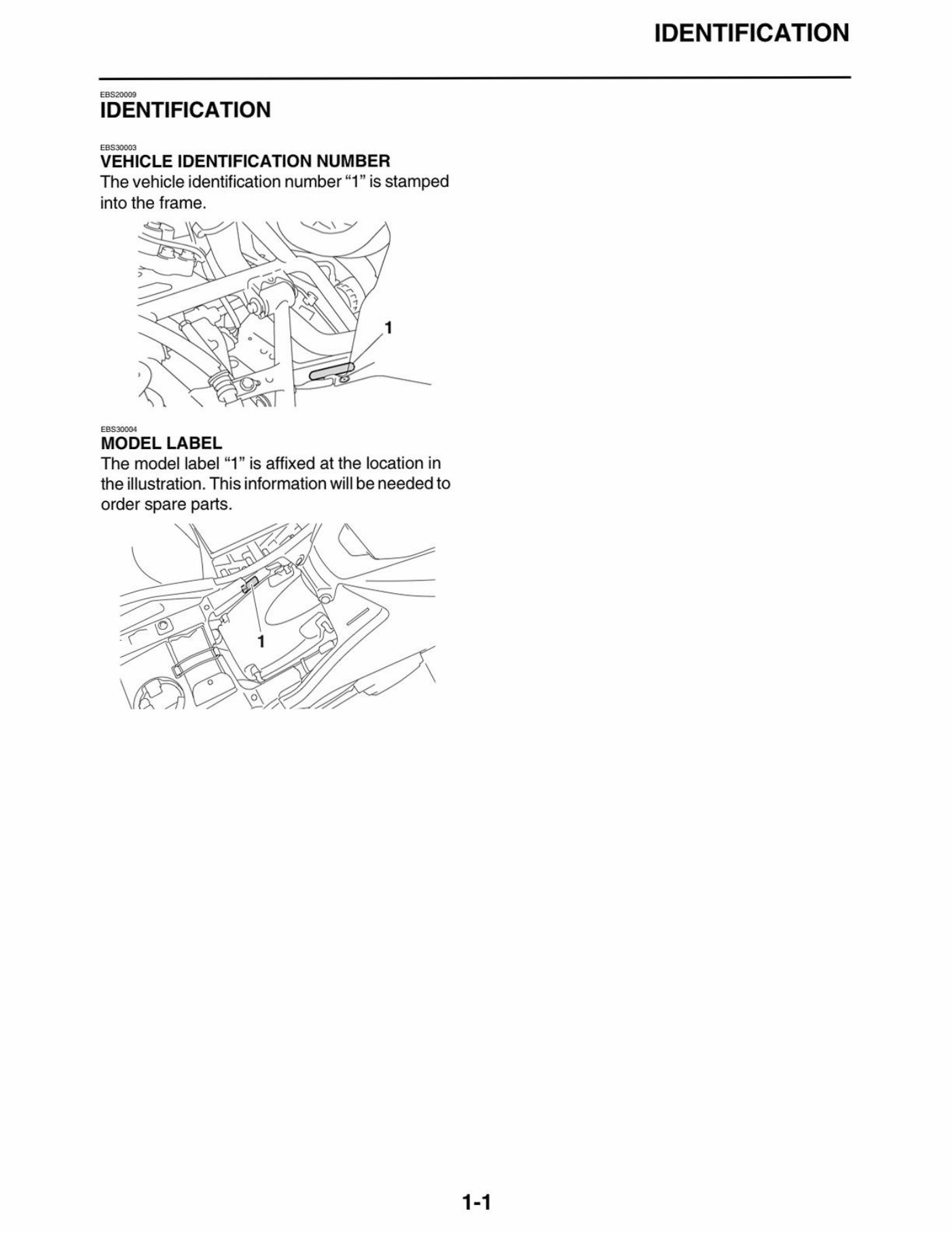
IDENTIFICATION
eBss0003
VEHICLEIDENTIFICATIONNUMBER
Thevehicleidentificationnumber“1”isstamped
intotheframe.
MODELLABEL
Themodellabel“1”isaffixedatthelocationin
theillustration.Thisinformationwillbeneededto
orderspareparts.
1-1
IDENTIFICATION
You're Reading a Preview
What's Included?
Fast Download Speeds
Online & Offline Access
Access PDF Contents & Bookmarks
Full Search Facility
Print one or all pages of your manual
$57.99
Viewed 91 Times Today


Secure transaction
What's Included?
Fast Download Speeds
Online & Offline Access
Access PDF Contents & Bookmarks
Full Search Facility
Print one or all pages of your manual
$57.99
The Yamaha KODIAK 700 EPS 4WD SE is a reliable off-road vehicle, and this comprehensive service and repair manual provides the technical guidance you need to maintain or fix it.
- This manual covers a range of essential topics, from troubleshooting common issues to performing routine maintenance tasks.
- It offers detailed instructions for repairs, including step-by-step procedures and diagrams, making it suitable for both professional mechanics and DIY enthusiasts.
- The manual provides in-depth information on the vehicle's systems, components, and specifications, giving you a deep understanding of its inner workings.
Whether you're a seasoned mechanic or a novice enthusiast, this service and repair manual is an invaluable resource for keeping your Yamaha KODIAK 700 EPS 4WD SE in top condition.


