Yamaha YFM660 Grizzly 2002-2007 Service Repair Manual
What's Included?
Lifetime Access
Fast Download Speeds
Online & Offline Access
Access PDF Contents & Bookmarks
Full Search Facility
Print one or all pages of your manual
YFM660 2002-2006 SERVICE MANUAL 2by Yamaha Motor Co., Ltd. First edition, May 2001 All rights reserved. Any reproduction or unauthorized use without the written permission of Yamaha Motor Co., Ltd. is expressly prohibited.
EB001000 NOTICE This manual was produced by the Yamaha Motor Company primarily for use by Yamaha dealers and their qualified mechanics. It is not possible to include all the knowledge of a mechanic in one manual, so it is assumed that anyone who uses this book to perform maintenance and repairs on Yamaha machine has a basic understanding of the mechanical ideas and the procedures of machine repair. Repairs attempted by anyone without this knowledge are likely to render the machine unsafe and unfit for use. Yamaha Motor Company, Ltd. is continually striving to improve all its models. Modifications and sig- nificant changes in specifications or procedures will be forwarded to all authorized Yamaha dealers and will appear in future editions of this manual where applicable. NOTE: Designs and specifications are subject to change without notice. IMPORTANT INFORMATION Particularly important information is distinguished in this manual by the following notations. The Safety Alert Symbol means ATTENTION! BECOME ALERT! YOUR SAFETY IS INVOLVED! Failure to follow WARNING instructions could result in severe injury or death to the machine operator, a bystander or a person inspecting or repairing the machine. A CAUTION indicates special precautions that must be taken to avoid dam- age to the machine. A NOTE provides key information to make procedures easier or clearer. WARNING CAUTION: NOTE:
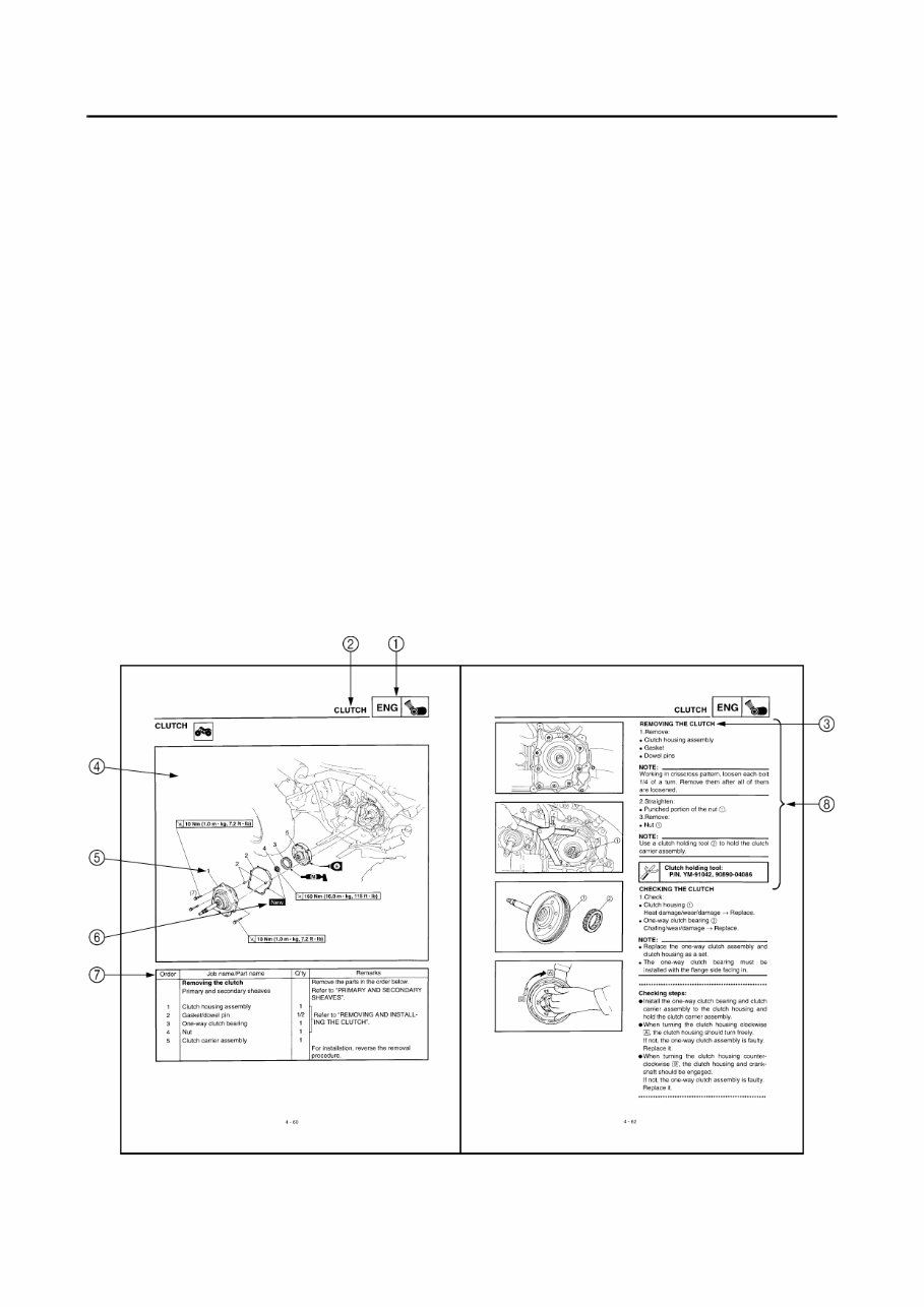
EB002000 HOW TO USE THIS MANUAL MANUAL ORGANIZATION This manual consists of chapters for the main categories of subjects. (See “Illustrated symbols”) 1st title 1: This is the title of the chapter with its symbol in the upper right corner of each page. 2nd title 2: This title indicates the section of the chapter and only appears on the first page of each section. It is located in the upper left corner of the page. 3rd title 3: This title indicates a sub-section that is followed by step-by-step procedures accompa- nied by corresponding illustrations. EXPLODED DIAGRAMS To help identify parts and clarify procedure steps, there are exploded diagrams at the start of each removal and disassembly section. 1. An easy-to-see exploded diagram 4 is provided for removal and disassembly jobs. 2. Numbers 5 are given in the order of the jobs in the exploded diagram. A number that is enclosed by a circle indicates a disassembly step. 3. An explanation of jobs and notes is presented in an easy-to-read way by the use of symbol marks 6. The meanings of the symbol marks are given on the next page. 4. A job instruction chart 7 accompanies the exploded diagram, providing the order of jobs, names of parts, notes in jobs, etc. 5. For jobs requiring more information, the step-by-step format supplements 8 are given in addition to the exploded diagram and the job instruction chart.
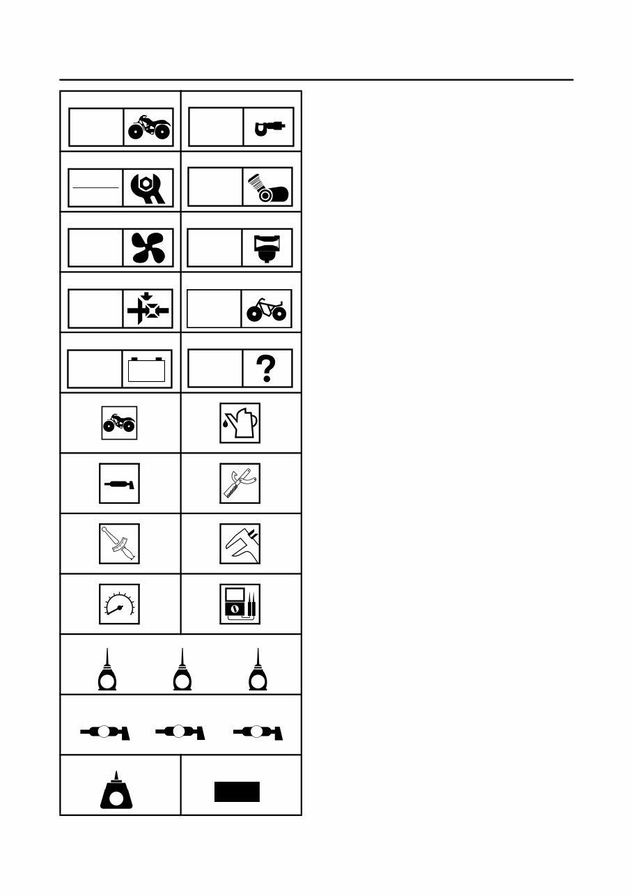
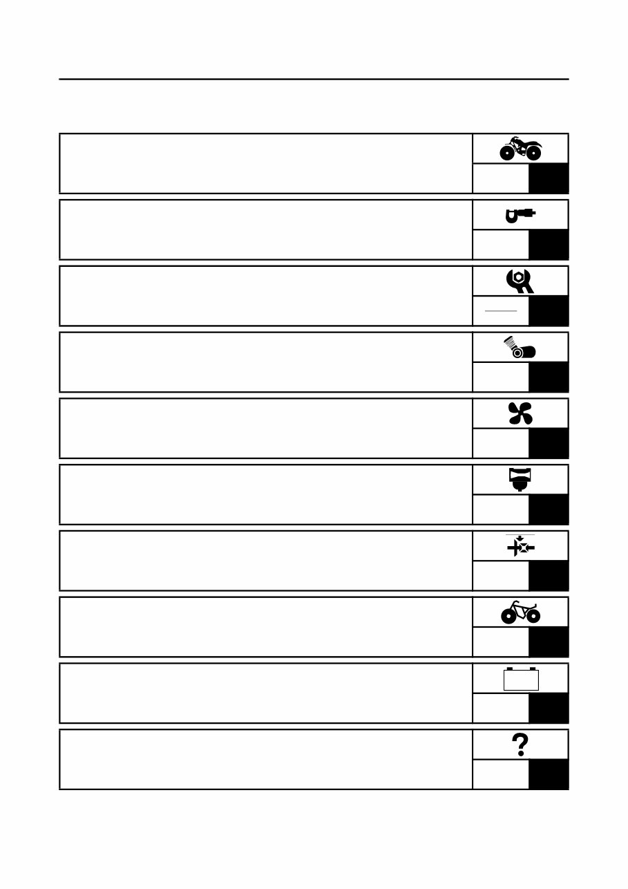
EB003000 ILLUSTRATED SYMBOLS Illustrated symbols 1 to 0 are printed on the top right of each page and indicate the subject of each chapter. 1 General information 2 Specifications 3 Periodic checks and adjustments 4 Engine 5 Cooling system 6 Carburetion 7 Drive train 8 Chassis 9 Electrical 0 Troubleshooting Illustrated symbols A to H are used to identify the specifications appearing in the text. A Can be serviced with engine mounted B Filling fluid C Lubricant D Special tool E Torque F Wear limit, clearance G Engine speed H Ω, V, A Illustrated symbols I to N in the exploded diagrams indicate the types of lubricants and lubrication points. I Apply engine oil J Apply gear oil K Apply molybdenum disulfide oil L Apply wheel bearing grease M Apply lightweight lithium-soap base grease N Apply molybdenum disulfide grease Illustrated symbols O to P in the exploded diagrams indicate where to apply a locking agent O and when to install a new part P. O Apply the locking agent (LOCTITE ) P Replace 1 2 3 4 5 6 7 8 9 0 A B C D E F G H I J K L M N O P GEN INFO SPEC CHK ADJ ENG COOL CARB DRIV CHAS – + ELEC TRBL SHTG T R . . E G M B LS M LT New
TABLE OF CONTENTS GENERAL INFORMATION GEN INFO 1 SPECIFICATIONS SPEC 2 PERIODIC CHECKS AND ADJUSTMENTS CHK ADJ 3 ENGINE ENG 4 COOLING SYSTEM COOL 5 CARBURETION CARB 6 DRIVE TRAIN DRIV 7 CHASSIS CHAS 8 ELECTRICAL ELEC 9 TROUBLESHOOTING TRBL SHTG 10 – +
GEN INFO 1
GEN INFO CHAPTER 1. GENERAL INFORMATION MACHINE IDENTIFICATION ........................................................................ 1-1 VEHICLE IDENTIFICATION NUMBER ................................................. 1-1 MODEL LABEL ..................................................................................... 1-1 FEATURES ................................................................................................... 1-2 FRONT DIFFERENTIAL ....................................................................... 1-2 TRANSMISSION ................................................................................... 1-9 IMPORTANT INFORMATION .................................................................... 1-10 PREPARATION FOR REMOVAL PROCEDURES ............................. 1-10 REPLACEMENT PARTS .................................................................... 1-10 GASKETS, OIL SEALS AND O-RINGS .............................................. 1-10 LOCK WASHERS/PLATES AND COTTER PINS ............................... 1-11 BEARINGS AND OIL SEALS .............................................................. 1-11 CIRCLIPS ............................................................................................ 1-11 CHECKING OF CONNECTIONS ............................................................... 1-12 SPECIAL TOOLS ....................................................................................... 1-13
This manual contains all the necessary instructions needed for any repair of your YFM660FP 660 Yamaha Grizzly.
It provides the same information that dealer technicians and mechanics use to diagnose and repair your ATV.
Whether it's routine maintenance, such as tune-ups and brake service, or more extensive repairs involving engine/clutch disassembly, this manual provides the most reliable information to perform the job.
Accurate, clear, and concise text, combined with detailed illustrations, make it possible for anyone with even a bit of basic mechanical knowledge to safely and easily service and repair their ATV.
Comprehensive diagrams, in-depth illustrations, and all the manufacturer's specifications and technical information you will need are included.
Not only is this a complete repair manual, but it also includes all the scheduled service information, tech service bulletins, and recall information.