


LIT-11616-20-46 4S2-F8197-10
YFM35FGIW
SERVICE MANUAL

EBS00001
YFM35FGIW
SERVICE MANUAL
©2006 by Yamaha Motor Corporation, U.S.A.
First Edition, November 2006
All rights reserved.
Any reproduction or unauthorized use
without the written permission of
Yamaha Motor Corporation, U.S.A.
is expressly prohibited.
Printed in U.S.A.
LIT-11616-20-46

EBS00002
NOTICE
This manual was produced by the Yamaha Motor Company primarily for use by Yamaha dealers
and their qualified mechanics. It is not possible to include all the knowledge of a mechanic in one
manual, so it is assumed that anyone who uses this book to perform maintenance and repairs on
Yamaha vehicle has a basic understanding of the mechanical ideas and the procedures of vehicle
repair. Repairs attempted by anyone without this knowledge are likely to render the vehicle unsafe
and unfit for use.
This model has been designed and manufactured to perform within certain specifications in regard
to performance and emissions. Proper service with the correct tools is necessary to ensure that the
vehicle will operate as designed. If there is any question about a service procedure, it is imperative
that you contact a Yamaha dealer for any service information changes that apply to this model. This
policy is intended to provide the customer with the most satisfaction from his vehicle and to conform
to federal environmental quality objectives.
Yamaha Motor Company, Ltd. is continually striving to improve all its models. Modifications and sig-
nificant changes in specifications or procedures will be forwarded to all authorized Yamaha dealers
and will appear in future editions of this manual where applicable.
NOTE:
_
• This Service Manual contains information regarding periodic maintenance to the emission control
system. Please read this material carefully.
• Designs and specifications are subject to change without notice.
EBS00003
IMPORTANT INFORMATION
Particularly important information is distinguished in this manual by the following notations.
The Safety Alert Symbol means ATTENTION! BECOME ALERT! YOUR
SAFETY IS INVOLVED!
Failure to follow WARNING instructions could result in severe injury or death to
the vehicle operator, a bystander or a person checking or repairing the vehicle.
A CAUTION indicates special precautions that must be taken to avoid damage
to the vehicle.
A NOTE provides key information to make procedures easier or clearer.
WARNING
CAUTION:
NOTE:
EBS00004
HOW TO USE THIS MANUAL
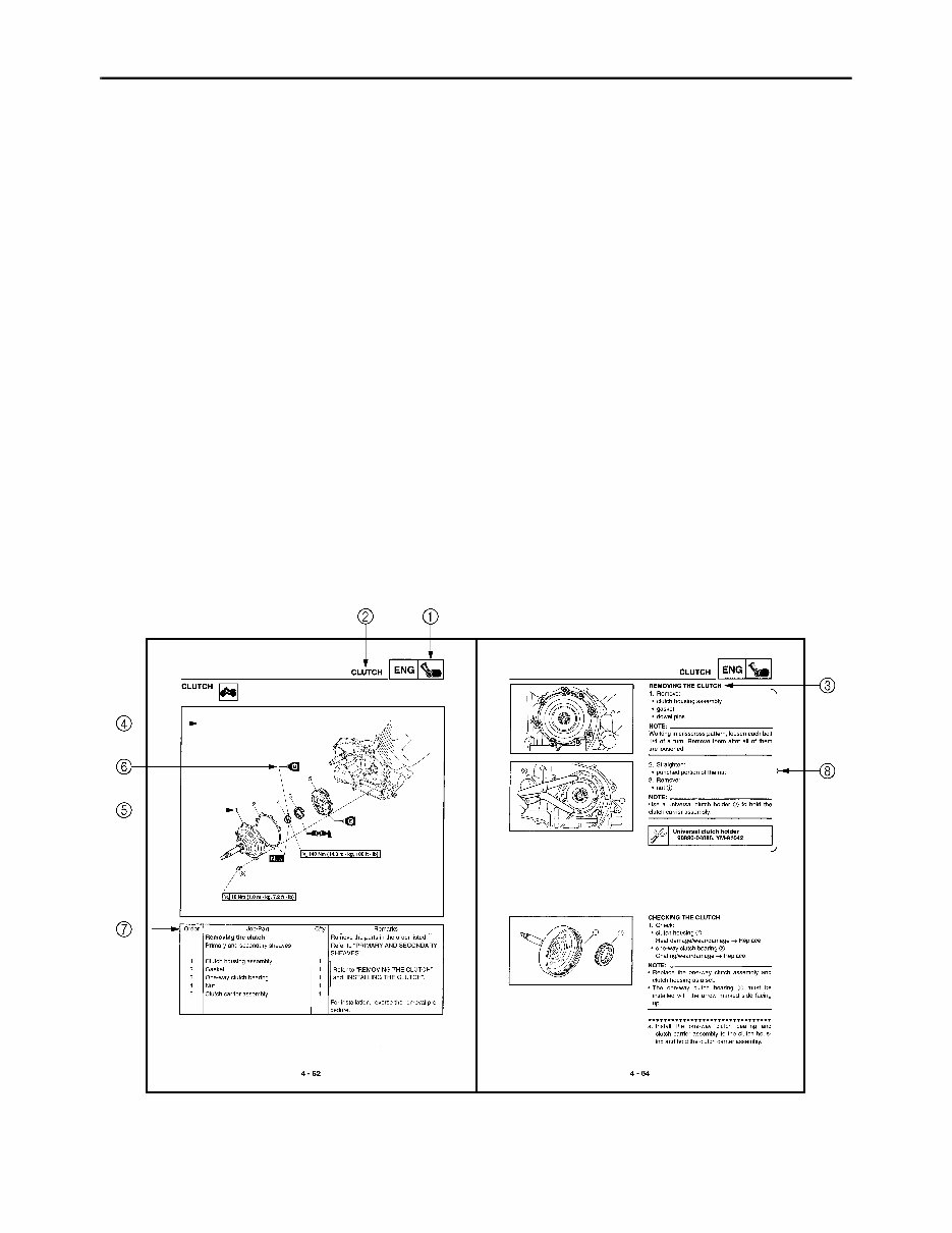
MANUAL ORGANIZATION
This manual consists of chapters for the main categories of subjects. (See “symbols”)
1st title 1: This is the title of the chapter with its symbol in the upper right corner of each page.
2nd title 2: This title indicates the section of the chapter and only appears on the first page of each
section. It is located in the upper left corner of the page.
3rd title 3: This title indicates a sub-section that is followed by step-by-step procedures accompa-
nied by corresponding illustrations.
EXPLODED DIAGRAMS
To help identify parts and clarify procedure steps, there are exploded diagrams at the start of each
removal and disassembly section.
1. An easy-to-see exploded diagram 4 is provided for removal and disassembly jobs.
2. Numbers 5 are given in the order of the jobs in the exploded diagram. A number that is enclosed
by a circle indicates a disassembly step.
3. An explanation of jobs and notes is presented in an easy-to-read way by the use of symbol marks
6. The meanings of the symbol marks are given on the next page.
4. A job instruction chart 7 accompanies the exploded diagram, providing the order of jobs, names
of parts, notes in jobs, etc.
5. For jobs requiring more information, the step-by-step format supplements 8 are given in addition
to the exploded diagram and the job instruction chart.
EBS00005
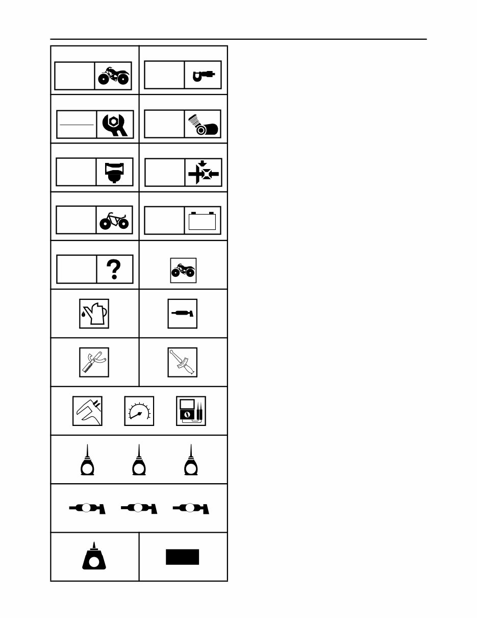
SYMBOLS
The following symbols are not relevant to
every vehicle.
Symbols 1 to 9 indicate the subject of each
chapter.
1 General information
2 Specifications
3 Periodic checks and adjustments
4 Engine
5 Carburetor
6 Drive train
7 Chassis
8 Electrical
9 Troubleshooting
Symbols 0 to G indicate the following.
0 Can be serviced with engine mounted
A Filling fluid
B Lubricant
C Special tool
D Torque
E Wear limit, clearance
F Engine speed
G Electrical data (Ω, V, A)
Symbols H to M in the exploded diagrams
indicate the types of lubricants and lubrication
points.
H Apply engine oil
I Apply gear oil
J Apply molybdenum disulfide oil
K Apply wheel bearing grease
L Apply lithium-soap-based grease
M Apply molybdenum disulfide grease
Symbols N to O in the exploded diagrams
indicate where to apply a locking agent N and
when to install a new part O.
N Apply the locking agent (LOCTITE
®
)
O Replace
1 2
3 4
5 6
7 8
9 0
A B
C D
E F G
H I J
K L M
N O
GEN
INFO
SPEC
CHK
ADJ
ENG
CARB DRIV
CHAS
– +
ELEC
TRBL
SHTG
T
R
.
.
E G M
B
LS M
LT
New

EBS00007
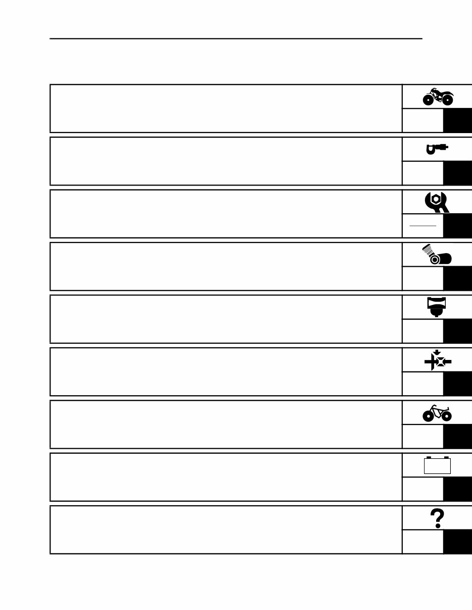
TABLE OF CONTENTS
GENERAL INFORMATION
GEN
INFO 1
SPECIFICATIONS
SPEC
2
PERIODIC CHECKS AND
ADJUSTMENTS
CHK
ADJ
3
ENGINE
ENG
4
CARBURETOR
CARB
5
DRIVE TRAIN
DRIV
6
CHASSIS
CHAS
7
ELECTRICAL
ELEC
8
TROUBLESHOOTING
TRBL
SHTG 9
– +

CONTENTS
CHAPTER 1
GENERAL INFORMATION
VEHICLE IDENTIFICATION............................................................................ 1-1
VEHICLE IDENTIFICATION NUMBER ..................................................... 1-1
MODEL LABEL.......................................................................................... 1-1
FEATURES ...................................................................................................... 1-2
WET MULTIPLE DISC BRAKE ................................................................. 1-2
IMPORTANT INFORMATION ......................................................................... 1-3
PREPARATION FOR REMOVAL AND DISASSEMBLY........................... 1-3
REPLACEMENT PARTS........................................................................... 1-3
GASKETS, OIL SEALS AND O-RINGS .................................................... 1-3
LOCK WASHERS/PLATES AND COTTER PINS ..................................... 1-4
BEARINGS AND OIL SEALS .................................................................... 1-4
CIRCLIPS .................................................................................................. 1-4
CHECKING THE CONNECTIONS ............................................................ 1-5
SPECIAL TOOLS ............................................................................................ 1-6
CHAPTER 2
SPECIFICATIONS
GENERAL SPECIFICATIONS ........................................................................ 2-1
ENGINE SPECIFICATIONS ............................................................................ 2-4
CHASSIS SPECIFICATIONS ........................................................................ 2-12
ELECTRICAL SPECIFICATIONS ................................................................. 2-14
TIGHTENING TORQUES .............................................................................. 2-16
ENGINE TIGHTENING TORQUES ......................................................... 2-16
CHASSIS TIGHTENING TORQUES ....................................................... 2-18
HOW TO USE THE CONVERSION TABLE.................................................. 2-20
GENERAL TIGHTENING TORQUE SPECIFICATIONS ............................... 2-20

LUBRICATION POINTS AND LUBRICANT TYPES .................................... 2-21
ENGINE ................................................................................................... 2-21
COOLANT FLOW DIAGRAMS ..................................................................... 2-22
CABLE ROUTING ......................................................................................... 2-23
CHAPTER 3
PERIODIC CHECKS AND ADJUSTMENTS
INTRODUCTION.............................................................................................. 3-1
PERIODIC MAINTENANCE CHART FOR THE EMISSION CONTROL
SYSTEM ......................................................................................................... 3-1
GENERAL MAINTENANCE AND LUBRICATION CHART ............................ 3-2
SEAT, CARRIERS, FENDERS AND FUEL TANK ......................................... 3-4
SEAT, FRONT CARRIER, FRONT GUARD AND FRONT FENDER ....... 3-4
REAR CARRIER AND REAR FENDER .................................................... 3-5
FUEL TANK ............................................................................................... 3-7
FOOTREST BOARDS ..................................................................................... 3-8
ENGINE ........................................................................................................... 3-9
ADJUSTING THE VALVE CLEARANCE .................................................. 3-9
ADJUSTING THE IDLING SPEED .......................................................... 3-11
ADJUSTING THE THROTTLE LEVER FREE PLAY .............................. 3-12
ADJUSTING THE SPEED LIMITER........................................................ 3-14
ADJUSTING THE STARTER CABLE ..................................................... 3-14
CHECKING THE SPARK PLUG ............................................................. 3-16
CHECKING THE IGNITION TIMING ....................................................... 3-17
MEASURING THE COMPRESSION PRESSURE .................................. 3-18
CHECKING THE ENGINE OIL LEVEL.................................................... 3-20
CHECKING THE OIL TEMPERATURE WARNING LIGHT .................... 3-22
CHANGING THE ENGINE OIL ............................................................... 3-22
CLEANING THE AIR FILTER.................................................................. 3-25
CHECKING THE CARBURETOR JOINT ................................................ 3-27
CHECKING THE FUEL HOSE ................................................................ 3-27
CHECKING THE CYLINDER HEAD BREATHER HOSE ....................... 3-28
CHECKING THE V-BELT ........................................................................ 3-28
CHECKING THE EXHAUST SYSTEM.................................................... 3-30
CLEANING THE SPARK ARRESTER .................................................... 3-30

CHASSIS ....................................................................................................... 3-32
ADJUSTING THE FRONT BRAKE ......................................................... 3-32
ADJUSTING THE REAR BRAKE ............................................................ 3-32
CHECKING THE FRONT BRAKE FLUID LEVEL ................................... 3-34
CHECKING THE FRONT BRAKE PADS ................................................ 3-34
CHECKING THE REAR BRAKE PLATES .............................................. 3-35
CHECKING THE BRAKE HOSES........................................................... 3-35
BLEEDING THE HYDRAULIC BRAKE SYSTEM ................................... 3-36
ADJUSTING THE SELECT LEVER CONTROL CABLE AND SHIFT
ROD........................................................................................................ 3-38
ADJUSTING THE REAR BRAKE LIGHT SWITCH ................................. 3-39
CHECKING THE FINAL GEAR OIL LEVEL ............................................ 3-40
CHANGING THE FINAL GEAR OIL ........................................................ 3-41
CHECKING THE DIFFERENTIAL GEAR OIL ......................................... 3-42
CHANGING THE DIFFERENTIAL GEAR OIL ........................................ 3-42
CHECKING THE CONSTANT VELOCITY JOINT DUST BOOTS .......... 3-43
CHECKING THE STEERING SYSTEM .................................................. 3-43
ADJUSTING THE TOE-IN ....................................................................... 3-44
ADJUSTING THE FRONT SHOCK ABSORBERS ................................. 3-45
ADJUSTING THE REAR SHOCK ABSORBERS .................................... 3-46
CHECKING THE TIRES .......................................................................... 3-47
CHECKING THE WHEELS ..................................................................... 3-49
CHECKING AND LUBRICATING THE CABLES .................................... 3-49
LUBRICATING THE LEVERS AND PEDALS ......................................... 3-50
ELECTRICAL SYSTEM................................................................................. 3-51
CHECKING AND CHARGING THE BATTERY ....................................... 3-51
CHECKING THE FUSES ........................................................................ 3-57
ADJUSTING THE HEADLIGHT BEAMS ................................................. 3-59
CHANGING A HEADLIGHT BULB .......................................................... 3-59
CHAPTER 4
ENGINE
ENGINE REMOVAL ........................................................................................ 4-1
AIR DUCTS, MUFFLER AND EXHAUST PIPE ........................................ 4-1
SELECT LEVER UNIT .............................................................................. 4-3
LEADS, CABLES AND HOSES ................................................................ 4-4
ENGINE MOUNTING BOLTS ................................................................... 4-5
INSTALLING THE ENGINE....................................................................... 4-7
INSTALLING THE MUFFLER AND EXHAUST PIPE................................ 4-8
OIL COOLER................................................................................................... 4-9
You're Reading a Preview
What's Included?
 Lifetime Access
Fast Download Speeds
Online & Offline Access
Access PDF Contents & Bookmarks
Full Search Facility
Print one or all pages of your manual
$39.99
Yamaha Grizzly 350 IRS 4WD Hunter ATV 2007-2011 Full Service & Repair Manual
Viewed 27 Times Today

What's Included?
Lifetime Access
Fast Download Speeds
Online & Offline Access
Access PDF Contents & Bookmarks
Full Search Facility
Print one or all pages of your manual
$39.99

Secure transaction
What's Included?
Lifetime Access
Fast Download Speeds
Online & Offline Access
Access PDF Contents & Bookmarks
Full Search Facility
Print one or all pages of your manual
Description
- This full service and repair manual is a comprehensive factory workshop manual for the Yamaha Grizzly 350 IRS 4WD Hunter ATV, covering the years 2007-2011.
- It is a professional manual that encompasses all repair, servicing, and troubleshooting procedures with detailed photos and diagrams.
- Professional mechanics and technicians use this type of manual, which includes step-by-step instructions and highly detailed exploded diagrams and pictures for accurate completion of every job.
- You have the option to print out a single page or the entire manual as per your requirement.
- This manual can be used on multiple computers without any limitations or trial periods and does not expire.
- It is fully compatible with Windows and MAC computers.
For instant access to this manual, please click on the button below.


