EB001000 NOTICE This manual was produced by the Yamaha Motor Company primarily for use by Yamaha dealers and their qualified mechanics. It is not possible to include all the knowledge of a mechanic in one manual, so it is assumed that anyone who uses this book to perform maintenance and repairs on Yamaha machine has a basic understanding of the mechanical ideas and the procedures of machine repair. Repairs attempted by anyone without this knowledge are likely to render the machine unsafe and unfit for use. Yamaha Motor Company, Ltd. is continually striving to improve all its models. Modifications and significant changes in specifications or procedures will be forwarded to all authorized Yamaha dealers and will appear in future editions of this manual where applicable. NOTE: Designs and specifications are subject to change without notice. IMPORTANT INFORMATION Particularly important information is distinguished in this manual by the following notations. The Safety Alert Symbol means ATTENTION! BECOME ALERT! YOUR SAFETY IS INVOLVED! Failure to follow WARNING instructions could result in severe injury or death to the machine operator, a bystander or a person inspecting or repairing the machine. A CAUTION indicates special precautions that must be taken to avoid damage to the machine. A NOTE provides key information to make procedures easier or clearer. WARNING CAUTION: NOTE:
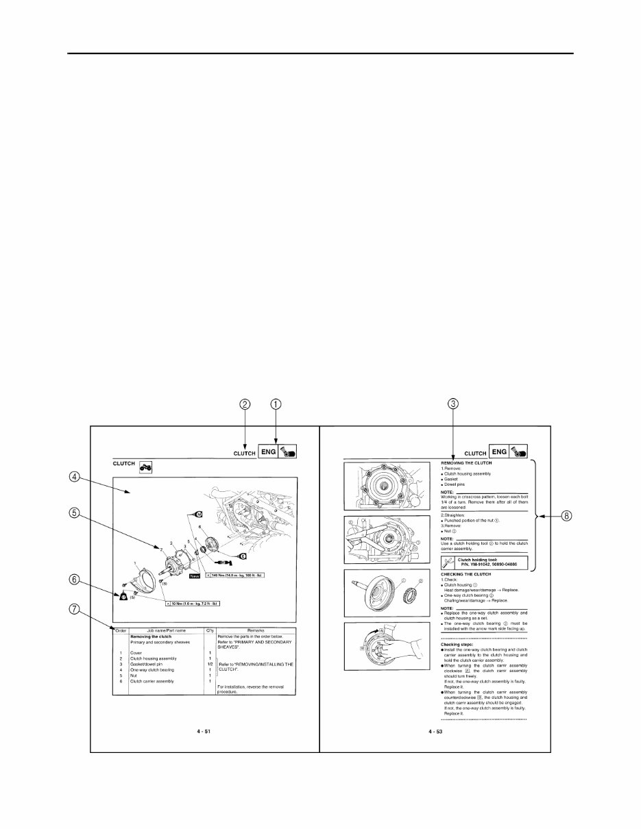
EB002000 HOW TO USE THIS MANUAL MANUAL ORGANIZATION This manual consists of chapters for the main categories of subjects. (See “Illustrated symbols”) 1st title 1: This is the title of the chapter with its symbol in the upper right corner of each page. 2nd title 2: This title indicates the section of the chapter and only appears on the first page of each section. It is located in the upper left corner of the page. 3rd title 3: This title indicates a sub-section that is followed by step-by-step procedures accompanied by corresponding illustrations. EXPLODED DIAGRAMS To help identify parts and clarify procedure steps, there are exploded diagrams at the start of each removal and disassembly section. 1. An easy-to-see exploded diagram 4 is provided for removal and disassembly jobs. 2. Numbers 5 are given in the order of the jobs in the exploded diagram. A number that is enclosed by a circle indicates a disassembly step. 3. An explanation of jobs and notes is presented in an easy-to-read way by the use of symbol marks 6. The meanings of the symbol marks are given on the next page. 4. A job instruction chart 7 accompanies the exploded diagram, providing the order of jobs, names of parts, notes in jobs, etc. 5. For jobs requiring more information, the step-by-step format supplements 8 are given in addition to the exploded diagram and the job instruction chart.
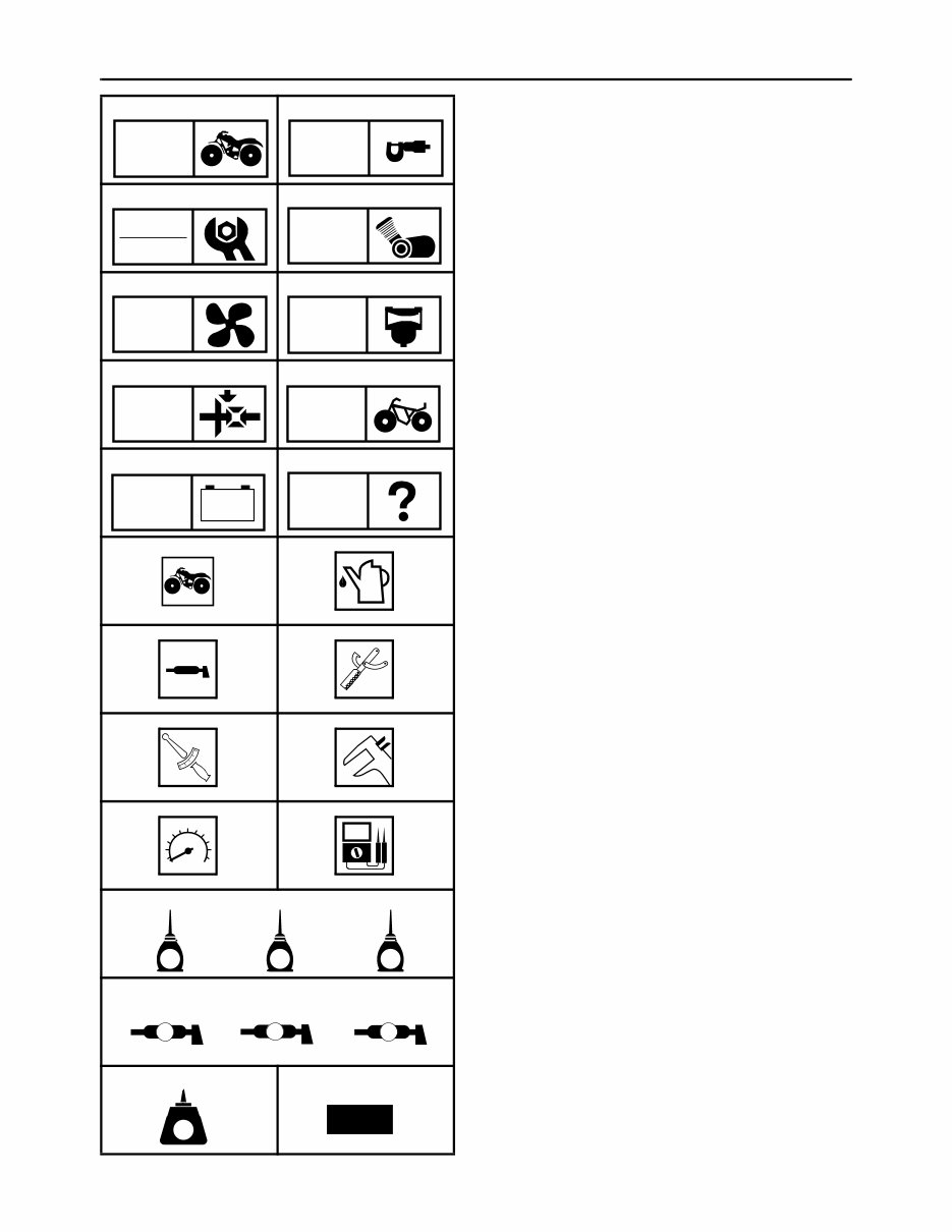
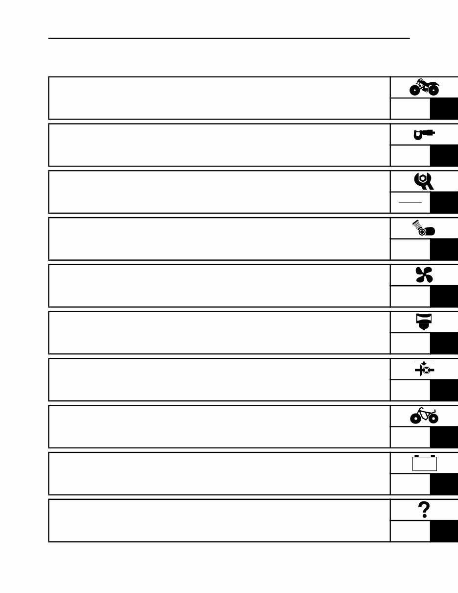
EB003000 ILLUSTRATED SYMBOLS Illustrated symbols 1 to 0 are printed on the top right of each page and indicate the subject of each chapter. 1 General information 2 Specifications 3 Periodic checks and adjustments 4 Engine 5 Cooling system 6 Carburetion 7 Drive train 8 Chassis 9 Electrical 0 Troubleshooting Illustrated symbols A to H are used to identify the specifications appearing in the text. A Can be serviced with engine mounted B Filling fluid C Lubricant D Special tool E Torque F Wear limit, clearance G Engine speed H Ω, V, A Illustrated symbols I to N in the exploded diagrams indicate the types of lubricants and lubrication points. I Apply engine oil J Apply gear oil K Apply molybdenum disulfide oil L Apply wheel bearing grease M Apply lithium-soap-based grease N Apply molybdenum disulfide grease Illustrated symbols O to P in the exploded diagrams indicate where to apply a locking agent O and when to install a new part P. O Apply the locking agent (LOCTITE ® ) P Replace 1 2 3 4 5 6 7 8 9 0 A B C D E F G H I J K L M N O P GEN INFO SPEC CHK ADJ ENG COOL CARB DRIV CHAS – + ELEC TRBL SHTG T R . . E G M B LS M LT New
TABLE OF CONTENTS GENERAL INFORMATION GEN INFO 1 SPECIFICATIONS SPEC 2 PERIODIC CHECKS AND ADJUSTMENTS CHK ADJ 3 ENGINE ENG 4 COOLING SYSTEM COOL 5 CARBURETION CARB 6 DRIVE TRAIN DRIV 7 CHASSIS CHAS 8 ELECTRICAL ELEC 9 TROUBLESHOOTING TRBL SHTG 10 – +
CONTENTS CHAPTER 1. GENERAL INFORMATION MACHINE IDENTIFICATION ........................................................................ 1-1 VEHICLE IDENTIFICATION NUMBER ................................................. 1-1 MODEL LABEL ...................................................................................... 1-1 FEATURES ................................................................................................... 1-2 LIQUID COOLING ENGINE .................................................................. 1-2 PARK POSITION ................................................................................... 1-2 FRONT DIFFERENTIAL ........................................................................ 1-3 IMPORTANT INFORMATION ....................................................................... 1-8 PREPARATION FOR REMOVAL PROCEDURES ............................... 1-8 REPLACEMENT PARTS ....................................................................... 1-8 GASKETS, OIL SEALS AND O-RINGS ................................................ 1-8 LOCK WASHERS/PLATES AND COTTER PINS ................................. 1-9 BEARINGS AND OIL SEALS ................................................................ 1-9 CIRCLIPS .............................................................................................. 1-9 CHECKING OF CONNECTIONS ................................................................ 1-10 SPECIAL TOOLS ........................................................................................ 1-11 CHAPTER 2. SPECIFICATIONS GENERAL SPECIFICATIONS ...................................................................... 2-1 MAINTENANCE SPECIFICATIONS ............................................................. 2-4 ENGINE ................................................................................................. 2-4 CHASSIS ............................................................................................. 2-14 ELECTRICAL ...................................................................................... 2-18 HOW TO USE THE CONVERSION TABLE ............................................... 2-20 GENERAL TORQUE SPECIFICATIONS ................................................... 2-20 LUBRICATION POINTS AND LUBRICANT TYPES .................................. 2-21 ENGINE ............................................................................................... 2-21
COOLANT FLOW DIAGRAMS ................................................................... 2-22 OIL FLOW DIAGRAMS .............................................................................. 2-24 CABLE ROUTING ....................................................................................... 2-27 CHAPTER 3. PERIODIC CHECKS AND ADJUSTMENTS INTRODUCTION ........................................................................................... 3-1 PERIODIC MAINTENANCE/LUBRICATION ................................................ 3-1 SEAT, CARRIERS, FENDERS AND FUEL TANK ....................................... 3-3 SEAT AND SIDE PANELS .................................................................... 3-3 FRONT CARRIER, FRONT BUMPER AND FRONT FENDER ............. 3-4 REAR CARRIER AND REAR FENDER ................................................ 3-6 FUEL TANK ........................................................................................... 3-8 FOOTREST BOARDS .................................................................................. 3-9 ENGINE ....................................................................................................... 3-10 ADJUSTING THE VALVE CLEARANCE ............................................ 3-10 ADJUSTING THE IDLING SPEED ...................................................... 3-13 ADJUSTING THE THROTTLE LEVER FREE PLAY .......................... 3-14 ADJUSTING THE SPEED LIMITER .................................................... 3-16 ADJUSTING THE STARTER CABLE ................................................. 3-17 CHECKING THE SPARK PLUG ......................................................... 3-19 CHECKING THE IGNITION TIMING ................................................... 3-20 MEASURING THE COMPRESSION PRESSURE .............................. 3-21 CHECKING THE ENGINE OIL LEVEL ................................................ 3-23 CHANGING THE ENGINE OIL ........................................................... 3-24 CLEANING THE AIR FILTER .............................................................. 3-26 CHECKING THE COOLANT LEVEL ................................................... 3-29 CHANGING THE COOLANT ............................................................... 3-30 COOLANT TEMPERATURE WARNING LIGHT CHECK ................... 3-33 CHECKING THE V-BELT .................................................................... 3-33 CLEANING THE SPARK ARRESTER ................................................ 3-34
CHASSIS .................................................................................................... 3-36 ADJUSTING THE REAR BRAKE ........................................................ 3-36 CHECKING THE BRAKE FLUID LEVEL ............................................. 3-38 CHECKING THE FRONT BRAKE PAD .............................................. 3-39 CHECKING THE REAR BRAKE PAD ................................................. 3-39 CHECKING THE BRAKE HOSE ......................................................... 3-40 BLEEDING THE HYDRAULIC BRAKE SYSTEM ............................... 3-41 ADJUSTING THE SELECT LEVER CONTROL CABLE AND SHIFT ROD ............................................................................. 3-42 ADJUSTING THE REAR BRAKE LIGHT SWITCH ............................. 3-43 CHECKING THE FINAL GEAR OIL LEVEL ........................................ 3-44 CHANGING THE FINAL GEAR OIL .................................................... 3-45 CHECKING THE DIFFERENTIAL GEAR OIL ..................................... 3-46 CHANGING THE DIFFERENTIAL GEAR OIL .................................... 3-46 CHECKING THE CONSTANT VELOCITY JOINT DUST BOOT ........ 3-47 CHECKING THE STEERING SYSTEM .............................................. 3-48 ADJUSTING THE TOE-IN ................................................................... 3-48 ADJUSTING THE FRONT SHOCK ABSORBER ................................ 3-50 ADJUSTING THE REAR SHOCK ABSORBER .................................. 3-50 CHECKING THE TIRE ........................................................................ 3-50 CHECKING THE WHEEL .................................................................... 3-53 CHECKING AND LUBRICATING THE CABLE ................................... 3-53 LUBRICATING THE LEVERS, PEDAL, ETC. ..................................... 3-54 ELECTRICAL .............................................................................................. 3-55 CHECKING THE BATTERY ................................................................ 3-55 CHECKING THE FUSE ....................................................................... 3-60 ADJUSTING THE HEADLIGHT BEAM ............................................... 3-62 CHANGING THE HEADLIGHT BULB ................................................. 3-62 CHAPTER 4. ENGINE ENGINE REMOVAL ...................................................................................... 4-1 AIR DUCTS, MUFFLER AND EXHAUST PIPE .................................... 4-1 SELECT LEVER UNIT AND COOLANT RESERVOIR ......................... 4-3 HOSES AND LEADS ............................................................................. 4-4 ENGINE MOUNTING BOLTS ............................................................... 4-5 INSTALLING THE ENGINE ................................................................... 4-7 CYLINDER HEAD ......................................................................................... 4-8 REMOVING THE CYLINDER HEAD ................................................... 4-10 CHECKING THE TAPPET COVER ..................................................... 4-11 CHECKING THE TIMING CHAIN TENSIONER .................................. 4-11 CHECKING THE CAMSHAFT SPROCKET ........................................ 4-11 CHECKING THE CYLINDER HEAD ................................................... 4-12 INSTALLING THE CYLINDER HEAD ................................................. 4-13
CAMSHAFT, ROCKER ARMS AND VALVES ........................................... 4-16 REMOVING THE CAMSHAFT AND ROCKER ARM .......................... 4-18 REMOVING THE VALVE AND VALVE SPRING ................................ 4-18 CHECKING THE CAMSHAFT ............................................................. 4-19 CHECKING THE ROCKER ARM AND CAMSHAFT ........................... 4-19 CHECKING THE VALVE AND VALVE SPRING ................................. 4-21 INSTALLING THE VALVE AND VALVE SPRING ............................... 4-25 INSTALLING THE CAMSHAFT AND ROCKER ARM ......................... 4-26 CYLINDER AND PISTON ........................................................................... 4-27 REMOVING THE PISTON .................................................................. 4-28 CHECKING THE TIMING CHAIN GUIDE ........................................... 4-28 CHECKING THE CYLINDER AND PISTON ....................................... 4-28 CHECKING THE PISTON RING ......................................................... 4-30 CHECKING THE PISTON PIN ............................................................ 4-31 INSTALLING THE PISTON ................................................................. 4-32 INSTALLING THE CYLINDER ............................................................ 4-33 RECOIL STARTER AND A.C. MAGNETO ................................................ 4-34 REMOVING THE A.C. MAGNETO ...................................................... 4-37 DISASSEMBLING THE RECOIL STARTER ....................................... 4-37 CHECKING THE CDI MAGNETO ....................................................... 4-37 CHECKING THE STARTER CLUTCH ................................................ 4-38 CHECKING THE STARTER PULLEY ................................................. 4-39 CHECKING THE RECOIL STARTER ................................................. 4-39 ASSEMBLING THE RECOIL STARTER ............................................. 4-39 INSTALLING THE A.C. MAGNETO .................................................... 4-40 PRIMARY AND SECONDARY SHEAVES ................................................. 4-42 PRIMARY SLIDING SHEAVE ............................................................. 4-44 SECONDARY SHEAVE ...................................................................... 4-45 REMOVING THE PRIMARY AND SECONDARY SHEAVES ............. 4-46 DISASSEMBLING THE SECONDARY SHEAVE ................................ 4-46 CHECKING THE PRIMARY SHEAVE ................................................ 4-47 CHECKING THE SECONDARY SHEAVE .......................................... 4-47 ASSEMBLING THE PRIMARY SHEAVE ............................................ 4-48 ASSEMBLING THE SECONDARY SHEAVE ...................................... 4-48 INSTALLING THE PRIMARY AND SECONDARY SHEAVES ............ 4-50 CLUTCH ...................................................................................................... 4-51 REMOVING THE CLUTCH ................................................................. 4-53 CHECKING THE CLUTCH .................................................................. 4-53 INSTALLING THE CLUTCH ................................................................ 4-54
Get your hands on the 2007-2010 Yamaha Kodiak 450 ATV (YFM450FAR) Service & Repair Manual for comprehensive troubleshooting and replacement procedures. This manual is a valuable resource for both professional mechanics and DIY enthusiasts, featuring step-by-step instructions, clear images, and exploded-view illustrations.
Regular maintenance is essential for the durability of your ATV. Over time, certain parts will wear out and require replacement. With this repair manual, you'll have access to the manufacturer's recommended troubleshooting charts and procedures, enabling you to save on repairs and enhance your ATV's reliability.
Say goodbye to flipping through numerous pages or dealing with greasy, torn, or lost pages. This .pdf format manual allows for easy navigation, searching, and bookmarking. It's also printable if you prefer a physical copy. The manual is compatible with various electronic devices, including PC, Mac, Android, and Apple devices, and only requires Adobe Reader (free) for access.
Recently Viewed
5,521,897Happy Clients
2,594,462eManuals
1,120,453Trusted Sellers
15Years in Business
Price:
Actual Price:
2007-2010 Yamaha Kodiak 450 ATV (YFM450FAR) Service & Repair Manual