How to use this Service Manual In the bookmarks to the left you will find different segments of this manual: Service Manual This is the standard manual for this vehicle. Use this segment as your major point of reference and information. Supplementary Service Manual (if available) These segments are updates and additions to the standard service manual. They are added as needed when certain changes are made to the model. Be sure to check these for additional information that may be lacking from the regular service manual.
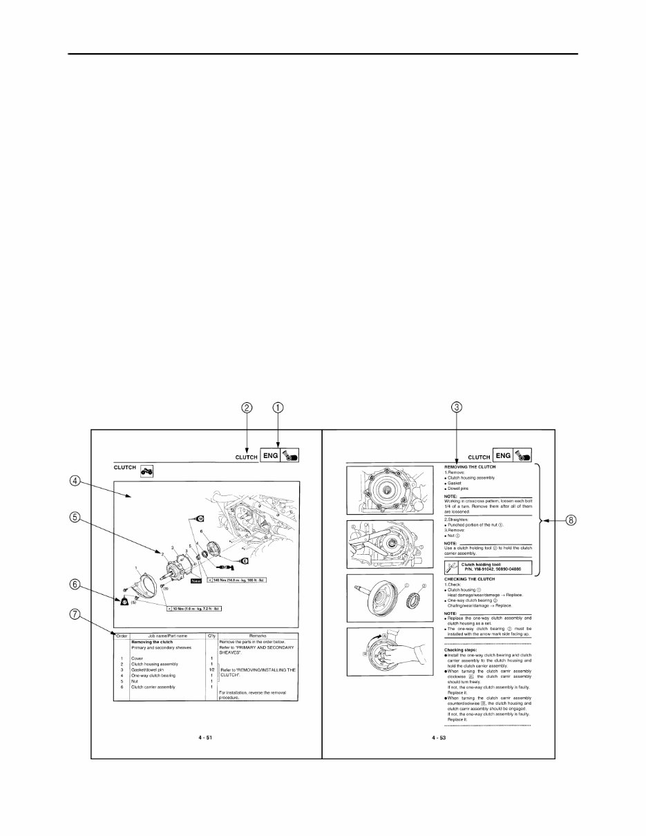
EB002000 HOW TO USE THIS MANUAL MANUAL ORGANIZATION This manual consists of chapters for the main categories of subjects. (See “Illustrated symbols”) 1st title 1: This is the title of the chapter with its symbol in the upper right corner of each page. 2nd title 2: This title indicates the section of the chapter and only appears on the first page of each section. It is located in the upper left corner of the page. 3rd title 3: This title indicates a sub-section that is followed by step-by-step procedures accompanied by corresponding illustrations. EXPLODED DIAGRAMS To help identify parts and clarify procedure steps, there are exploded diagrams at the start of each removal and disassembly section. 1. An easy-to-see exploded diagram 4 is provided for removal and disassembly jobs. 2. Numbers 5 are given in the order of the jobs in the exploded diagram. A number that is enclosed by a circle indicates a disassembly step. 3. An explanation of jobs and notes is presented in an easy-to-read way by the use of symbol marks 6. The meanings of the symbol marks are given on the next page. 4. A job instruction chart 7 accompanies the exploded diagram, providing the order of jobs, names of parts, notes in jobs, etc. 5. For jobs requiring more information, the step-by-step format supplements 8 are given in addition to the exploded diagram and the job instruction chart.
EB003000 ILLUSTRATED SYMBOLS Illustrated symbols 1 to 0 are printed on the top right of each page and indicate the subject of each chapter. 1 General information 2 Specifications 3 Periodic checks and adjustments 4 Engine 5 Cooling system 6 Carburetion 7 Drive train 8 Chassis 9 Electrical 0 Troubleshooting Illustrated symbols A to H are used to identify the specifications appearing in the text. A Can be serviced with engine mounted B Filling fluid C Lubricant D Special tool E Torque F Wear limit, clearance G Engine speed H Ω, V, A Illustrated symbols I to N in the exploded diagrams indicate the types of lubricants and lubrication points. I Apply engine oil J Apply gear oil K Apply molybdenum disulfide oil L Apply wheel bearing grease M Apply lithium-soap-based grease N Apply molybdenum disulfide grease Illustrated symbols O to P in the exploded diagrams indicate where to apply a locking agent O and when to install a new part P. O Apply the locking agent (LOCTITE ® ) P Replace 1 2 3 4 5 6 7 8 9 0 A B C D E F G H I J K L M N O P GEN INFO SPEC CHK ADJ ENG COOL CARB DRIV CHAS – + ELEC TRBL SHTG T R . . E G M B LS M LT New
CONTENTS GENERAL INFORMATION SPECIAL TOOLS ..................................................................................... 1 SPECIFICATIONS GENERAL SPECIFICATIONS ................................................................. 2 MAINTENANCE SPECIFICATIONS ........................................................ 5 ENGINE ................................................................................................ 5 CHASSIS ............................................................................................ 15 ELECTRICAL ..................................................................................... 19 LUBRICATION POINTS AND LUBRICANT TYPES .............................. 21 ENGINE .............................................................................................. 21 OIL FLOW DIAGRAMS .......................................................................... 22 CABLE ROUTING .................................................................................. 26 PERIODIC CHECKS AND ADJUSTMENTS INTRODUCTION .................................................................................... 34 PERIODIC MAINTENANCE/LUBRICATION .......................................... 34 SEAT, CARRIERS, FENDERS AND FUEL TANK ................................. 36 SEAT, FRONT CARRIER, FRONT BUMPER AND FRONT FENDER ............................................................................... 36 FUEL TANK ........................................................................................ 38 ENGINE .................................................................................................. 39 CHECKING THE OIL TEMPERATURE WARNING LIGHT ............... 39 ENGINE CYLINDER HEAD .................................................................................. 40 CAMSHAFT, ROCKER ARMS AND VALVES ....................................... 42 CYLINDER AND PISTON ...................................................................... 44 RECOIL STARTER AND A.C. MAGNETO ............................................ 45 BALANCER GEARS AND OIL PUMP .................................................... 47 OIL PUMP .......................................................................................... 49 REMOVING THE BALANCER DRIVE GEAR AND BALANCER DRIVEN GEAR .............................................................. 50 REMOVING THE BALANCER DRIVE GEAR AND BUFFER BOSS .................................................................................. 50 CHECKING THE OIL PUMP DRIVEN GEAR .................................... 50 CHECKING THE BALANCER DRIVE GEAR AND BALANCER DRIVEN GEAR .............................................................. 50 INSTALLING THE BALANCER DRIVE GEAR AND BALANCER DRIVEN GEAR .............................................................. 51 OIL COOLER .......................................................................................... 52
PRIMARY AND SECONDARY SHEAVES ............................................. 54 PRIMARY SLIDING SHEAVE ............................................................ 56 SECONDARY SHEAVE ..................................................................... 57 ASSEMBLING THE PRIMARY SHEAVE ........................................... 58 ASSEMBLING THE SECONDARY SHEAVE .................................... 58 CLUTCH ................................................................................................. 60 CRANKCASE ......................................................................................... 62 STARTER MOTOR, TIMING CHAIN AND OIL FILTER ..................... 62 CRANKCASE ..................................................................................... 64 CRANKCASE BEARINGS ................................................................. 65 SEPARATING THE CRANKCASE ..................................................... 66 ASSEMBLING THE CRANKCASE .................................................... 66 CRANKSHAFT ....................................................................................... 68 REMOVING THE CRANKSHAFT ...................................................... 69 INSTALLING THE CRANKSHAFT ..................................................... 69 TRANSMISSION .................................................................................... 70 INSTALLING THE TRANSMISSION .................................................. 71 MIDDLE GEAR ....................................................................................... 72 MIDDLE DRIVE SHAFT ..................................................................... 72 MIDDLE DRIVEN SHAFT .................................................................. 73 SELECTING THE MIDDLE DRIVE AND DRIVEN GEAR SHIMS ..... 75 DRIVE TRAIN FRONT CONSTANT VELOCITY JOINTS AND DIFFERENTIAL GEAR ........................................................................... 79 MEASURING AND ADJUSTING THE DIFFERENTIAL GEAR LASH ....................................................................................... 81 CHASSIS REAR BRAKE ........................................................................................ 83 CHECKING THE REAR BRAKE ........................................................ 85 INSTALLING THE REAR BRAKE ...................................................... 86 STEERING SYSTEM ............................................................................. 89 STEERING STEM .............................................................................. 89 FRONT ARMS AND FRONT SHOCK ABSORBERS ............................. 91 ELECTRICAL ELECTRIC STARTING SYSTEM ........................................................... 93 STARTER MOTOR ............................................................................ 93 ASSEMBLING THE STARTER MOTOR ............................................ 94 SIGNAL SYSTEM ................................................................................... 95 CIRCUIT DIAGRAM ........................................................................... 95 COOLING SYSTEM ............................................................................... 99 CIRCUIT DIAGRAM ........................................................................... 99 TROUBLESHOOTING .................................................................... 100
TROUBLESHOOTING FAULTY GEAR SHIFTING ................................................................... 104 HARD SHIFTING ............................................................................. 104 SHIFT LEVER DOES NOT MOVE ................................................... 104 JUMPS OUT OF GEAR ................................................................... 104 OVERHEATING ................................................................................... 104 OVERHEATING ............................................................................... 104 FAULTY BRAKE ................................................................................... 105 POOR BRAKING EFFECT ............................................................... 105 YFM350FAS WIRING DIAGRAM
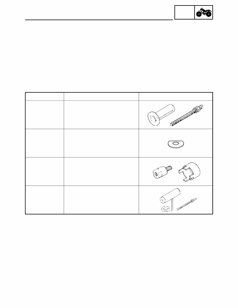
GEN INFO – 1 – SPECIAL TOOLS GENERAL INFORMATION EB102001 SPECIAL TOOLS The following special tools are necessary for complete and accurate tune-up and assembly. Use only the appropriate special tools; this will help prevent damage caused by the use of inappropriate tools or improvised techniques. Special tools may differ by shape and part number from country to country. In such a case, two types are provided. When placing an order, refer to the list provided below to avoid any mistakes. For US and CDN P/N. YM-, YU-, YS-, YK-, ACC- Except for US and CDN P/N. 90890- Tool No. Tool name/How to use Illustration Pot 90890-01274 Bolt 90890-01275 Crankshaft installer pot Crankshaft installer bolt These tools are used to install the crankshaft. 90890-01309 Spacer This tool is used to install the crankshaft. Adapter 90890-01383 YM-1383 Spacer 90890-04081 YM-91044 Adapter Spacer (crankshaft installer) These tools are used to install the crankshaft. YU-90050 Crankshaft installer set These tools are used to install the crankshaft.
– 2 – SPEC SPECIFICATIONS GENERAL SPECIFICATIONS Item Standard Model code: 5UH1 Dimensions: Overall length 1,984 mm (78.1 in) Overall width 1,085 mm (42.7 in) Overall height 1,120 mm (44.1 in) Seat height 827 mm (32.6 in) Wheelbase 1,233 mm (48.5 in) Minimum ground clearance 245 mm (9.7 in) Minimum turning radius 3,000 mm (118.1 in) Basic weight: With oil and full fuel tank 258 kg (569 lb) Engine: Engine type Air-cooled 4-stroke, SOHC Cylinder arrangement Forward-inclined single cylinder Displacement 348 cm 3 Bore × stroke 83.0 × 64.5 mm (3.27 × 2.54 in) Compression ratio 9.2 : 1 Standard compression pressure (at sea level) 1,050 kPa (10.5 kg/cm 2 , 149.3 psi) at 750 r/min Starting system Electric and recoil starter Lubrication system: Wet sump Oil type or grade: Engine oil API service SE, SF, SG type or higher Final gear oil SAE 80API “GL-4” Hypoid Gear Oil Differential gear oil SAE 80API “GL-4” Hypoid Gear Oil Oil capacity: Engine oil Periodic oil change 2.2 L (1.94 Imp qt, 2.33 US qt) With oil filter replacement 2.3 L (2.02 Imp qt, 2.43 US qt) Total amount 3.1 L (2.73 Imp qt, 3.28 US qt) Final gear case oil Periodic oil change 0.23 L (0.20 Imp qt, 0.24 US qt) Total amount 0.25 L (0.22 Imp qt, 0.26 US qt) 0° 10° 30° 50° 70° 90° 110° -20° -10° 0° 10° 20° 30° 40° 130°F 50°C YAMALUBE 4 (20W40) or SAE 20W40 YAMALUBE 4 (10W30) or SAE 10W30 SAE 5W30 GENERAL SPECIFICATIONS
– 3 – SPEC Differential gear case oil Periodic oil change 0.35 L (0.31 Imp qt, 0.37 US qt) Total amount 0.40 L (0.35 Imp qt, 0.42 US qt) Air filter: Wet type element Fuel: Type Unleaded gasoline only Fuel tank capacity 13.5 L (2.97 Imp gal, 3.57 US gal) Fuel reserve amount 3.3 L (0.73 Imp gal, 0.87 US gal) Carburetor: Type/quantity BSR33/1 Manufacturer MIKUNI Spark plug: Type/manufacturer DR8EA/NGK Spark plug gap 0.6 ~ 0.7 mm (0.024 ~ 0.028 in) Clutch type: Wet, centrifugal automatic Transmission: Primary reduction system V-belt Secondary reduction system Shaft drive Secondary reduction ratio 41/21 × 24/18 × 33/9 (9.545) Transmission type V-belt automatic Operation Left hand operation Single speed automatic 2.60 ~ 0.75 : 1 Sub transmission ratio 35/20 (1.750) Reverse gear 26/15 (1.733) Chassis: Frame type Steel tube frame Caster angle 4° Camber angle 1° Kingpin angle 11° Kingpin offset –5.0 mm (–0.20 in) Trail 21 mm (0.83 in) Tread (STD) front 850 mm (33.46 in) rear 825 mm (32.48 in) Toe-in 0 ~ 10 mm (0 ~ 0.39 in) Tires: Type Tubeless Size front AT25 × 8–12 rear AT25 × 10–12 Manufacturer front MAXXIS rear MAXXIS Type front M911Y rear M912Y Item Standard GENERAL SPECIFICATIONS
– 4 – SPEC Tire pressure (cold tire): Maximum load* 210 kg (463 lb) Off-road riding front 22 ~ 28 kPa (0.22 ~ 0.28 kg/cm 2 , 3.2 ~ 4.0 psi) rear 22 ~ 28 kPa (0.22 ~ 0.28 kg/cm 2 , 3.2 ~ 4.0 psi) *Load in total weight of rider accessories Brakes: Front brake type Dual disc brake operation Right hand operation Rear brake type Drum brake operation Left hand and right foot operation Suspension: Front suspension Double wishbone Rear suspension Swingarm (monocross) Shock absorbers: Front shock absorber Coil spring/oil damper Rear shock absorber Coil spring/oil damper Wheel travel: Front wheel travel 160 mm (6.30 in) Rear wheel travel 180 mm (7.09 in) Electrical: Ignition system D.C. C.D.I. Generator system A.C. magneto Battery type YTX14AH Battery capacity 12 V 12 Ah Headlight type: Krypton bulb Bulb wattage × quantity: Headlight 12 V 30 W/30 W × 2 Tail/brake light 12 V 5 W/21 W × 1 Indicator lights Neutral 12 V 1.7 W × 1 Reverse 12 V 1.7 W × 1 Oil temperature 12 V 1.7 W × 1 Four-wheel drive 14 V 1.7 W × 1 Item Standard GENERAL SPECIFICATIONS
This Service Repair Workshop Manual provides a comprehensive and easily navigable layout, offering detailed repair procedures. It is designed to enhance your understanding of your vehicle's parts and repair processes, enabling you to perform your own servicing and repairs with confidence.
All models for the specified years and engine types are covered in this manual. It is specifically tailored to the mentioned model, similar to the manuals utilized by local Dealers/Mechanics.
The manual encompasses a wide range of information, including but not limited to routine maintenance, tune-up procedures, specifications, engine removal/installation, cylinder head/valve train, engine block, engine lubrication, intake manifold/exhaust system, cooling and heating, fuel and emissions, transaxle, clutch, manual transmission, automatic transmission, differential, driveshaft, steering, suspension, brakes (including ABS), body, heater and air conditioning, automatic climate control, electrical (including SRS), supplemental restraint system (SRS), engine repair, air conditioning, exhaust, emissions control, ignition, steering, wiring diagrams, valve timing procedures, chain & gear replacement, general removal & installation instructions, safety precautions, special tools, tensioner adjustments, tightening torques, timing marks, valve timing instructions, tensioner release & reset methods, chain routing & sprocket/gear valve timing marks, etc.
Upon payment with your Credit/Debit/Paypal Account, instant delivery of this manual is guaranteed. There is no shipping involved, ensuring immediate access to the manual for prompt utilization.
By utilizing this manual, you can potentially save thousands of dollars. It empowers you to undertake tasks that might otherwise incur substantial costs when handled by mechanics, offering significant cost savings.
This manual is user-friendly and easily accessible. It is in PDF format, compatible with any PC/MAC computer using Microsoft Windows, including XP, NT, 2000, Vista, Windows 7, and more. Its simplicity makes it as easy to use as opening an email.