
,YFMA1W Service Manual")
2002 Yamaha ATV YFA1(P),YFMA1W Service Manual
What's Included?
Fast Download Speeds
Online & Offline Access
Access PDF Contents & Bookmarks
Full Search Facility
Print one or all pages of your manual
EBS00004
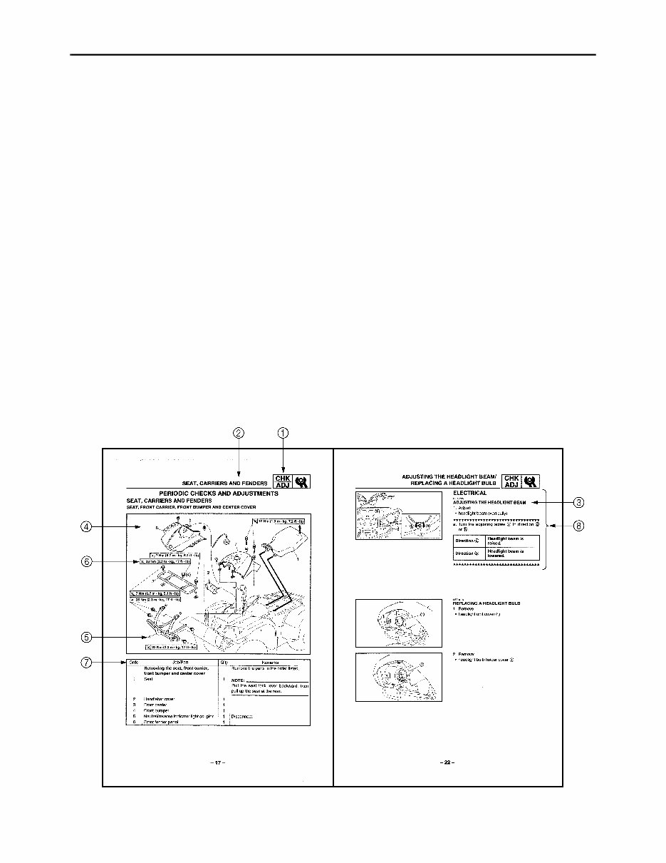
HOW TO USE THIS MANUAL
MANUAL ORGANIZATION
This manual consists of chapters for the main categories of subjects. (See “symbols”)
1st title 1: This is the title of the chapter with its symbol in the upper right corner of each page.
2nd title 2: This title indicates the section of the chapter and only appears on the first page of each
section. It is located in the upper left corner of the page.
3rd title 3: This title indicates a sub-section that is followed by step-by-step procedures accompa-
nied by corresponding illustrations.
EXPLODED DIAGRAMS
To help identify parts and clarify procedure steps, there are exploded diagrams at the start of each
removal and disassembly section.
1. An easy-to-see exploded diagram 4 is provided for removal and disassembly jobs.
2. Numbers 5 are given in the order of the jobs in the exploded diagram. A number that is enclosed
by a circle indicates a disassembly step.
3. An explanation of jobs and notes is presented in an easy-to-read way by the use of symbol marks
6. The meanings of the symbol marks are given on the next page.
4. A job instruction chart 7 accompanies the exploded diagram, providing the order of jobs, names
of parts, notes in jobs, etc.
5. For jobs requiring more information, the step-by-step format supplements 8 are given in addition
to the exploded diagram and the job instruction chart.
- www.instant-manuals.com -
EB003000
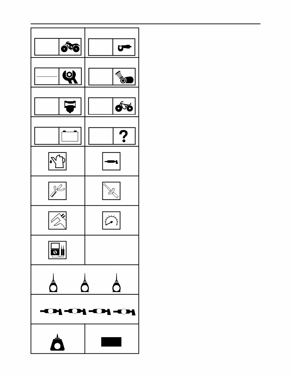
ILLUSTRATED SYMBOLS
Illustrated symbols 1 to 8 are printed on the
top right of each page and indicate the subject
of each chapter.
1 General information
2 Specifications
3 Periodic checks and adjustments
4 Engine
5 Carburetion
6 Chassis
7 Electrical
8 Troubleshooting
Illustrated symbols 9 to E are used to identify
the specifications appearing in the text.
9 Filling fluid
0 Lubricant
A Special tool
B Torque
C Wear limit, clearance
D Engine speed
E Ω, V, A
Illustrated symbols F to L in the exploded
diagrams indicate the types of lubricants and
lubrication points.
F Apply engine oil
G Apply gear oil
H Apply molybdenum disulfide oil
I Apply wheel bearing grease
J Apply lightweight lithium soap base grease
K Apply molybdenum disulfide grease
L Apply silicon grease
Illustrated symbols M to N in the exploded
diagrams indicate where to apply a locking
agent M and when to install a new part N.
M Apply the locking agent (LOCTITE
®
)
N Replace
1 2
3 4
5 6
7 8
9 0
A B
C D
E
F G H
I
M N
GEN
INFO
SPEC
CHK
ADJ
ENG
CARB
CHAS
– +
ELEC
TRBL
SHTG
T
R
.
.
E G M
B
LS M
S
J K L
LT
New
- www.instant-manuals.com -

CONTENTS
SPECIFICATIONS ............................................................................................1
GENERAL SPECIFICATIONS ..................................................................1
MAINTENANCE SPECIFICATIONS .........................................................2
ENGINE ................................................................................................2
CHASSIS ..............................................................................................2
ELECTRICAL ........................................................................................3
CABLE ROUTING .....................................................................................4
PERIODIC CHECKS AND ADJUSTMENTS ..................................................17
SEAT, CARRIERS AND FENDERS ........................................................17
SEAT, FRONT CARRIER, FRONT BUMPER AND CENTER COVER ....17
FRONT GRILL ASSEMBLY AND FRONT FENDER ..........................19
REAR CARRIER AND REAR FENDER ..............................................20
ELECTRICAL ..........................................................................................22
ADJUSTING THE HEADLIGHT BEAMS ............................................22
REPLACING A HEADLIGHT BULB ....................................................22
ELECTRICAL .................................................................................................24
IGNITION SYSTEM .................................................................................24
CIRCUIT DIAGRAM ............................................................................24
CHARGING SYSTEM .............................................................................25
CIRCUIT DIAGRAM ............................................................................25
LIGHTING SYSTEM ................................................................................26
CIRCUIT DIAGRAM ............................................................................26
TROUBLESHOOTING ........................................................................27
SIGNAL SYSTEM ...................................................................................29
CIRCUIT DIAGRAM ............................................................................29
YFM125S WIRING DIAGRAM
- www.instant-manuals.com -
– 1 –
SPEC
SPECIFICATIONS
GENERAL SPECIFICATIONS
Model YFM125S
Model code number 1C51
Dimensions
Overall length 1,710 mm (67.3 in)
Overall width 990 mm (39.0 in)
Overall height 980 mm (38.6 in)
Seat height 705 mm (27.8 in)
Wheelbase 1,080 mm (42.5 in)
Minimum ground clearance 145 mm (5.7 in)
Basic weight
Wet (with oil and a full fuel tank) 152 kg (335 lb)
Dry (without oil and fuel) 144 kg (317 lb)
Maximum load (except vehicle) 100 kg (220 lb)
Fuel
Type Unleaded gasoline only
Fuel tank capacity 7.6 L (1.67 Imp gal, 2.01 US gal)
Reserve amount 1.3 L (0.28 Imp gal, 0.34 US gal)
Spark plug
Type/manufacturer CR7HS/NGK
Spark plug gap 0.6 ~ 0.7 mm (0.024 ~ 0.028 in)
Electrical
Ignition system DC C.D.I.
Generator system A.C. magneto generator
Battery capacity 12V 12Ah
Battery type 12N12C-4A-2
Headlight type Bulb type
Headlight bulb type Krypton
Bulb wattage (quantity)
Headlight 12 V 30 W/30 W (2 pc.)
Tail/brake light 12 V 5 W/21 W (1 pc.)
Neutral indicator light 12 V 1.7 W (1 pc.)
Reverse indicator light 12 V 1.7 W (1 pc.)
GENERAL SPECIFICATIONS
- www.instant-manuals.com -
– 2 –
SPEC
MAINTENANCE SPECIFICATIONS
MAINTENANCE SPECIFICATIONS
ENGINE
CHASSIS
Tightening torques
Model YFM125S
Carburetor
I.D. mark 5VJ2 10
Main jet (M.J) # 77.5
Main air jet (M.A.J) ø 1.3
Jet needle (J.N) 4HPY46-1
Needle jet (N.J) O-1M
Cutaway (C.A) 2.5
Pilot air jet (P.A.J) # 130
Pilot outlet (P.O) ø 0.7
Pilot jet (P.J) # 12.5
Bypass 1 (B.P.1) 1.1
Valve seat size (V.S) 1.8
Starter jet (G.S) # 45
Fuel level (F.L) 3.5 ~ 4.5 mm (0.14 ~ 0.18 in)
With special tool
Engine idling speed 1,650 ~ 1,750 r/min
Intake vacuum 26.7 kPa (200 mmHg, 7.88 inHg)
Part to be tightened Thread size
Tightening torque
Remarks
Nm m · kg ft · lb
Footrest board and footrest bracket M5 7 0.7 5.1
Footrest and footrest bracket M6 10 1.0 7.2
Front fender and frame M6 7 0.7 5.1
Front carrier and front grill M6 7 0.7 5.1
Fuel tank M6 10 1.0 7.2
- www.instant-manuals.com -
– 3 –
SPEC
MAINTENANCE SPECIFICATIONS
ELECTRICAL
Model YFM125S
C.D.I.
Magneto model/manufacturer F1C5/YAMAHA
Pickup coil resistance 248 ~ 372 Ω at 20 °C (68 °F)
(lead color) (white-red)
C.D.I. unit model/manufacturer 3FA/YAMAHA
Charging system
Type A.C. magneto generator
Magneto model/manufacturer F1C5/YAMAHA
Charging coil resistance 0.8 ~ 1.2 Ω at 20 °C (68 °F)
(lead color) (white-white)
Charging current (Minimum) 6.2 A at 1,500 r/min
(Maximum) 13 A at 5,000 r/min
Standard output 14 V 150 W at 5,000 r/min
Rectifier/regulator
Model/manufacturer SH640E-11/SHINDENGEN
Regulator type Semi conductor short circuit type
No load regulated voltage (DC) 14.0 ~ 15.0 V
Rectifier capacity 14.0 A
Withstand voltage 200 V
Electric starting system
Type Constant mesh
Starter motor
Model/manufacturer 3FA/YAMAHA
Output 0.4 kW
Armature coil resistance 0.019 ~ 0.023 Ω at 20 °C (68 °F)
Overall length (brush) 10.0 mm (0.39 in)
<Limit> <3.5 mm (0.14 in)>
Brush spring pressure 552 ~ 828 g
Commutator diameter 22.0 mm (0.87 in)
<Wear limit> <21.0 mm (0.83 in)>
Mica undercut 1.5 mm (0.06 in)
Starter relay
Model/manufacturer MS5E-661/JIDECO
Amperage rating 100 A
Coil resistance 4.18 ~ 4.62 Ω at 20 °C (68 °F)
Starting circuit cut off relay
Model/manufacturer ACA12115-1/MATSUSHITA
Coil resistance 72 ~ 88 Ω at 20 °C (68 °F)
Diode No
Circuit breaker
Type Fuse
Amperage for individual circuit
Main 15 A
- www.instant-manuals.com -
– 4 –
SPEC
CABLE ROUTING
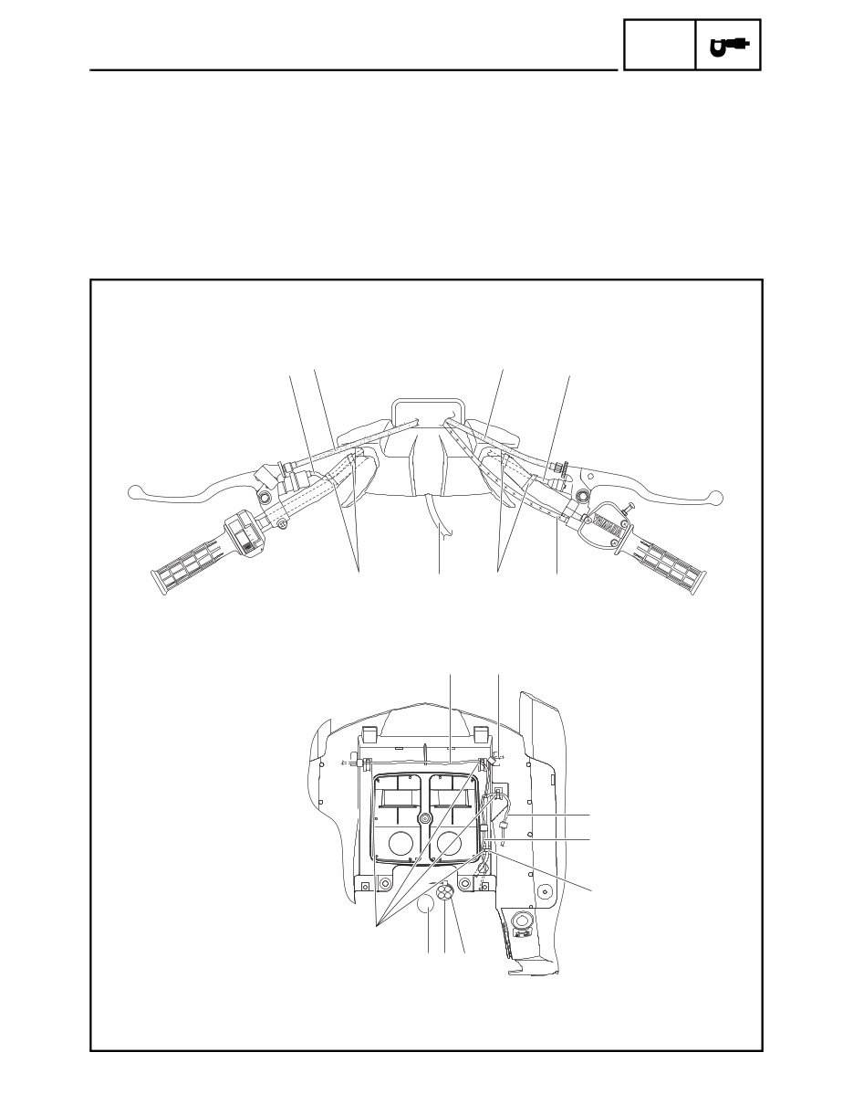
CABLE ROUTING
1 Rear brake switch lead
2 Rear brake cable
3 Front brake cable
4 Front brake switch lead
5 Throttle cable
6 Fuel tank breather hose
7 Headlight lead (left)
8 Headlight lead (right)
9 Neutral/reverse indicator light lead
0 Main switch lead
A Coupler cover
B Steering shaft
OFF RUN
ENG.STOP
LO
HI
0FF
LIGHTS
1 4
2 3
É
8 7
B A
Ë
Ê
Ì
9
0
6 5 È
- www.instant-manuals.com -

– 5 –
SPEC
CABLE ROUTING
È Fasten the front brake switch lead with two plas-
tic bands.
É Fasten the rear brake switch lead and handlebar
switch lead with two plastic bands.
Ê Do not pull the wire harness after fastening it.
Ë When installing the front fender, do not pinch the
coupler cover.
Ì Pass the leads and wire harness through the
guides on the front fender as shown.
OFF RUN
ENG.STOP
LO
HI
0FF
LIGHTS
1 4
2 3
É
8 7
B A
Ë
Ê
Ì
9
0
6 5 È
- www.instant-manuals.com -
– 6 –
SPEC
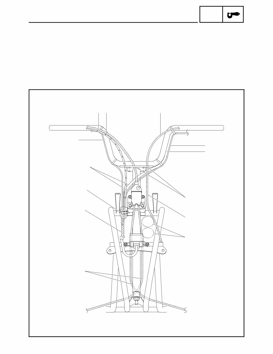
CABLE ROUTING
1 Front brake cable
2 Throttle cable
3 Rear brake cable
4 Rear brake switch lead
5 Handlebar switch lead
6 Wire harness
7 Front brake switch lead
È Pass the front brake cable and rear brake cable
through the cable guide.
É Route the rear brake cable to the inside of the
front fender bracket.
Ê Pass the air duct inlet and outlet hoses between
the brake cables.
Ë Cross the front brake cables behind the steering
shaft. Route the right front brake cable in front of
the left front brake cable.
1 2 3
4
7
5
È
É
Ê
Í
Ë
Ì
6
- www.instant-manuals.com -

– 7 –
SPEC
CABLE ROUTING
Ì Put the cover on the couplers, and then fasten a
plastic band around the middle of the cover.
Í Route the rear brake switch lead and the handle-
bar switch lead behind the throttle cable and the
rear brake cable.
1 2 3
4
7
5
È
É
Ê
Í
Ë
Ì
6
- www.instant-manuals.com -
You're Reading a Preview
What's Included?
Fast Download Speeds
Online & Offline Access
Access PDF Contents & Bookmarks
Full Search Facility
Print one or all pages of your manual
$28.99
Viewed 28 Times Today


Secure transaction
What's Included?
Fast Download Speeds
Online & Offline Access
Access PDF Contents & Bookmarks
Full Search Facility
Print one or all pages of your manual
$28.99
Get your hands on the 2002 Yamaha ATV YFA1(P),YFMA1W Service Manual for comprehensive coverage of the following:
- General Information
- Specifications
- Periodic Checks & Adjustments
- Chassis
- Engine
- Cooling System
- Fuel System
- Electrical System
- Troubleshooting
- Wiring Diagram
This manual is compatible with all versions of Windows & Mac and is available in English language. It comes in a printable file format, allowing you to easily run off the necessary pages for reference in your garage or workshop. Whether you're a professional mechanic or a DIY enthusiast, these step-by-step instructions cater to all skill levels, saving you money on repairs. With instant access upon payment, there are no shipping costs or waiting for a CD to arrive. Secure payment options include major credit/debit cards and PayPal.
For more information, visit: http://www.tradebit.com/visit.php/218358/user/mech


