
 Service and Repair Manual 1986")
1986 Yamaha Moto-4 60 (4-Zinger) Service & Repair Manual
What's Included?
Fast Download Speeds
Online & Offline Access
Access PDF Contents & Bookmarks
Full Search Facility
Print one or all pages of your manual
_YAMAHA
LIT -11616-04-87
1HN-28197-10
NOTICE
This manual was written by the Yamaha Motor Company primarily for use by Yamaha dealers and
their qualified mechanics. It is not possible to put an entire mechanic's education into one manual,
so it is assumed that persons using this book to perform maintenance and repairs on Yamaha motor-
cycles have a basic understanding of the mechanical concepts and procedures inherent in motorcycle
repair technology. Without such knowledge, attempted repairs or service to this model may render
it unfit to use and/or unsafe.
Yamaha Motor Company, Ltd. is continually striving to improve all models manufactured by Yamaha.
Modifications and significant changes in specifications or procedures will be forwarded to all Authorized
Yamaha dealers and will, where applicable, appear in future editions of this manual.
TECHNICAL PUBLICATIONS
SERVICE DIVISION
MOTORCYCLE OPERATIONS
YAMAHA MOTOR CO., LTD
HOW TO USE THIS MANUAL
PARTICULARLY IMPORTANT INFORMATION
This material is distinguished by the following notation.
NOTE:
WARNING:
A NOTE provides key information to make procedures easier or clearer.
A CAUTION indicates special procedures that must be followed to avoid damage
to the motorcycle.
A WARNING indicates special procedures that must be followed to avoid injury
to a motorcycle operator or person inspecting or repairing the motorcycle.
MANUAL FORMAT
All of the procedures in this manual are organized in a sequential, step-by-step format. The informa-
tion has been compiled to provide the mechanic with an easy to read, handy reference that contains
comprehensive explanations of all disassembly, repair, assembly, and inspection operations.
In this revised format, the condition of a faulty component will precede an arrow symbol and the course
of action required will follow the symbol, e.g.,
-Bearings
Pitting/ Damage--+ Replace.
EXPLODED DIAGRAM
Each chapter provides exploded diagrams before each disassembly section for ease in identifying cor-
rect disassembly and assembly procedures.
CD ®
I=I~I
l~g~1 §tl
® ®
IENGI~I
lcooy ~I
@
®
~ARBI.I ~HASI~I
(j)
®
IELEel §I
~pp~6"1
®
~
@
~
QD
~
@
~
@
[0J
(3)
~
@
1
@
1
@
1
m m a
@ @
®
~~ ~sn ~
@
A
B
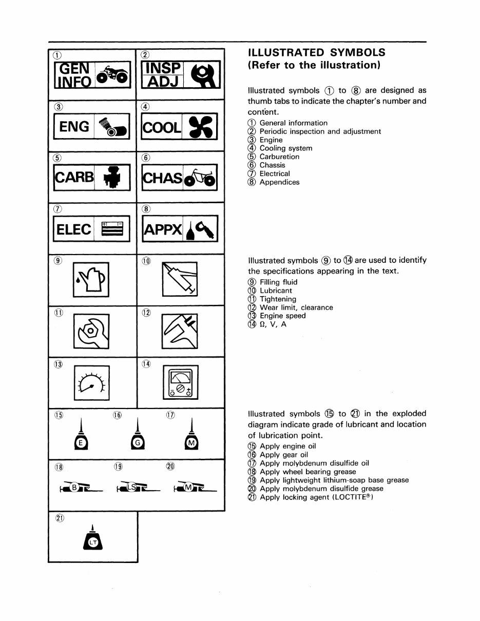
ILLUSTRATED SYMBOLS
(Refer to the illustration)
Illustrated symbols CD to ® are designed as
thumb tabs to indicate the chapter's number and
content.
CD General information
(2) Periodic inspection and adjustment
@ Engine
@ Cooling system
@ Carburetion
® Chassis
(J) Electrical
@ Appendices
Illustrated symbols ® to @ are used to identify
the specifications appearing in the text.
® Filling fluid
® Lubricant
@ Tightening
© Wear limit, clearance
@ Engine speed
@O,V,A
Illustrated symbols @ to @ in the exploded
diagram indicate grade of lubricant and location
of lubrication point.
® Apply engine oil
® Apply gear oil
@ Apply molybdenum disulfide oil
@ Apply wheel bearing grease
@l Apply lightweight lithium-soap base grease
@ Apply molybdenum disulfide grease
@ Apply locking agent (LOCTITE®)
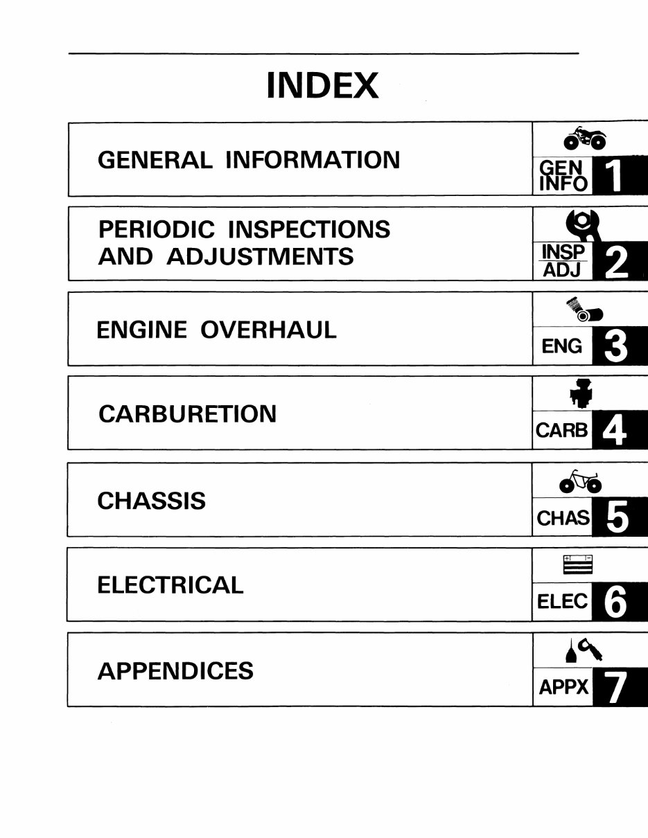
INDEX
GENERAL INFORMATION
fItti;
GEN
INFO
____________________ I~~~I~I
CHAPTER 1.
GENERAL INFORMATION
MACHINE IDENTIFICATION . ...................................... 1-1
VEHICLE IDENTIFICATION NUMBER .............................. 1-1
ENGINE SERIAL NUMBER ....................................... 1-1
IMPORTANT INFORMATION . ..................................... 1-2
ALL REPLACEMENT PARTS ..................................... 1-2
GASKETS, OIL SEALS, AND O-RINGS ............................ 1-2
LOCK WASHERS/PLATES AND COTTER PINS .................... 1-2
BEARINGS AND OIL SEALS ..................................... 1-2
CIRCLIPS ...................................................... 1-3
SPECIAL TOOLS .................................................. 1-3
FOR TUNE-UP .................................................. 1-3
FOR ENGINE SERVICE .......................................... 1-3
FOR CHASSIS SERViCE ......................................... 1-5
FOR ELECTRICAL COMPONENTS ................................ 1-5
I ~~ IAI MACHINE IDENTIFICATION
1-1
GENERAL
INFORMATION
MACHINE IDENTIFICATION
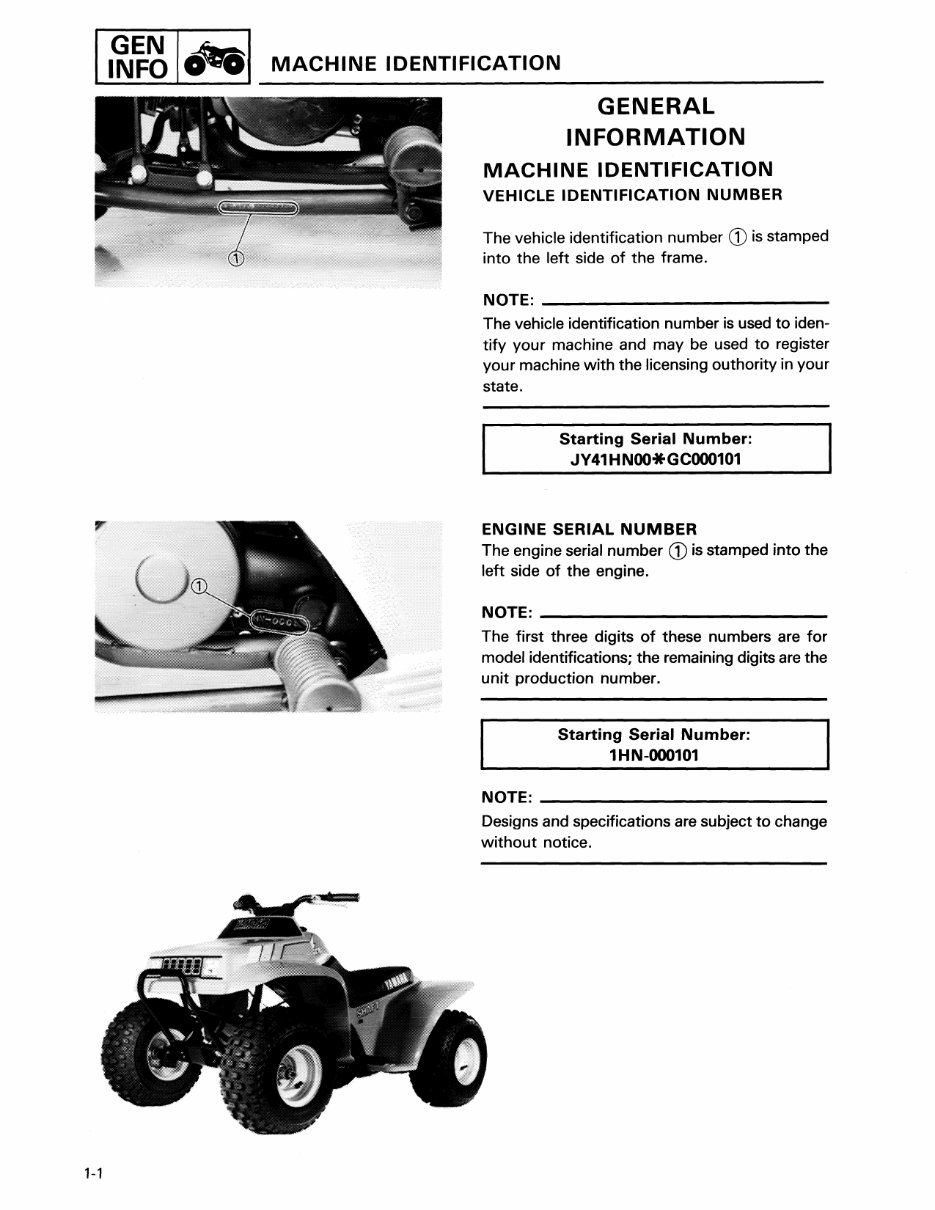
VEHICLE IDENTIFICATION NUMBER
The vehicle identification number CD is stamped
into the left side of the frame.
NOTE: ________________________ _
The vehicle identification number is used to iden-
tify your machine and may be used to register
your machine with the licensing outhority in your
state.
Starting Serial Number:
JY41HNOO*GCOOO101
ENGINE SERIAL NUMBER
The engine serial number CD is stamped into the
left side of the engine.
NOTE: ______________________ __
The first three digits of these numbers are for
model identifications; the remaining digits are the
unit production number.
Starting Serial Number:
1HN-000101
NOTE: ________________________ _
Designs and specifications are subject to change
without notice.
IMPORTANT INFORMATION I,~~ Icteal
IMPORTANT INFORMATION
300-000
ALL REPLACEMENTS PARTS
1. We recommend to use Yamaha genuine parts
for all replacements. Use oil and/or grease
recommended by Yamaha for assembly and
adjustment.
GASKETS, OIL SEALS, AND a-RINGS
1. All gaskets, seals, and a-rings should be
replaced when an engine is overhauled. All
gasket surfaces, oil seal lips, and a-rings must
be cleaned.
2. Properly oil all mating parts and bearings dur-
ing reassembly. Apply grease to the oil seal
lips.
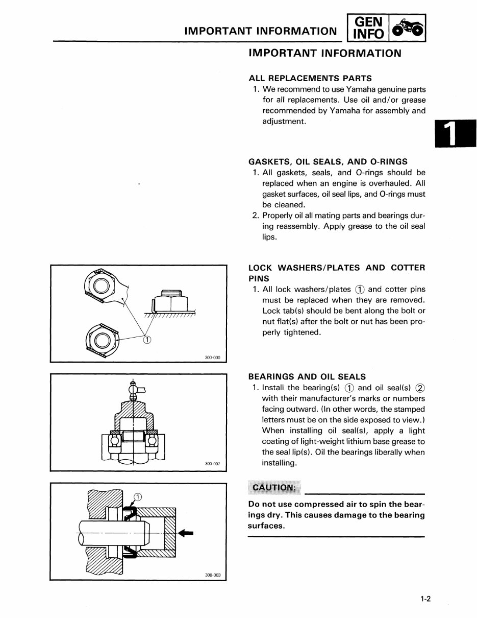
LOCK WASHERS/PLATES AND COTTER
PINS
1. All lock washers/plates CD and cotter pins
must be replaced when they are removed.
Lock tab(s) should be bent along the bolt or
nut flat(s) after the bolt or nut has been pro-
perly tightened.
BEARINGS AND OIL SEALS
1. Install the bearing(s) CD and oil seal(s) CV
with their manufacturer's marks or numbers
facing outward. (In other words, the stamped
letters must be on the side exposed to view.)
When installing oil seal(s), apply a light
coating of light-weight lithium base grease to
the seallip(s). Oil the bearings liberally when
300 OO? installing.
300-003
Do not use compressed air to spin the bear-
ings dry. This causes damage to the bearing
surfaces.
1-2
I,~~~ I AI SPECIAL TOOLS
1-3
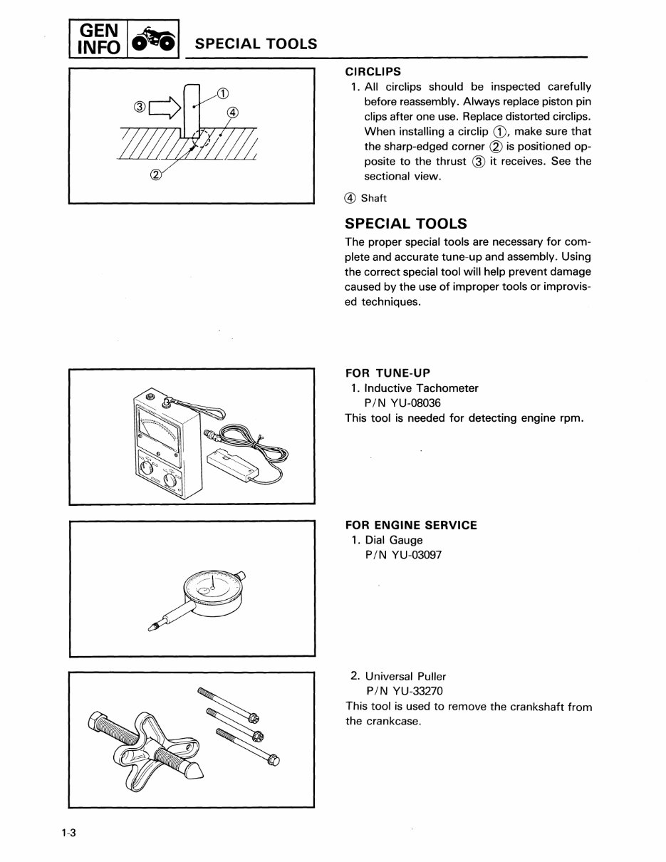
CIRCLIPS
1. All circlips should be inspected carefully
before reassembly. Always replace piston pin
clips after one use. Replace distorted circlips.
When installing a circlip CD, make sure that
the sharp-edged corner (2) is positioned op-
posite to the thrust ® it receives. See the
sectional view.
@ Shaft
SPECIAL TOOLS
The proper special tools are necessary for com-
plete and accurate tune-up and assembly. Using
the correct special tool will help prevent damage
caused by the use of improper tools or improvis-
ed techniques.
FOR TUNE-UP
1. Inductive Tachometer
P/ N YU-08036
This tool is needed for detecting engine rpm.
FOR ENGINE SERVICE
1. Dial Gauge
P/ N YU-03097
2. Universal Puller
P/ N YU-33270
This tool is used to remove the crankshaft from
the crankcase.
SPECIAL TOOLS I ~~ I ~I
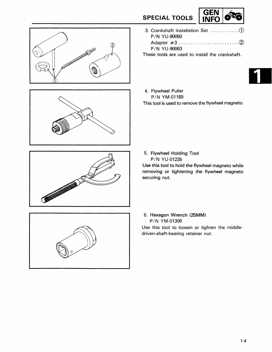
3. Crankshaft Installation Set ............ CD
PIN YU-90050
Adapter # 3 ......................... <bl
PIN YU-90063
These tools are used to install the crankshaft.
4. Flywheel Puller
PIN YM-01189
This tool is used to remove the flywheel magneto.
5. Flywheel Holding Tool
PIN YU-01235
Use this tool to hold the flywheel magneto while
removing or tightening the flywheel magneto
securing nut.
6. Hexagon Wrench (25MM)
PIN YM-01306
Use this tool to loosen or tighten the middle-
driven-shaft-bearing retainer nut.
1-4
II~~ 1cJe81 SPECIAL TOOLS
'II __ -~I
L-. -- __ II
I
1-5
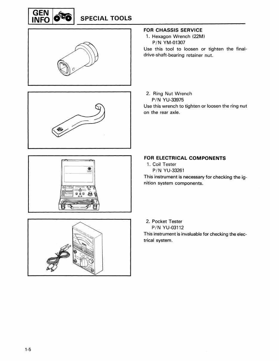
FOR CHASSIS SERVICE
1. Hexagon Wrench (22M)
PIN YM-01307
Use this tool to loosen or tighten the final-
drive-shaft-bearing retainer nut.
2. Ring Nut Wrench
PIN YU-33975
Use this wrench to tighten or loosen the ring nut
on the rear axle.
FOR ELECTRICAL COMPONENTS
1. Coil Tester
PIN YU-33261
This instrument is necessary for checking the ig-
nition system components.
2. Pocket Tester
PIN YU-03112
This instrument is invaluable for checking the elec-
trical system.
You're Reading a Preview
What's Included?
Fast Download Speeds
Online & Offline Access
Access PDF Contents & Bookmarks
Full Search Facility
Print one or all pages of your manual
$24.99
Viewed 53 Times Today


Secure transaction
What's Included?
Fast Download Speeds
Online & Offline Access
Access PDF Contents & Bookmarks
Full Search Facility
Print one or all pages of your manual
$24.99
Yamaha Moto-4 60 (4-Zinger) Service and Repair Manual
Covers: 1986
Instant access to the factory repair manual for the 1986 Yamaha Moto-4 60 youth ATV, also known as the 4-Zinger. This manual covers complete tear down and rebuild, including pictures and part diagrams, torque specs, maintenance, troubleshooting, and more. It consists of 151 pages and features clickable chapters, making it searchable for easy navigation. There are no restrictions on printing or saving/burning to disc.


