

TGB TARGET 400 425 ATV Full Service & Repair Manual
What's Included?
Fast Download Speeds
Offline Viewing
Access Contents & Bookmarks
Full Search Facility
Print one or all pages of your manual
Home page Contents
17. ELECTRICAL SYSTEM
Mechanism Diagram ·························· 17-1
Maintenance Data ······························· 17-2
Technical Specification······················17-2
Trouble Diagnosis ······························ 17-3
Battery ················································· 17-4
Charging System ································ 17-5
Ignition System··································· 17-8
Starting System ·································· 17-10
Meters ················································· 17-12
Light / Bulb········································· 17-13
Switch / Horn······································ 17-16
Fuel Unit ············································· 17-19
Cooling Fan Thermo Switch ············· 17-20
Thermo unit········································ 17-21
Water Temperature Indicator Light ·· 17-21
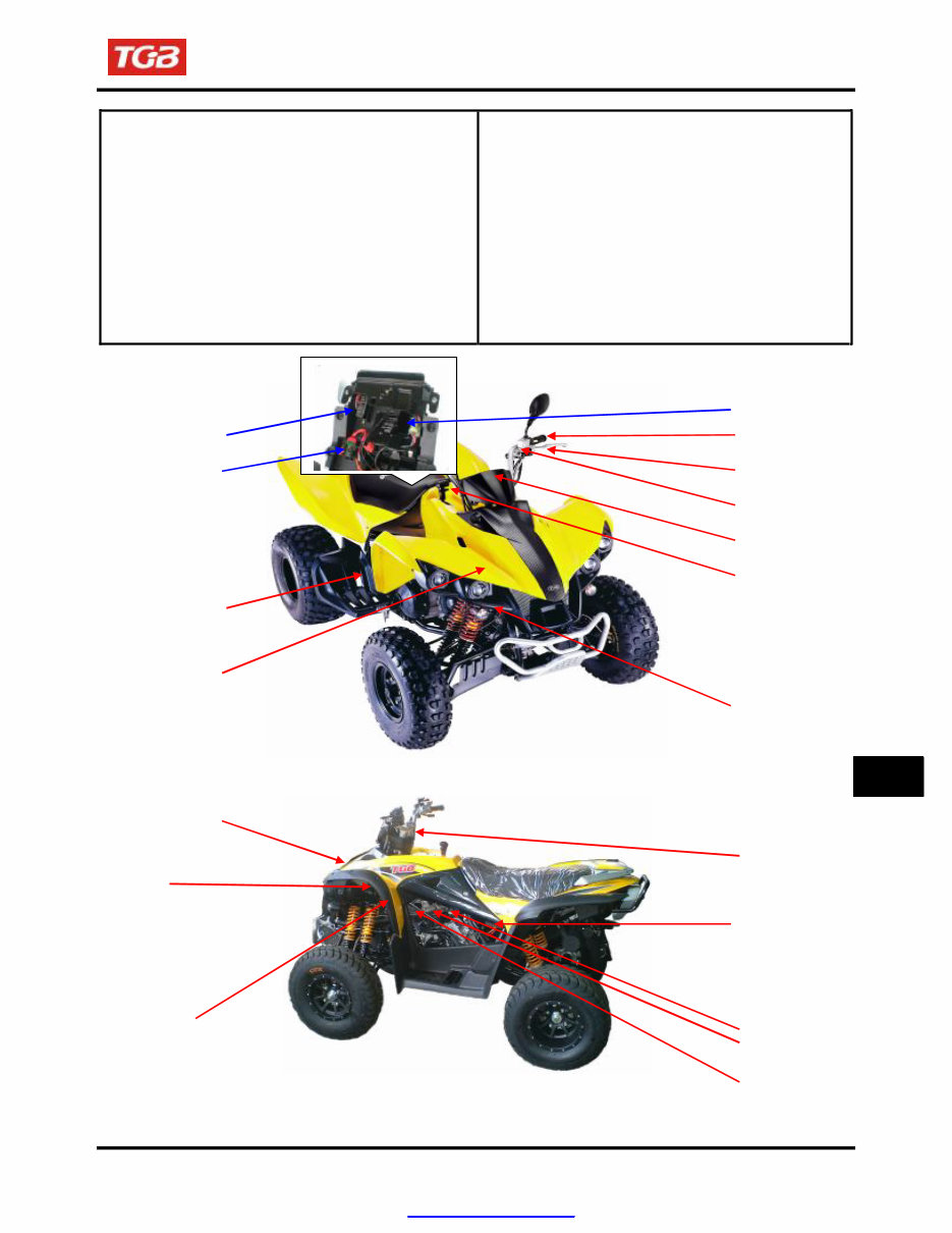
Mechanism Diagram
Battery
Fuse box Front brake switch
Starter relay
Hazard
control unit
Winker relay
Main switch
Shift gear
control unity
Rear brake switch
C.D.I. Unitx
Thermo unit
Headlight relay
Start & light &
winker & horn &
brake switch
Horn
Rectifier
Ignition coil
AC.Generator
Spark plug
Change switch
17-1
17
PDF created with pdfFactory Pro trial version www.pdffactory.com
To this chapter contents
17. ELECTRICAL SYSTEM
Maintenance Data
Operational precaution
● When remove the battery, the disconnection sequence of cable terminals shall be strictly observed.
(First disconnect the negative cable terminal, next, the positive cable terminal.)
● The model of the spark plug and the tightening torque.
● The ignition timing.
● Adjustment of headlight.
● Removal and installation of AC generator.
● The maintenance free battery requires no inspection of electrolyte level and refilling of distilled water.
● To recharge the battery, remove the battery from rack without removing ventilation caps.
● Unless in emergency, never rapid charge the battery.
● The voltage must be checked with the voltmeter while charging the battery.
● As C.D.I assembly does not require an ignition timing check. In case ignition timing is incorrect, check
C.D.I and AC generator. Verify with an ignition timing light after replacement if necessary.
Technical Specification
Charging system
Description Specification
Battery
Capacity 12V18Ah
Charging rate 1.4A / 5 ~ 10 hours (standard)
14A / 0.5 hour (fast charging)
Leak current < 1mA
Charging current 1.2 A / 1500rpm
Control voltage in charging 14.5 + 0.5 V / 1500rpm
Ignition system
Description Specification
Spark plug
Ignition coil and
Model NGK CR7E (Recommended)
Gap 0.8mm
Primary winding 2.9 ± 10%Ω
Without cap: 15. ± 10KΩ
resistance
Secondary winding
Ignition timing “F” mark
With cap:20 ± 10KΩ
15° TDC / 1700rpm
46°TDC / 4200rpm
17-2
PDF created with pdfFactory Pro trial version www.pdffactory.com

To this chapter contents
17. ELECTRICAL SYSTEM
Trouble Diagnosis
No voltage
● Battery discharged
● The cable disconnected
● The fuse is blown
● Improper operation of the main switch
Low voltage
● The battery is not fully charged
● Poor contact
● Poor charging system
● Poor voltage regulator
No spark produced by spark plug
● The spark plug is out of work
● The cable is poorly connected, open or
short-circuited
- Between AC.G. and C.D.I.
● Poor connection between C.D.I. and ignition
coil
- Poor connection between C.D.I. and the
main switch
● Poor main switch
● Poor C.D.I.
● AC.G. is out of work
Starter motor does not work
● The fuse is blown
● The battery is not fully charge
● Poor main switch
● Poor starter switch
● The front and rear brake switches do not
operate correctly
● Starter relay is out of work
● The ignition coil is poorly connected, open or
short-circuited
● The starter motor is out of work
Intermittent power supply
● The connector of the charging system becomes
loose
● Poor connection of the battery cable
● Poor connection or short-circuit of the
discharging system
● Poor connection or short-circuit of the power
generation system
Charging system does not operate
properly
● Burnt fuse
● Poor contact, open or short circuit
● Poor regulator
● Poor ACG
Engine does not crank smoothly
● Primary winding circuit
- Poor ignition coil
- Poor connection of cable and connectors
- Poor main switch
● Secondary winding circuit
- Poor ignition coil
- Poor spark plug
- Poor ignition coil cable
- Current leakage in the spark plug
● Incorrect ignition timing
- Poor AC.G.
- Improper installation of the pulse sensor
- Poor C.D.I.
Weak starter motor
● Poor charging system
● The battery is not fully charged
● Poor connection in the windings
● The motor gear is jammed by foreign material
Starter motor is working, but engine does
not crank
● Poor starter motor pinion
● The starter motor run in reverse direction
● Poor battery
17-3
PDF created with pdfFactory Pro trial version www.pdffactory.com
To this chapter contents
17. ELECTRICAL SYSTEM
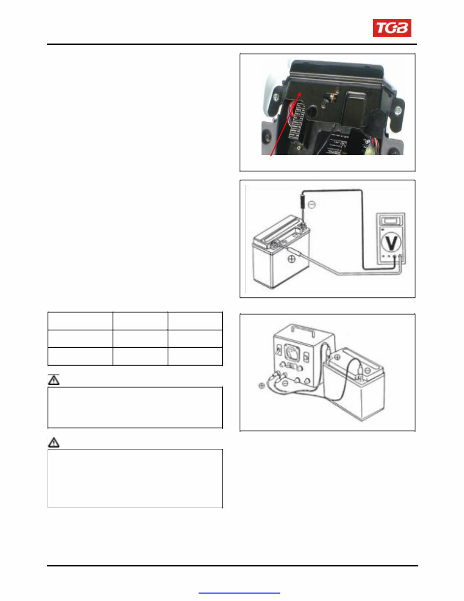
Battery
Removal
Remove the seat, and then you can see the
battery.
Disconnect the negative cable terminal first, then
the positive cable terminal.
Remove the battery clamp, and then remove
battery.
Clamp
Voltage Check
Use the digital voltmeter to check the voltage of
the battery.
Voltage:
Fully charged: 13.0~13.2 V at 20℃
Undercharged: Below 12.3 V at 20℃
Charging
Connect the positive terminal (+) of the charger to
the battery positive terminal (+).
Connect the negative terminal (-) of the charger to
the battery negative terminal (-).
Standard Maximum
Charging current 1.8A 18.0A
Charging time 5H 0.5H
Warning
● Keep flames away while recharging.
● Charging is completely controlled by the
ON/OFF switch on the charger, not by
battery cables.
Caution
● Never rapid charge the battery unless in
emergency.
● Verify the battery is recharged with current
and duration prescribed above.
● Large current and fast time to charge will
render damage to the battery.
When installing the battery, coat the cable terminal
with grease.
17-4
PDF created with pdfFactory Pro trial version www.pdffactory.com
To this chapter contents
17. ELECTRICAL SYSTEM
Charging System
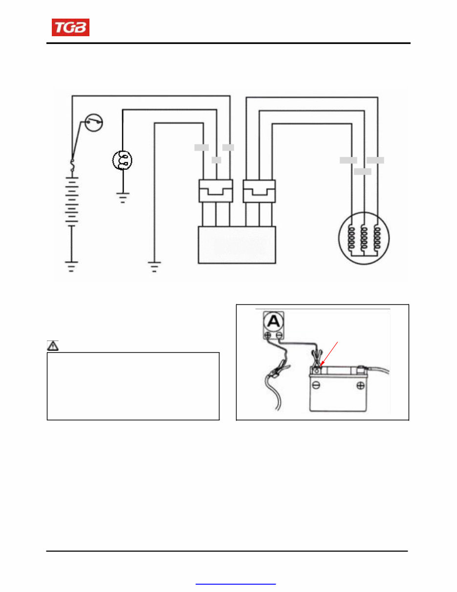
Charging circuit
Main switch
Black Blue
B/R Yellow Yellow
Yellow
Battery
Regulator rectifier
AC. Generator
Current Leakage Inspection
Turn the main switch to OFF position, and remove
the negative cable terminal (-) from the battery.
Connect an ammeter between the negative cable
terminal and the battery negative terminal.
Caution
● In the current leakage test, set the current
range at the largest scale, then gradually
decrease to the lower scale as the test
process goes to avoid possible damage to
the ammeter and the fuse.
● Do not turn the main switch to ON position
during test.
If the leaked current exceeds the specified value, it
may indicate a short circuit.
Allowable current leakage: Less than 1mA
Disconnect each cable one by one and take
measurement of the current of each cable to
locate the short circuit.
Battery negative terminal
17-5
Fuse 20A
PDF created with pdfFactory Pro trial version www.pdffactory.com
To this chapter contents
17. ELECTRICAL SYSTEM
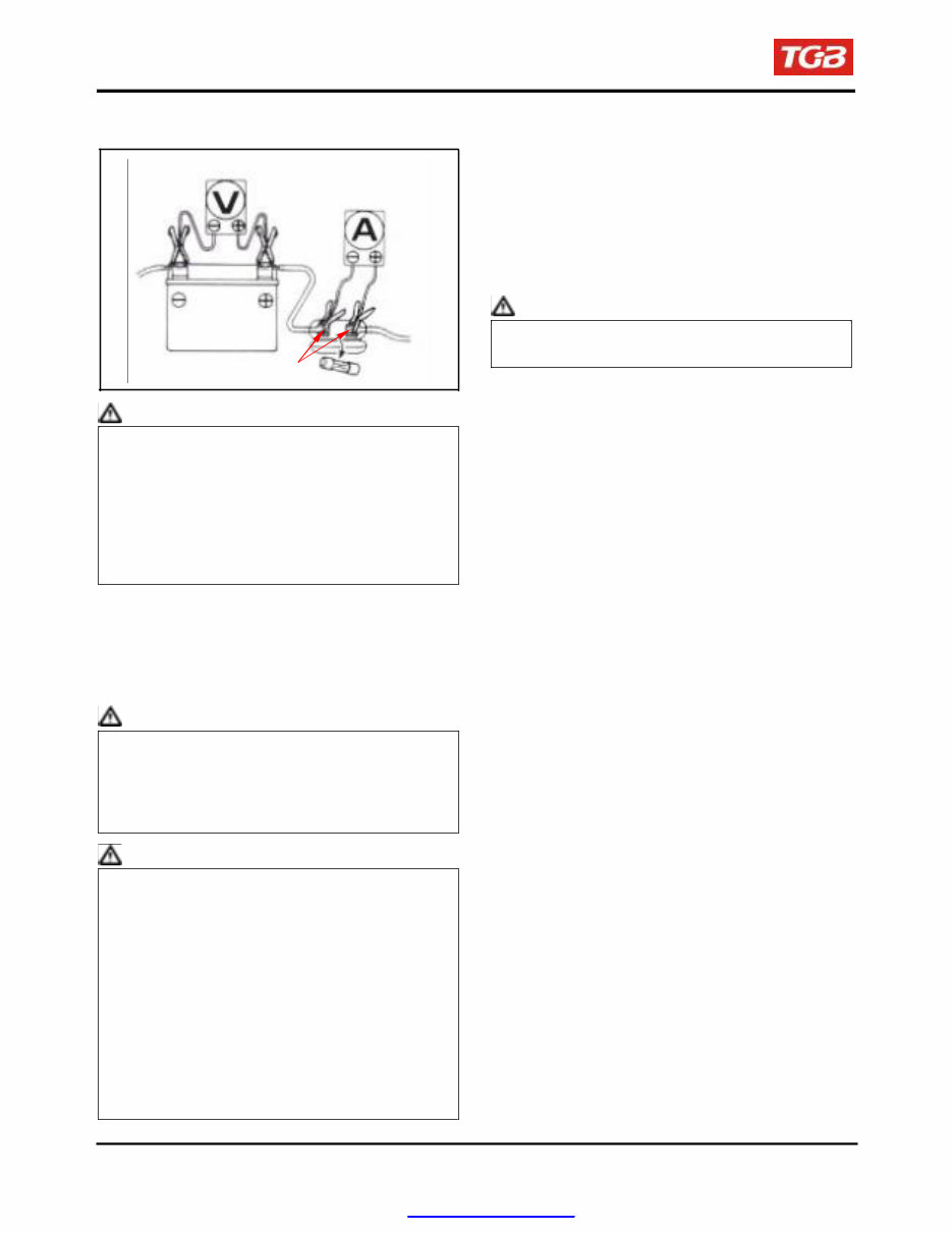
Inspection on Charging Voltage
Voltmeter
Ammeter
Connect a tachometer.
Turn on the headlight to high beam and start the
engine.
Accelerate the engine to the specified revolution
per minute and measure the charging voltage.
Specified Charging Current:
1.2 A / 6000 rpm
Control Charging Voltage:
14.5 + 0.5 V / 2000 rpm
Fuse connector
Caution
To replace the old battery, use a new battery with
the same current and voltage.
Caution
● Before conducting the inspection, be sure that
the battery is fully charged. If undercharged, the
current changes dramatically.
● Use a fully charged battery having a voltage
larger than 13.0 V
● While starting the engine, the starter motor
draws large amount of current from the
battery.
After the engine is warmed up, replace original
battery with a fully charged battery.
Connect a digital voltmeter to the battery
terminals.
Connect an ammeter between both ends of the
main fuse.
Caution
When the probe is reversibly connected, use a
voltmeter having an indication that the current
flows from the positive or the negative direction
and the measurement should be at zero,
ammeter at one direction only.
Caution
● Does not use short-circuit cable.
● It is possible to measure the current by
connecting an ammeter between the battery
positive terminal and the cable position
terminal, however, while the starter motor is
activated, the surge current the motor draws
from the battery may damage the ammeter.
Use the kick starter to start the engine.
● The main switch shall be turned to OFF position
during the process of inspection. Never tamper
with the ammeter and the cable while there is
current flowing through. It may damage the
ammeter.
The following problems are related to the charging
system; follow the instructions provided in the
checking list to correct it if any one of the problems
takes place.
(1) The charging voltage can not exceed the
voltage between two battery terminals and
the charging current is in the discharging
direction.
(2) The charging voltage and current are too
much higher than the standard values.
The following problems are not related to the
charging system; correct it if any by following
steps indicate in the checking list.
(1) The standard charging voltage and current
can only reach when the revolution of the
engine exceeds the specified rpm.
- Bulbs used exceed their rate and
consume too much power.
- The replacement battery is aged and
does not have enough capacity.
(2) The charging voltage is normal, but the
current is not.
- The replacement battery is aged and
does not have enough capacity.
- Battery used does not have enough
electricity or is over charged.
- The fuse of the ammeter is blown.
- The ammeter is improperly connected.
(3) The charging current is normal, but the
voltage is not.
- The fuse of the voltmeter is blown.
17-6
PDF created with pdfFactory Pro trial version www.pdffactory.com
To this chapter contents
17. ELECTRICAL SYSTEM
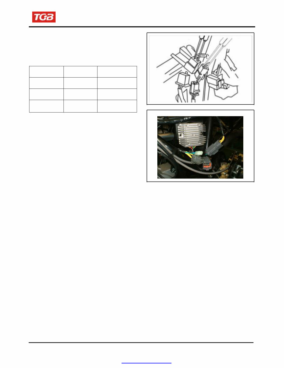
Inspection on regulator rectifier
Remove the seat, rear carrier and rear fender.
Disconnect two 3 pin couplers of the regulator
rectifier.
Inspection the rectifier coupler to the wire harness
passes the condition.
Item Check Points Standard Value
Main switch
connection Bl – B
Battery
Battery voltage
(ON)
connection Bl – B Battery voltage
Charging coil B – B 0.1 ~ 0.5Ω
If the readings measured are not normal, check
parts in the circuit.
If the parts are normal, then trouble is in the wiring. If
there is nothing wrong with parts and wiring, replace
the regulator rectifier.
17-7
PDF created with pdfFactory Pro trial version www.pdffactory.com
To this chapter contents
17. ELECTRICAL SYSTEM
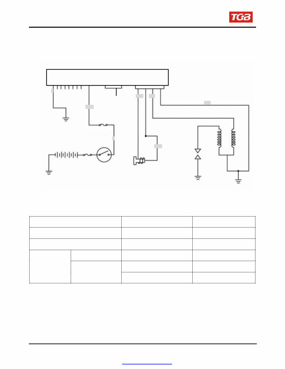
Ignition System
Ignition circuit diagram
C D I Unit
B
B Black
R Red
G Green
W White
Y Yellow
L Blue
BR/B
Fuse 10A
Main fuse
20A
Spark plug
Ignition
coil
Battery
Main switch
G
Pulse generator
C.D.I unit
Disconnect connectors of the C.D.I unit.
Check the following connectors as indicated in the table at the harness side.
Item Points to check Result
Main switch turn to “ON” position Br/Bl ~ B Battery voltage
Pulse generator Bl/Y ~ G/R 50~170Ω
Primary circuit G/R ~ B 2.9±10%Ω
Ignition coil
Secondary circuit
TERMINAL-B ~ with no cap 15.0±10%Ω
TERMINAL-B ~ with cap 20.0±10%KΩ
17-8
C D I Unit
G/R B1/Y
LG/R
B
B/W
PDF created with pdfFactory Pro trial version www.pdffactory.com
To this chapter contents
17. ELECTRICAL SYSTEM
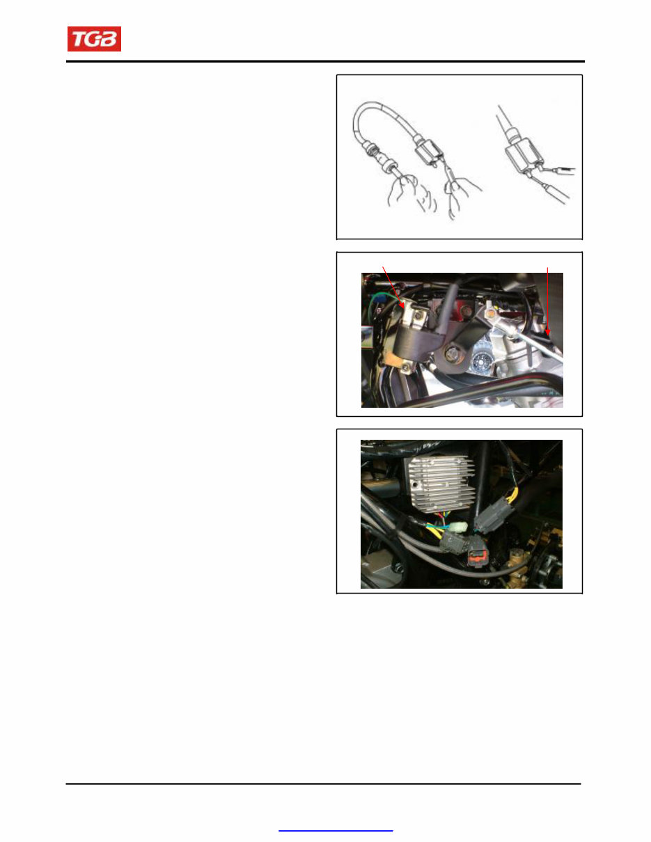
Inspection on Ignition Coil
Disengage the connector of the ignition coil and
the spark plug cap.
Measure the resistance between the terminals of
the primary winding.
Standard resistance: 2.9Ω ± 10%
Remove the cap from the spark plug and measure
the resistance between the spark plug and the
primary winding.
Standard resistance:
With no cap: 15.0Ω ± 10%
With cap: 20.0±10%KΩ
Ignition Coil Replacement
Loosen the lock bolt and replace the ignition coil if
necessary.
Inspection of Pulse Generator
Disconnect the coupler of the pulse generator and
measure the resistance between the terminals of
green/white and blue/yellow.
Standard resistance: 50~170Ω
Ignition coil
Spark plug
17-9
PDF created with pdfFactory Pro trial version www.pdffactory.com
To this chapter contents
17. ELECTRICAL SYSTEM
Starting System
Starting circuit diagram
C.D.I
W
B/W
Fuse 15A
B
Main switch
R
Main fuse
30A
F
N
R
G/Y
Brake
switch
Battery
Change switch
B1 Blue
B Black
R Red
G Green
W White
Y Yellow
BR Brown
Starter switch
Starter relay
Starter motor
G
G/Y
Brake light
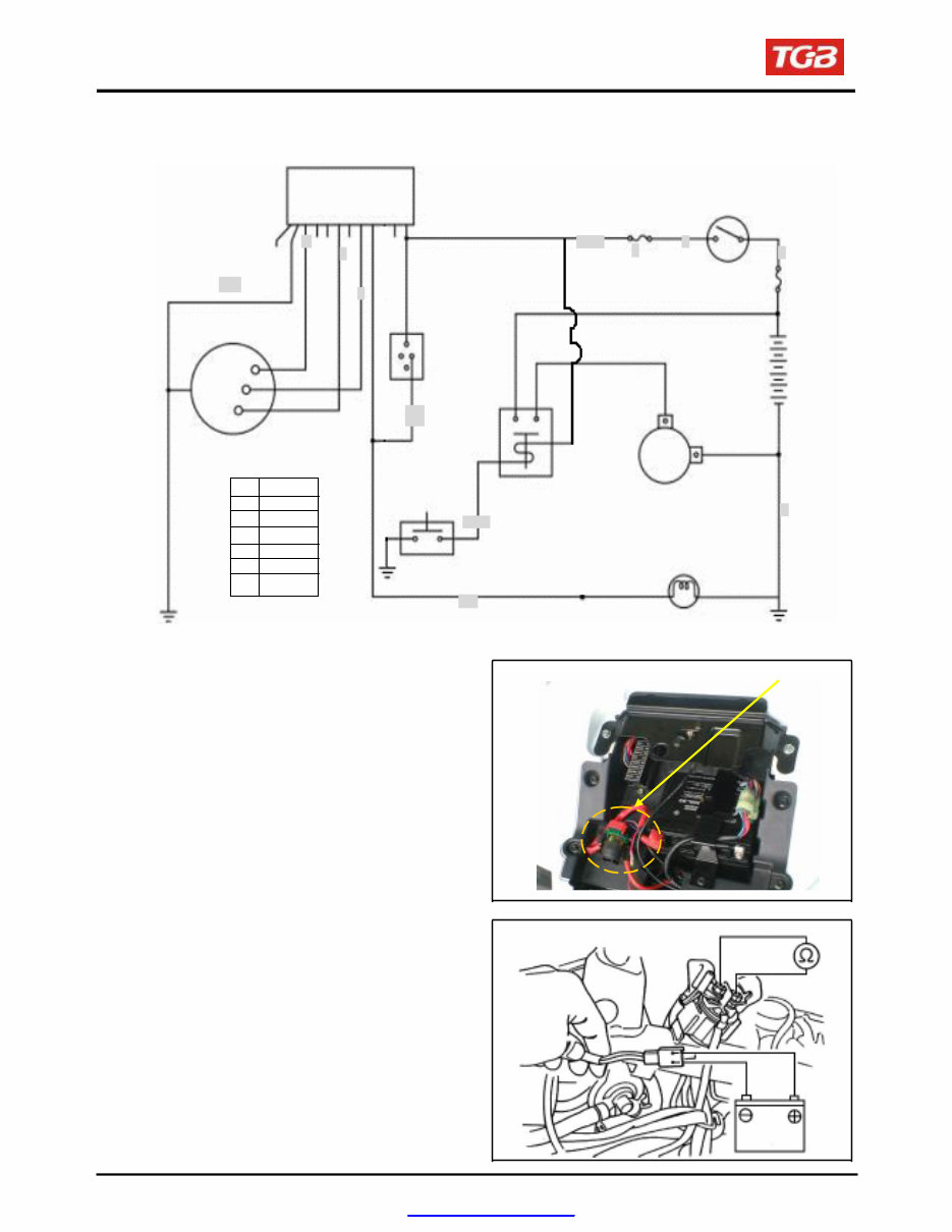
Inspection on starter relay
Open the main switch.
Press the brake.
Push down the starter switch.
If a sound of “ Looh Looh” is heard, it indicates the
relay function normally.
Remove the seat.
Disconnect the negative cable terminal of the
battery.
Disconnect the cable positive terminal from the
relay.
Disconnect the positive cable of the starter motor.
Disconnect the coupler of the relay.
Connect an ohmmeter to the large terminal end.
Connect the yellow/red cable to the battery positive
terminal and the black / blue cable to the battery
negative terminal.
Check the continuity of the large terminal end. If
there is no continuity, replace the relay.
17-10
Starter relay
BR/B
B1/W
R
B
B
PDF created with pdfFactory Pro trial version www.pdffactory.com
You're Reading a Preview
What's Included?
Fast Download Speeds
Offline Viewing
Access Contents & Bookmarks
Full Search Facility
Print one or all pages of your manual
$31.99
Viewed 17 Times Today


Secure transaction
What's Included?
Fast Download Speeds
Offline Viewing
Access Contents & Bookmarks
Full Search Facility
Print one or all pages of your manual
$31.99
Get instant access to the Complete Factory Service Repair Workshop Manual without any extra fees or expiry dates. This Professional Manual is suitable for both professional Mechanics and Technicians, as well as DIY enthusiasts. It covers all repairs, servicing, and troubleshooting procedures with detailed photos, diagrams, step-by-step instructions, and highly detailed exploded diagrams & pictures to ensure every job is completed correctly.
Print out a single page or the entire manual as per your choice. This Manual can be used on multiple computers without any limitations or trial periods, and it does not expire or require any renewal fees. It is fully compatible with all Windows & MAC Computers.


