1996-1998 Polaris Sportsman 500 Service & Repair Manual
What's Included?
Lifetime Access
Fast Download Speeds
Online & Offline Access
Access PDF Contents & Bookmarks
Full Search Facility
Print one or all pages of your manual
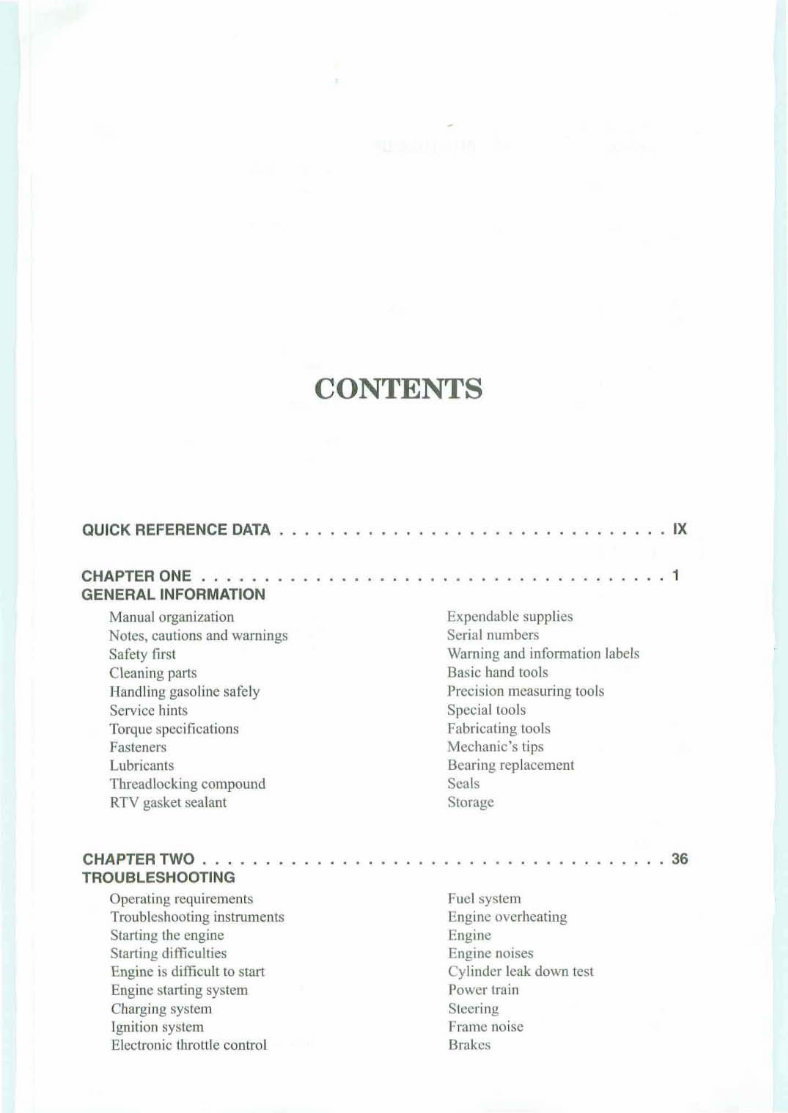
CONTENTS QUICK REFERENCE DATA ........ •...•.• .............. • . IX CHAPTER ONE . GENERAL INFORMATION Manual organization Notes, cautions and warnings Safety first Cleaning parts Handling gasoline saf ely Service hints Torque sped fications Fasteners Lubricants Threadlocking compound RTV gasket sealant CHAPTER TWO ..... TROUBLESHOOTING Operating requirements Troubleshooting instruments Starting the engine Starting diffi culties Engine is difficult to start Engine starting system Charging system Ignition system Electronic throttle control .. .. .. .1 Expendable supplies Serial numbers Warning and information labels Basic hand tools Precision measuring tools Special tools Fabricating tools Mechanic's tips Beari ng replacement Seals Storage .. 36 Fuel sys tem Engine overheating Engine Engine noises Cy linder leak down test Powe r tra in Steering Frame noise Brakes
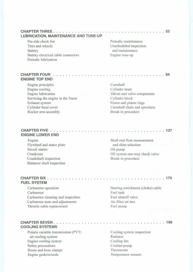
CHAPTER THREE . .. .... .. .. •. •.. . LUBRICATION, MAINTENANCE AND TUNE-UP Pre- ride check list Tire s and whee ls Battery Battery electrical cabl e connectors Periodic lubrication CHAPTER FOUR . ENGINE TOP END Eng ine prin cip les Engine cooling Eng ine lubrication Servicing the engine in the frame Exhaust system Cylinder head cover Rocker ann assembly CHAPTER FIVE . . • . ENGINE LOWER END Engine Flywheel and stator plate Recoi l starter Crankcase Crankshaft inspection Balancer shaft inspection CHAPTER SIX • .... FUEL SYSTEM Carburetor operation Carburetor Carburetor cleaning and inspection Carburetor tests and adjustments Throttle cable replacement CHAPTE R SEVEN. ........ • COOLING SYSTE MS Polaris variable transmission (PVT) air cooling system Eng ine cooling system Safety precauti ons Hoses and hose clamps Engin e gaskets/sea ls .... .. 53 Periodic main tenance Unscheduled inspection and maint enan ce Engine tune-up .. .. .. ...... 94 Camshaft Cy linde r head Valves and valve components Cylinder block Piston and piston rings Camshaft chain and sprockets Break-in procedure . . . 137 Shan end float measurement and shim selection Oil pumr Oil system one-way check valve Break-in procedu re 175 Stall ing enrichment (choke) cab le Fuel tank Fuel shutoff valve Air filter air box Fu ~l pllm p .... 198 Coo ling system inspection Radiator Coo ling fan Coo lant pump Thermostat Temperature sensors
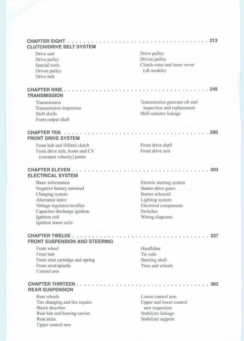
CHAPTER EIGHT . CLUTCH/DRIVE BELT SYSTEM Drive unit Drive pulley Specia l tools Driven pulley Drive belt CHAPTER NINE . TRANSMISSION Tra nsmission Tra nsmission inspection Shift shafts Front output shaft CHAPTER TEN ....... FRONT DRIVE SYSTEM Front hub and Hillard clutch Front drive axle, boots and CV (constant velocity) joints CHAPTER ELEVEN .. ELECTRICAL SYSTEM Ba sic informat ion Negative battery terminal Charging system Alterna tor stator Voltage regulator/rectificr Capacitordischarge ignition Ignition coil Ignition stator coils CHAPTER TWELVE . FRONT SUSPENSION AND STEERING Front wheel Front hub Front strut cartridge and spring Front strut/spindle Control arm CHAPTER THIRTEEN . REAR SUSPENSION Rear wheels Tire changing and tire repairs Shock absorber Rear hub and bearing carrier Rear axles Upper control arm . .. .. .. .... 213 Drive pulley Driven pulley Clutch outer and inner cover (all models) . . 249 Transmission gearcase oil seal inspection andreplacement Shift selector linkage ..... .... 290 Front drive shaft Front drive unit .. .. . 303 Electric starting system Starter drive gears Starter solenoid Lighting system Electrical components Sw itches Wi ring dia grams . 337 Handlebar Tie rods Steerin g shaft Tires and wheels . 362 Lower control arm Upper and lower control arm inspection Stabilizer linkage Stabilizer support
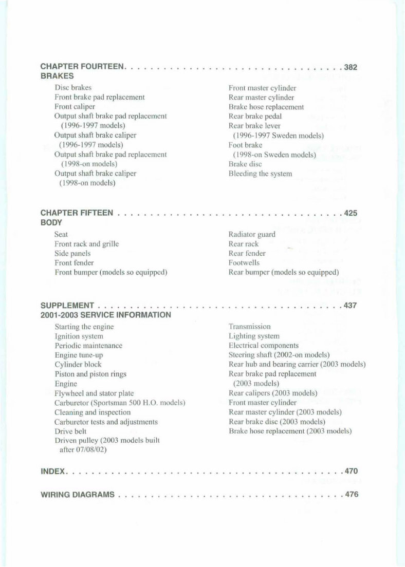
CHAPTER FOURTEEN. BRAKES Disc brakes Front brake padreplacement Fro nt cal iper Ou tput shaft brake pad replacement (199 6-1997 models) O utput shall brake cal iper (] 996- 1997 models) Outpu t shall brake pad replacement (I998-on models) Outp ut shaft brake caliper (I 998-on models) CHAPTER FIFTEEN BODY Seat F ront rack and grille Side pan els Front fender Front bumper (models so equipped) SUPPLEMENT . 2001-2003 SERVICE INFORMATION Starting the engine Ignition system Periodic maintenance Engine tUIl C- Up Cylinder block Piston and piston rings Engine Fl ywhee l and stator plate Carburetor (Sportsman 500 H.G. models) Cleaning and inspection Carburetor tests and adjustments Drive belt Driven pulley (2003 models bui lt after 07/08102) INDEX . WIRING DIAGRAMS . .. . .. . . 382 Fron t master cylinder Rear master cylinder Brake hose replacement Rear brake pedal Rem brake lever (1996-1997 Sweden models) Foot brak e (1998-on Sweden model s) Brake disc Bleeding the system ... .. .. .. . 425 Radiator guard Rear rack Rear fender Footv..'ells Rear bumper (models so equipped) ... ... .... . 437 Tra nsmission Lighting system Electrical components Steering shall (2002-on models) Rear hub and bearing carrier (2003 models) Rear brake pad replace men t (2003 mode ls) Rear calipers (2003 models) Front master cylinder Rear mast er cylinder (2003 models) Rear brake disc (2003 models) Brake hose replacemen t (2003 models) .470 .476
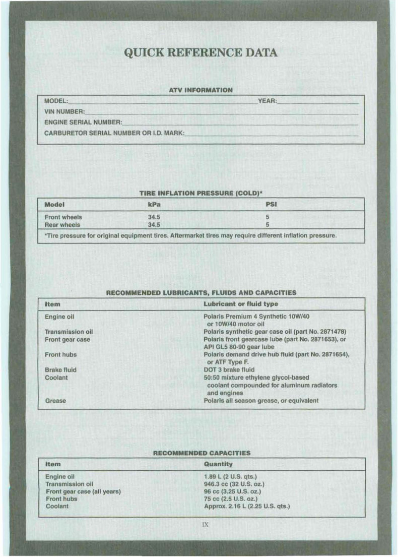
QUICK REFERENCE DATA ATV INFORMATION MODEL: YEAR: _ VIN NUMBER:, _ ENGINE SERIAL NUMBER : _ CARBURETOR SERIAL NUMBER OR 1 .0. MARK: _ TIRE INFLATION PRESSURE (COLD)' Model kPa PSI Front wheels 34.5 5 Rear wheels 34.5 5 "Tlre pressure for original equipment tires. Aftermarket tires may require different Inflation pressure. RECOMMENDED LUBRICANTS, FLUIDS AND CAPACITIES Item Engine 011 Transmission all Front gear case Front hubs Brake fluid Coolant Grease Item Engine all Transmission all Front gear case (all years) Front hubs Coolant Lubricant or fluid type Polaris Premium 4 Synthetic 10W/4Q or 10W/40 motor all Polaris synthetic gear case 011 (part No. 2871478) Polaris front gearcase lube (part No. 2871653), or API GL5 80·90 gear lube Polaris demand drive hub fluid (part No. 2871654), or ATF Type F. DOT 3 brake fluid 50:50 mixture ethylene glycol·based coolant compounded for aluminum radiators and engines Polaris all season grease, or equivalent RECOMMENDED CAPACITIES Quantity 1.89 L (2 U.S. qts.) 946.3 cc (32 U.S. oz.} 96 cc (3.25 U.S. oz.) 75 cc (2.5 U.S. oz.) Approx. 2.16 L (2.25 U.S. qts.) IX
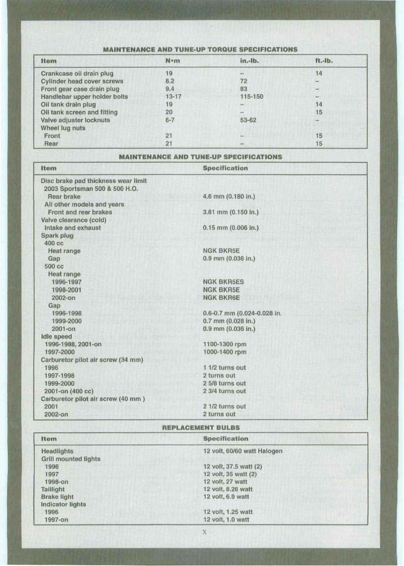
MAINTENANCE AND TUN E·UP TORQUE SPECIFICATIONS Item N'm in. .. lb. Crankcase oil drain plug 19 Cylinder head cover screws 8.2 72 Front gear case drain plug 9.4 83 Handlebar up per holder bol ts 13·17 115-150 Oil tank drain plug 19 0 11 tank screen and fitting 20 Valve adjuster locknuts 6-7 53-62 Whee/lug nuts Front 21 Rear 21 MAINTENANCEAND TUNE·UP SPECIFICATIONS ft .·lb. 14 14 15 15 15 Item Disc brake pad thickness wear limit 2003 Sportsman 500 & 500 H.O. Rear brake All other models and years Front and rear brakes Valve clearance (cold) Intake and exhaust Spark plug 400 cc Heat range Gap 500 ee Heat r ange 1996-1997 1998-2001 2002·on Gap 1996 · 1998 1999-2000 2001·on Idle sp eed 1996-1988, 2001-on 1997·2000 Carburetor pilot air screw (34 mm) 1996 1997·1998 1999-2000 2001 -on (400 ee) Carburetor pilot air screw (40 mm ) 2001 2002-on Item Headlights Grill mounted lights 1996 1997 1998-on Tai lli g ht Brake light Indicator lights 1996 1997-on Spec ificat ion 4.6 mm (0.180 In.) 3.81 mm (0.150 In.) 0.15 mm (0.006 In.) NGK BKR5E 0.9 mm (0.036 in.) NGK BKR5ES NGK BKR5E NGK BKR6E 0.6-0.7 mm (0.02 4-0.028 in . 0.7 mm (0.028 In.) 0.9 mm (0.036 in.) 1100-1300 rpm 1000-1400 rpm 1 1/2 turns out 2 turns out 2 5/8 turns out 23/4 turns out 2 1/2 turns out 2 turns out REPLACE MENT BULBS Spec ification 12 volt , 6 0/60 watt Halogen 12 volt, 37.5 watt (2) 12 volt, 35 watt (2) 12 volt, 27 watt 12 volt, 8.26 watt 12 volt, 6.9 watt 12 volt, 1.25 watt 12 volt ,l.0 watt x
CHAPTER ONE GENERAL INFORMATION This detailed. comprehensive manual covers the Polaris Sportsman 400, 500 and Xplorer 500 4 x 4 from I 996-on. Keep this book handy in the toolbox. Reading and using it will help to better understand how the vehi cle runs, lower repair costs and generally im- prove personal satisfaction with the vehicle. The following tables are included at the end of this chapter: Tah le 1 lists model year and number. Tahle 2 lists general dimensions. Ta ble 3 lists vehicle weight (dry) . Table 4 lists decimal and metric equivalents. Tab le 5 lists general torque specifications. Tab le 6 lists conversion tables . Ta ble 7 lists technical abbreviations. Table 8 lists metric tap and drill sizes. Tables 1-8 are at the end of this chapter. MANU AL OR GANIZATlO:'ll All dimensions and capacities are expresse d in English units familiar to U.S. mechanics. as well as in metric units. This chapter provides general information and discusses equipment and too ls useful both for pre- ventive maintenance and troubleshooting. Chapter Two provides methods and suggestions for the quick and accurate diagnosis and repair of problems. Troubles hooting procedures discuss typ-
2 ica l sy mpto ms and logi cal method s to pinpoint the t roub le. Chap ter Th ree explains all periodic lubrication and routine maintenance necessary to keep the veh i- cle funning well. Cha pter Three also includes rec- ommended t UIl C-Up proce du res , el imina ting the need to constantly consult chapters on the various ass e mb l ies . S ubsequen tc hapters describe specific sys te ms such as the engine, clutch/ drive belt system, trans- mission, exhaust, cooling, suspension and brakes. Eac hc hapter provides disass emb ly, repair and as- sembly procedures in a simple step- by-step form . Ifa repair is impract ica l for a ho me mechan ic . it is so indicated. It is usually faster ami less expensive to take such repairs to a dealer or competent repair shop. Specifications concerning a particular system arc i ncluded at the end of the appropriate chapter. So me of the proc edures in this manual spec ify s pec ial too ls. In most case s, the tool is illustrated ei- ther in actual use or alone. Well-equi pped mec han- ics may find they ca n substitute similar tools alre ady on hand or can fabricate thei r own . NOTES, CAUTIONS AND WARNI NGS T he terms NOT E, CAUTION and WAR NING have specific mean ings in this manual. A NOTE pro vides add itio na l inform ation to mak e a step or procedure easier or clearer . Di sregardi ng a NOTE cou ld cause incon venience, but wou ld not cause eq u ipment damage or personal injury. A CAUTION emp hasize, areas where eq uipment da mage co uld result. Di sregarding a CA UTION co uld cause permane nt mechanical dama ge ; hO\\I- eve r, personal inju ry is unlikely. A WARNING emphasizes areas where pe rsona l injury or eve n death could result from negligence. Mechanical damage may also occ ur. WARNI NG S are fa be taken seriously. In some cases, serious in- jut)' or death has resulted from dis regar ding similar w arn ings . SA rETY FIRST Professional mechan ics can work for years and never sustain a serious injury. I f a few rul es of com- mon sense and safe ty arc ob served. man y safe hours can be enjo yed servicing the ATY. Ignoring these CHAPTER ONE rules can injure so meo ne working on the vehicle. or damage the AT V. I. Never lise gaso line or any t ype of low flash po int solvent to clean parts, Sec Cleaning Parts and Han- dling Gasoline Safety in this chapter for additional informat ion on parts cleaning, gaso line usc and safety. NOTE The flash point is the lowest tempera- lur e at which the vapo rsfrom a com- bustible liquid will ign ite when in open ail: A lowjlash point solvent will ignite at a lower temperature than a higlzjlash point solvent. 2. Never smoke or usc a torch in the vicinity of flammable liquids in open containers , such as gas o- line or cleaning solvent. 3. lf wclding or brazing is req uir ed on the vehicle. remove the fuel rank, c arbur etor, and fron t and rea r shocks to a safe dist ance at leas t 50 feet (15 m) away. 4. Use the proper sized wrenches to avo id damage to fasteners. 5. When loosening a tight or stuck nut, be guided by what would h app en if the wrench slips. 6. When rep lacing a fastener, make sure to usc one with the same measurem ents and strength as the old one. Incorrect or mismatched fasteners can result in da mage to the vehicle and possibl e personal injury. Beware of fastener kits that are filled with cheap and p oor ly made nuts. bolts, was he rs and co tte r pins. Ref er to Faste ne rs in this chapter for addi- tional inform ation. 7. Keep all hand and power tool s in good condition. Wipe greasy and oily tools after using them. Dirty tools arc difficult to hold and can cause injury. Re- place or repair worn or damaged tools. 8. Kee p the work area clean and uncl uttered. 9. Wear safety g ogglcs during all operation s in- vo lving drillin g, grinding. the use of a cold chis el, usin g chemicals, cleaning parts, when u sing com- pressed air or anytim e the safety of eyes is in- vo lved. 10 . Mak e sure to wear the correct typ e of clothes for the jo b. Lon ghair should be tied up or covered with a cap so thai it cannot be caught by a piece of moving equipme nt or tool.
G ENE RAL INFO RMATION 11. Keep an approved fire extinguisher nearby. Be sure it is rated fur gasoline (Class B) and electrical (Cla ss C) fires. 12. When drying bearings or other rotating paris with compressed air, never allow the air j et to rotate the bearing or pari. The air jet is capab le of rotating them at speeds tar in excess of those for which they were designed . The bearing or rotating part is very likely to disintegrate and cause serious injury and damage. To prevent bearing damage when using com pressed air, hold the inner bearing race by hand. WARNING The improper use ofcompressed air is velJ' dangerous. Using compressed air to tlUSI off clothes, the ATV or workbench can cause jl ying particles to be blown into eyes or skill. Neve r direct or blow compress ed air in/a skin or through any bod y openin g (in- cluding cuts) as this can cause severe injury or death. Compressed air must be used care /id ly; never allow chil- dren to lise or play with a ll)' com- pressed air equipment or hoses. 13. Never work on the upper part of the vehicle while someone is worki ng underneath it. 14. When putting the vehicle on a stand, make sure the vehicle is secure before walking away from it. 15. Never carry sharp tools in clothing pockets. 16. There is always a right and wrong way to use tools. Learn to use them the right way. 17. Do not start and run the ATV in an enclosed area , The exhaust gases contain carbon monoxide, a colorless, odorless, poisonous gas. Carbon monox- ide levels build quickly in a small closed area and can cause unconsciousness and death in a short time. When it is necessary to start and run the vehi- cle during a service procedure, always do so out- side, or in a serv ice area equip ped with a ventilating system. CLEANING PARTS Cleaning parts is one of the more tedious and dif- ficu lt serv ice jo bs per formed in the home garage. While there are a nnmber of chemical cleaners and solvents available for home and shop lise, most arc poisonous and extremely flammable. To prevent chemical overexposure, vapor buildup, tire and sc- 3 rious injury. observe all manufact urer 's direct ions and warn ings while noting the following, I. Read the entire product label before using the chem ical. Observe the precautions and warnings on the label. Always know what type of chem ica l is be- ing used. 2. If the chemical product must be mixed, measure the proper amount according to the direction s. 3. Always provide sufficient ventilation when working with solvents or other chemicals. If a chemical can be smelled, there is some vapor in the air. The stronger the smell, the stronger the vapor con cent ration . 4. If a product is listed as combustible, flammable or an extremely flammable Iiquid, the danger offi re increases as the vapor collects and builds up in the shop. 5. lf a product is listed as a poison, the vapor is poi- sonous as well as the liquid. o. To prevent skin exposure, wear protective gloves when cleaning parts. Select a pair of chemi- cal-resistant gloves suitable for the type of cherni- cals that will be used. Replace the gloves whcn they become thin, damaged, cha nge COIOf, or swe ll. 7. Wear safety goggles when using chemicals and cleaning parts. 8. Do not lise more than one typ e of cleaning sol- vent at a lime. 9. If a pan must be heated to remove a bearing, clean it thoroughly to remove all oil, grease and cleaner residue. Then wash with soapy water and rinse with clear water, 10. Wear a respirator if the instruction label says to do so. II . Keep chemical products out of reach of chil- dren and pets. 12. To prevent sparks, usc a nylon bristle brush when cleaning paris. 13. When using a commercial paris washer, read and follow the manufacturer's instructions lor se- lecting the type of solvent to usc. Parts washers must be equipped with a fusible link designed to melt and drop the cover in the event of fire. 14. Wash both hands and arms thoroughly after cleaning parts, HANDLING GASOLINE SAFE LY Gasoline, a vola tile flammable liquid, is one of the most dan gerou s items in the shop, However, be- a
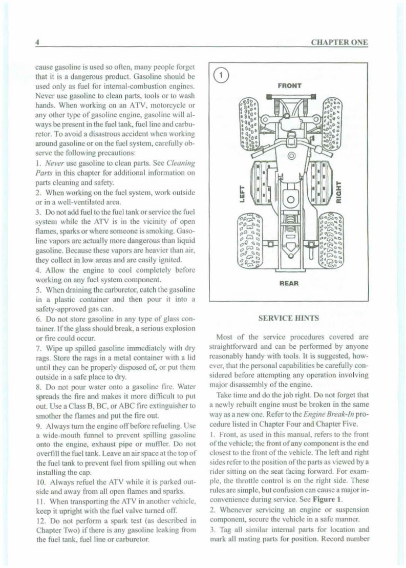
cause gasoline is used so often, manypeople forget that it is a dangerous product. Gasoline should be used only as fuel for internal-combustion engines. Never usc gas oline to clean part s, tools or to wash hands. When working on an ATV. motorcycle or any other type of gasoline engine. gasoline will al- ways be present in tbe fuel tank, fuel line and carbu- retor. To avoid a disa strous accident when working around gasoline or on the fuel system, carefully ob- serve the following precauti ons: I. Never usc gasoline to clean part s. See Cleaning Part s in this chapterfor additional information on pans cleaning and safety. 2. Wh en working on the fuel sys tem, work outside or in a well-ven tilated area. 3. Do not add fuel to the fuel tank or service the fuel system while the ATV is in the vicinity of open flames, sparksor where someoneissmoking. Gaso- line vapors arc actually more dangerous than liquid gasoline. Because these vapors are heavier than air. they collect in low areas and are easily ignited. 4. Allow the engine to coo l completely bef ore working on any fuel system component. 5. When draining the carburetor, catch the gasoline in a plastic container and then pour it into a safety-approved gas can. 6. Do not store gasoline in any type of glass con- tainer. If the glass shoold break . a serious explosion or fire could occur. 7. Wipe up spilled gasoline immediately with dry rags. Store the rags in a metal container with a lid ontil they can be properly disposed of . or put them outside in a safe place to dry. 8. Do not po ur water onto a gasoline tire. Water spreads the lire and makes it more difficult to put oot. Use a Class B. BC. or AIlC fire extinguisher to smother the names and put the fire out. 9. Always tum the engine off before refu eling. Usc a wide-mouth funnel to prevent spilling gasoline onto the engine. exhaust pipe or muffl er. Do not overfill the fuel tank . Leave an airspace at the topof the fuel tank to prevent fuel from spilling out when installing the cap. 10. Always refuel the ATV while it is parked out- side and away fro m all open flames and sparks. II . When transporting the ATV in another vehicle. keep it upright with the fuel valve turned oiT. 12. Do not perform a spark test (as described in Chapter Two ) if there is any gasoline leaking from the fuel tank , fuel line or carburetor. CIIAI'TER O~E FRONT REAR SERVICE HINTS ~..Iost of the service procedures covered are straightfor wa rd and can be performed by anyone reasonably handy with tools. It is suggested. how- eve r. that the personal capabilities be carefully eon- sidercd before attemp ting any operation involving major disassembly of the engine. Take time and do the job right. Do not forget that a newly rebuilt engine must be broken in the same wayas a new one. Refer to the Engine Br eak-In pro- ccdure listed in Chapter Four and Chapter Five. J. Fron t, as used in this manual, refersto the fro nt ofthe vehicle; the front of any component is the end closest to the front of the vehicle. The left and right sides refer to the position afthe p art s as viewed by a rider sitting 011 the seat rac ing forward. For exam- ple, the throttle control is on the right side. The se rules aresimple. but confusion can cause a major in- convenience during service. Sec Figure 1. 2. Whenever servicing an engine or suspens ion component, secure the vehicle in a safe manner. 3. Tag all similar internal part s for location and mark all mating part s for position. Record number
Upon purchasing this manual, you will receive a .PDF file containing an email contact. After contacting us, you will receive a reply with a link to access the manual for your Polaris Sportsman 500 1996-1998.
This comprehensive manual covers every nut and bolt on your machine. With hundreds of pages, it provides detailed guidance on identifying and resolving various issues, from routine maintenance like oil changes to more complex tasks such as transmission swaps. The manual includes numerous illustrations to assist you and features easy-to-understand text throughout.
Utilize the search function to navigate the manual efficiently and print the necessary pages. This Factory Service Repair Manual offers a step-by-step guide to equip you with the essential knowledge for maintenance and repairs, mirroring the expertise of factory-trained technicians.
By leveraging the insights provided in this service repair manual, any owner can confidently make informed decisions regarding the upkeep and repair of their machine.
Rest assured, in addition to the high-quality service manual, we are committed to delivering exceptional customer service, ensuring your satisfaction.
Recently Viewed
5,521,897Happy Clients
2,594,462eManuals
1,120,453Trusted Sellers
15Years in Business
Price:
Actual Price:
1996-1998 Polaris Sportsman 500 Service & Repair Manual