1996-2006 Polaris Sportsman 500 DUSE HO Service & Repair Manual
What's Included?
Lifetime Access
Fast Download Speeds
Online & Offline Access
Access PDF Contents & Bookmarks
Full Search Facility
Print one or all pages of your manual
2 CHAPTER ONE SAFETY Professional mechanics can work for years and never sustain a serious injury or mishap. Follow these guidelines and practice common sense to safely service the ATV. 1. Do not operate the ATV in an enclosed area. The ex- haust gasses contain carbon monoxide, an odorless, color- less and tasteless poisonous gas. Carbon monoxide levels build quickly in small enclosed areas and can cause uncon- sciousness and death in a short time. Make sure to properly ventilate the work area or operate the ATV outside. 2. Never use gasoline or any extremely flammable liq- uid to clean parts. Refer to Cleaning Parts and Handling Gasoline Safely in this section. 3. Never smoke or use a torch in the vicinity of flammable liquids, such as gasoline or cleaning solvent. 4. Do not remove the radiator cap or cooling system hose when the engine is hot. The cooling system is pressurized and the high temperature coolant may cause injury. 5. Dispose and store coolant in a safe manner. Do not al- low children or pets access to open containers of coolant. Animals are attracted to antifreeze coolant. 6. Avoid contact with engine oil and other chemicals. Most are known carcinogens. Wash hands thoroughly after com- ing in contact with engine oil. If possible, wear a pair of disposable gloves. 7. If welding or brazing on the ATV, remove the fuel tank to a safe distance at least 50 ft. (15 m) away. 8. Use the correct type and size of tools to avoid damaging fasteners. 9. Keep tools clean and in good condition. Replace or re- pair worn or damaged equipment. 10. When loosening a tight fastener, be guided by what would happen if the tool slips. 11. When replacing fasteners, make sure the new fasteners are the same size and strength as the original ones. 12. Keep the work area clean and organized. 13. Wear eye protection any time the safety of the eyes is in question. This includes procedures that involve drilling, grinding, hammering, compressed air and chemicals. 14. Wear the correct clothing for the job. Tie up or cover long hair so it does not get caught in moving equipment. 15. Do not carry sharp tools in clothing pockets. 16. Always have an approved fire extinguisher available. Make sure it is rated for gasoline (Class B) and electrical (Class C) fires. 17. Do not use compressed air to clean clothes, the ATV or the work area. Debris may be blown into the eyes or skin. Never direct a compressed air hose at anyone. Do not al- low children to use or play with any compressed air equip- ment. 18. When using compressed air to dry rotating parts, hold the part so it does not rotate. Do not allow the force of the air to spin the part. The air jet is capable of rotating parts at extreme speed. The part may disintegrate or become dam- aged, causing serious injury. 19. Do not inhale the dust created by brake pad and clutch wear. These particles may contain asbestos. In addition, some types of insulating materials and gaskets may con- tain asbestos. Inhaling asbestos particles is hazardous to health. 20. Never work on the ATV while someone is working under it. 21. When placing the ATV on a stand, make sure it is se- cure before walking away. Handling Gasoline Safely Gasoline is a volatile flammable liquid and is one of the most dangerous items in the shop. Because gasoline is used so often, many people forget it is hazardous. Only use gasoline as fuel for gasoline internal combustion engines. Keep in mind when working on the machine, gasoline is always present in the fuel tank, fuel line and throttle body. To avoid a disastrous accident when working around the fuel system, carefully observe the following precautions: 1. Never use gasoline to clean parts. Refer to Cleaning Parts in this section. 2. When working on the fuel system, work outside or in a well-ventilated area. 3. Do not add fuel to the fuel tank or service the fuel sys- tem while the ATV is near open flames, sparks or where someone is smoking. Gasoline vapor is heavier than air; it collects in low areas and is more easily ignited than liquid gasoline. 2 1
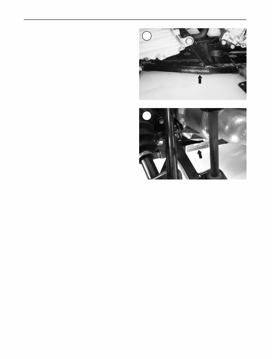
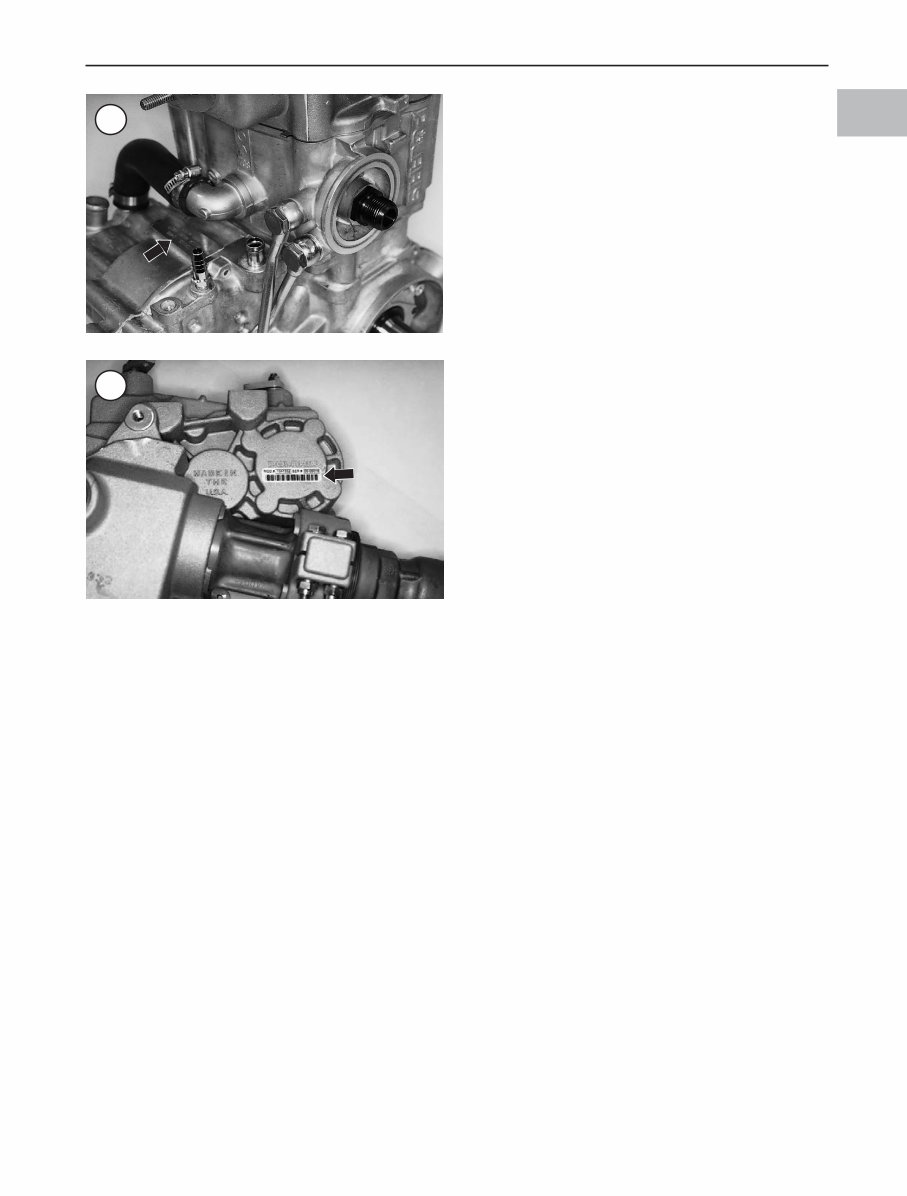
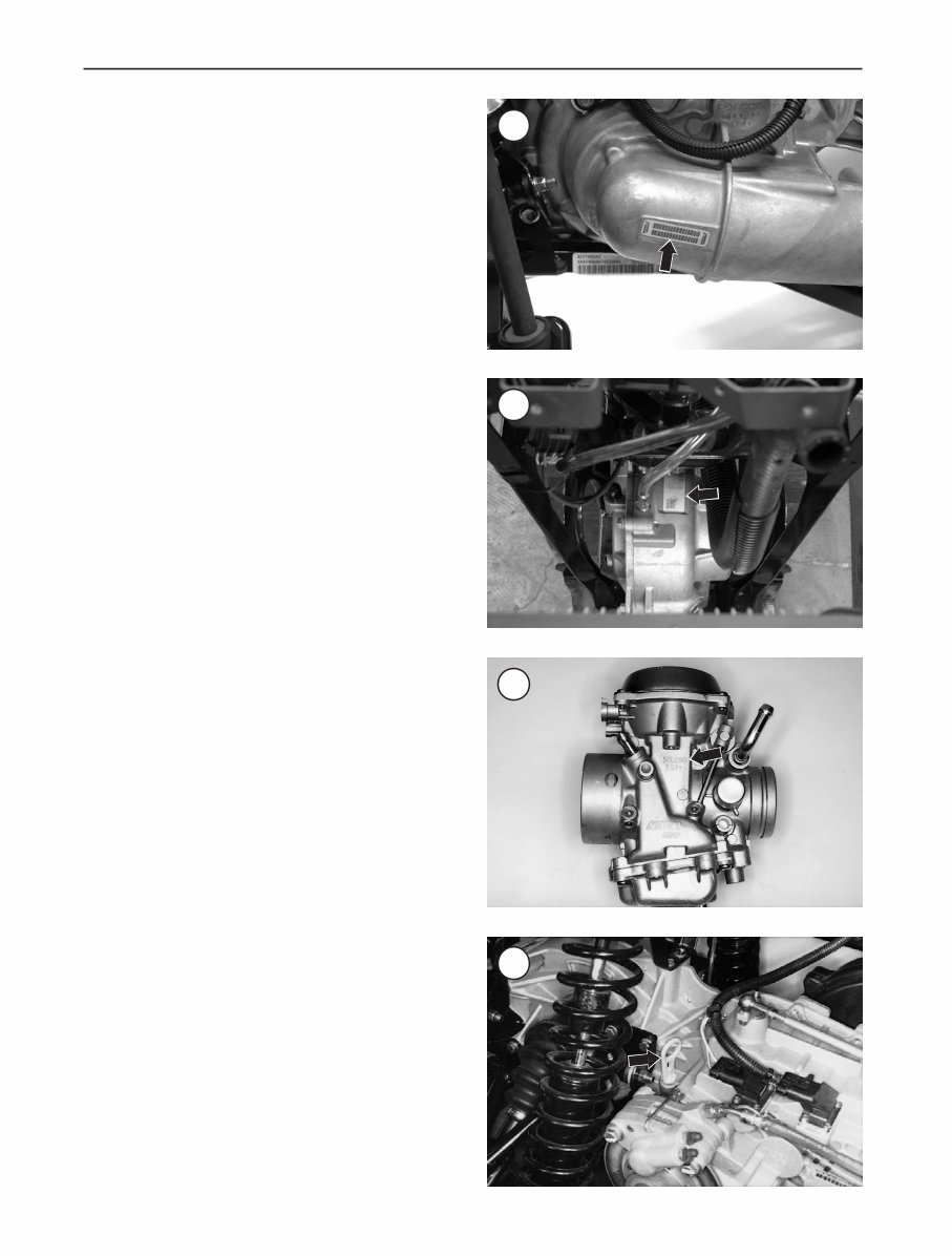
GENERAL INFORMATIO 3 1 4. Allow the engine to cool completely before working on any fuel system component. 5. Do not store gasoline in glass containers. If the glass breaks, a serious explosion or fire may occur. 6. Immediately wipe up spilled gasoline with rags. Store the rags in a metal container with a lid until they can be properly disposed of, or place them outside in a safe place for the fuel to evaporate. 7. Do not pour water onto a gasoline fire. Water spreads the fire and makes it more difficult to put out. Use a class B, BC or ABC fire extinguisher to extinguish the fire. 8. Always turn off the engine before refueling. Do not spill fuel onto the engine or exhaust system. Do not overfill the fuel tank. Leave an air space at the top of the tank to al- low room for the fuel to expand due to temperature fluctua- tions. Cleaning Parts Cleaning parts is one of the more tedious and difficult service jobs performed in the home garage. Many types of chemical cleaners and solvents are available for shop use. Most are poisonous and extremely flammable. To prevent chemical exposure, vapor buildup, fire and serious injury, observe each product warning label and note the follow- ing: 1. Read and observe the entire product label before using any chemical. Always know what type of chemical is being used and whether it is poisonous and/or flammable. 2. Do not use more than one type of cleaning solvent at a time. If mixing chemicals is required, measure the proper amounts according to the manufacturer. 3. Work in a well-ventilated area. 4. Wear chemical-resistant gloves. 5. Wear safety glasses. 6. Wear a vapor respirator if the instructions call for it. 7. Wash hands and arms thoroughly after cleaning parts. 8. Keep chemical products away from children and pets. 9. Thoroughly clean all oil, grease and cleaner residue from any part that must be heated. 10. Use a nylon brush when cleaning parts. Metal brushes may cause a spark. 11. When using a parts washer, only use the solvent recom- mended by the manufacturer. Make sure the parts washer is equipped with a metal lid that will lower in case of fire. Warning Labels Most manufacturers attach information and warning la- bels to the ATV. These labels contain instructions that are important to personal safety when operating, servicing, transporting and storing the ATV. Refer to the owner’s manual for the description and location of labels. Order re- placement labels from the manufacturer if they are missing or damaged. SERIAL NUMBERS Serial numbers are stamped on various locations on the frame, engine, transmission and carburetor. Record these numbers in the Quick Reference Data section in the front of the manual. Have these numbers available when order- ing parts. The frame number label (Figure 1) is located on the left side lower frame tube near the rear portion of the front A-arm mount. On some models, a decal with the VIN number (Figure 2) is located on the right side of the frame below the trans- mission. The engine serial number (Figure 3) is stamped on the raised pad on the center top of the crankcase beneath the cylinder coolant elbow. The transmission serial number is located on top of the transmission case below the shift bell crank and on a label on the right side (Figure 4) or on the side of the snorkel gear housing (Figure 5). The front drive gearcase serial number (Figure 6, typi- cal) is located on top of the unit. The carburetor serial number (Figure 7) is located on the left side of the carburetor body. 3 4
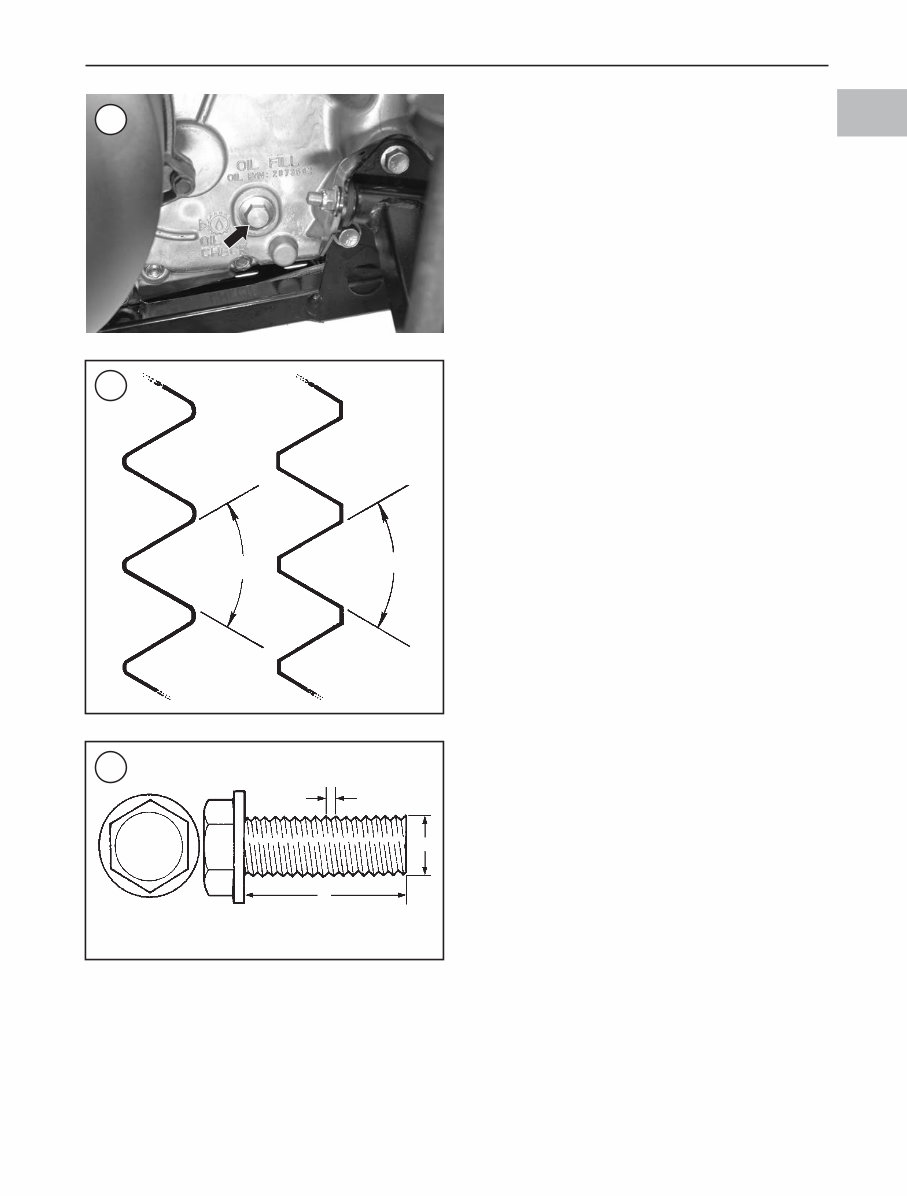
4 CHAPTER ONE MODEL IDENTIFICATION (2004 MODELS) Two versions of Sportsman 400 and 500 were produced in 2004. Always refer to the designation of Early 2004 or Late 2004 in the text and tables throughout the manual. 1. Transmission. On early 2004 models, the oil level is checked with a dipstick (Figure 8); on late 2004 models, the oil level is checked with oil fill bolt (Figure 9) on the left side of the case. The gear shifter on early 2004 is on a straight line from High to Park, on late 2004 the shift pat- tern is in an H pattern with the Low gear on the right side of the H and High to Reverse in a straight line on the left side, 2. Speedometer display. The speedometer display in late 2004 models includes a fuel level indicator light. This light is not found on early 2004 models. 3. Two different ignition systems are used on these models and are identified in Chapter Thirteen. 4. Additional differences occur with the front drive unit and front hubs as described in the various chapters. FASTENERS WARNING Do not install fasteners with a strength clas- sification lower than what was originally installed by the manufacturer. Doing so may cause equipment failure and/or damage. Threaded Fasteners Threaded fasteners secure most of the components on the ATV. Most fasteners are tightened by turning them clockwise (right-hand threads). If the normal rotation of the component being tightened would loosen the fastener, it may have left-hand threads. If a left-hand threaded fas- tener is used, it is noted in the text. Two dimensions are required to match the thread size of the fastener: the number of threads in a given distance and the outside diameter of the threads. The two systems currently used to specify threaded fastener dimensions are the U.S. standard system and the metric system (Figure 10). Pay particular attention when working with unidentified fasteners; mismatching thread types can damage threads. Both American and Metric fas- teners are used on the ATV. To ensure that the fastener threads are not mismatched or cross-threaded, start all fasteners by hand. If a fastener is hard to start or turn, determine the cause before tightening with a wrench. Match the length (L, Figure 11), diameter (D) and dis- tance between thread crests (pitch) (T) classify metric screws and bolts. A typical bolt may be identified by the numbers, 8-1.25 × 130. This indicates the bolt has a diam- eter of 8 mm, the distance between thread crests is 1.25 mm and the length is 130 mm. Always measure bolt length 6 7 5 8
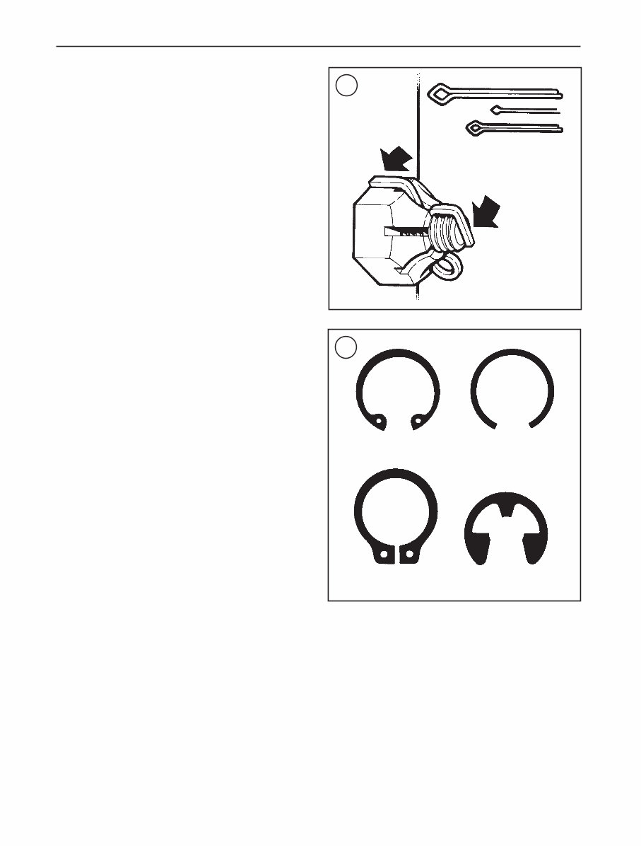
GENERAL INFORMATIO 5 1 as shown in L, Figure 11 to avoid purchasing replacements of the wrong length. If a number is located on the top of a metric fastener (Figure 11) indicate the strength. The stronger the fastener will have a higher number. Typically, unnumbered fasten- ers are the weakest. Many screws, bolts and studs are combined with nuts to secure particular components. To indicate the size of a nut, manufacturers specify the internal diameter and the thread pitch. The measurement across two flats on a nut or bolt indi- cates the wrench size. Torque Specifications The materials used in the manufacturing of the ATV may be subjected to uneven stresses if the fasteners of the vari- ous subassemblies are not installed and tightened correctly. Improperly installed fasteners or ones that worked loose can cause extensive damage. It is essential to use an accu- rate torque wrench as described in this chapter. Specifications for torque are provided in Newton-meters (N•m), foot-pounds (ft.-lb.) and inch-pounds (in.-lb.). Refer to Table 5 for general torque specifications. To use Table 5, first determine the size of the fastener as described in Threaded Fasteners in this section. Torque specifications for specific components are at the end of the appropriate chapters. Torque wrenches are covered in Tools in this chapter. Self-Locking Fasteners Several types of bolts, screws and nuts incorporate a system that creates interference between the two fasteners. Interference is achieved in various ways. The most com- mon types are the nylon insert nut and a dry adhesive coat- ing on the threads of a bolt. Self-locking fasteners offer greater holding strength than standard fasteners, which improves their resistance to vi- bration. All self-locking fasteners cannot be reused. The materials used to form the lock become distorted after the initial installation and removal. Discard and replace self- locking fasteners after removing them. Do not replace self- locking fasteners with standard fasteners. Washers The two basic types of washers are flat washers and lock- washers. Flat washers are simple discs with a hole to fit a screw or bolt. Lockwashers are used to prevent a fastener from working loose. Washers can be used as spacers and seals, or can help distribute fastener load and prevent the fastener from damaging the component. As with fasteners, when replacing washers make sure the replacement washers are of the same design and quality. Cotter Pins A cotter pin is a split metal pin inserted into a hole or slot to prevent a fastener from loosening. In certain applica- tions, such as the rear axle, the fastener must be secured in this way. For these applications, a cotter pin and castellated (slotted) nut is used. To use a cotter pin, first make sure the diameter is correct for the hole in the fastener. After correctly tightening the 10 11 9 U.S. Standard Metric 60° 60° –9.8 Grade marking L D t
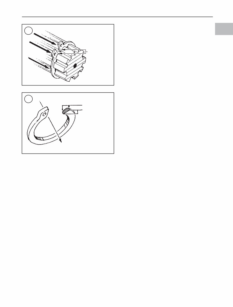
6 CHAPTER ONE fastener and aligning the holes, insert the cotter pin through the hole and bend the ends over the fastener (Figure 12). Unless instructed to do so, never loosen a tightened fas- tener to align the holes. If the holes do not align, tighten the fastener enough to achieve alignment. Cotter pins are available in various diameters and lengths. Measure the length from the bottom of the head to the tip of the shortest pin. Snap Rings and E-clips Snap rings (Figure 13) are circular-shaped metal retain- ing clips. They are required to secure parts and gears in place on parts such as shafts, pins or rods. External type snap rings are used to retain items on shafts. Internal type snap rings secure parts within housing bores. In some ap- plications, in addition to securing the component(s), snap rings of varying thickness also determine endplay. These are usually called selective snap rings. The two basic types of snap rings are machined and stamped snap rings. Machined snap rings (Figure 14) can be installed in either direction, because both faces have sharp edges. Stamped snap rings (Figure 15) are manu- factured with a sharp and a round edge. When installing a stamped snap ring in a thrust application, install the sharp edge facing away from the part producing the thrust. E-clips are used when it is not practical to use a snap ring. Remove E-clips with a flat blade screwdriver by pry- ing between the shaft and E-clip. To install an E-clip, cen- ter it over the shaft groove and push or tap it into place. Observe the following when installing snap rings: 1. Remove and install snap rings with snap ring pliers. Refer to Tools in this chapter. 2. In some applications, it may be necessary to replace snap rings after removing them. 3. Compress or expand snap rings only enough to install them. If overly expanded, they lose their retaining ability. 4. After installing a snap ring, make sure it seats com- pletely. 5. Wear eye protection when removing and installing snap rings. SHOP SUPPLIES Lubricants and Fluids Periodic lubrication helps ensure a long service life for any type of equipment. Using the correct type of lubricant is as important as performing the lubrication service, al- though in an emergency the wrong type is better than not using one. The following section describes the types of lubricants most often required. Make sure to follow the manufacturer’s recommendations for lubricant types. Engine oils Engine oil for four-stroke ATV engine use is classified by three standards: the American Petroleum Institute (API) service classification, the Society of Automotive Engineers (SAE) viscosity rating and the Japanese Automobile Standards Organization (JASO) T 903 Standard rating. The API and SAE information is on all oil container la- bels. The JASO information is found on oil containers sold by the oil manufacturer specifically for motorcycle and ATV use. Two letters indicate the API service classification. The number or sequence of numbers and letter (10W-40 for example) is the oil’s viscosity rating. The API service classification and the SAE viscosity index are not indica- 12 13 correct installation of cotter pin Internal snap ring external snap ring plain circlip e-clip
GENERAL INFORMATIO 7 1 tions of oil quality. The JASO certification label identifies two separate oil classifications and a registration number to ensure the oil has passed all JASO certification standards for use in four-stroke motorcycle and ATV engines. The API service classification indicates that the oil meets specific lubrication standards and is not a indication of oil quality. Do not use automotive oil with an SJ or higher classification. They are designed for automotive applica- tions and contain friction modifiers that reduce frictional losses. Specifically designed for automotive engines, oils with this classification can cause engine wear. The first let- ter in the classification S indicates that the oil is for gaso- line engines. The second letter indicates the standard the oil satisfies. The JASO certification label identifies two separate oil classifications and a registration number to ensure the oil has passed all JASO certification standards for use in four- stroke motorcycle and ATV engines. The classifications are: MA (high friction applications) and MB (low friction applications). Viscosity is an indication of the oil’s thickness. Thin oils have a lower number while thick oils have a higher number. Engine oils fall into the 5- to 50-weight range for single-grade oils. Most manufacturers recommend multi-grade oil. These oils perform efficiently across a wide range of operating conditions. Multi-grade oils are identified by a W after the first number, which indicates the low-temperature viscos- ity. Engine oils are most commonly mineral (petroleum) based, however, synthetic and semi-synthetic types are used more frequently. Always use oil with the classifica- tion recommended by the manufacturer (Chapter Three). Using oil with a different classification can cause engine damage. Greases Grease is lubricating oil with thickening agents added to it. The National Lubricating Grease Institute (NLGI) grades grease. Grades range from No. 000 to No. 6, with No. 6 being the thickest. Typical multipurpose grease is NLGI No. 2. For specific applications, manufacturers may recommend water-resistant type grease or one with an ad- ditive such as molybdenum disulfide (MoS 2 ). Brake fluid Brake fluid is the hydraulic fluid used to transmit hy- draulic pressure (force) to the wheel brakes. Brake fluid is classified by the Department of Transportation (DOT). Current designations for brake fluid are DOT 3, DOT 4 and DOT 5. This classification appears on the fluid container. The models covered in the manual require DOT 4. Each type of brake fluid has its own definite characteris- tics. Do not intermix different brake fluid; this may cause brake failure. DOT 5 is a silicone-based. DOT is not com- patible with other brake fluids or in systems for which it was not designed. Mixing DOT 5 fluid with other fluids may cause brake system failure. When adding brake fluid, only use DOT 4 brake fluid. Brake fluid will damage any plastic, painted or plated surface it contacts. Use extreme care when working with brake fluid and remove any spills immediately with soap and water. Hydraulic brake systems require clean and moisture free brake fluid. Never reuse brake fluid. Keep containers and reservoirs properly sealed. Coolant Coolant is a mixture of water and antifreeze used to dis- sipate engine heat. Ethylene glycol is the most common form of antifreeze used. Check with the ATV manufac- turer’s recommendations (Chapter Three) when selecting antifreeze. Most require one specifically for use in alumi- num engines. These types of antifreeze have additives that inhibit corrosion. Only mix distilled water with antifreeze. Impurities in tap water may damage internal cooling system passages. 14 15 Direction of thrust Full support areas rounded edges Sharp edges Direction of thrust
This is a comprehensive service repair manual package for the Polaris Sportsman 500 + DUSE + HO H.O spanning the years 1996-2006. It includes four manuals in the package.
Additional specific year manuals for this model are available for the following:
There is no shipping involved, and you can access the manuals instantly. These are the same manuals used by motorcycle dealerships for bike repairs. The topics covered include Engine, General Information, Transmission, Chassis, Lighting, Steering, Seats System, Clutch, Suspension, Locks, Brakes, Lubrication, Electrical, Frame Fuel System, Battery, and more.
These manuals are in Adobe Acrobat format and are compatible with both PC and Mac. You can print out the specific section you need and discard it after use, or print the entire manual and store it in a 3-ring binder for reference.
Instant delivery ensures no waiting for a CD to arrive via mail. Please note that high-speed internet connection is recommended, as some files may be too large for dial-up users.
Get your manual now and have the necessary information at your fingertips for your repair needs.
Recently Viewed
5,521,897Happy Clients
2,594,462eManuals
1,120,453Trusted Sellers
15Years in Business
Price:
Actual Price:
1996-2006 Polaris Sportsman 500 DUSE HO Service & Repair Manual