PRAIRIE 400 4X4 Kawasaki PRAIRIE 400 All Terrain Vehicle Service Manual
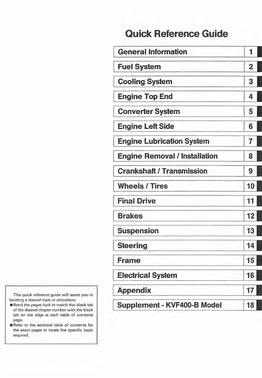
This quick reference guide will assist you in locat ing a desired topic or procedure. • Bend the pages back to match the black tab of the desired chapter number with the black tab on the edge at each table of contents page . • Refer to the sectional table of co ntents for the exact pages to locate the specific topic required . I I I I I I I I I I I 1 I Quick Reference Guide General Information Fuel System Cooling System Engine Top End Converter System Engine Left Side Engine Lubrication System Engine Removal/Installation Crankshaft I Transmission Wheels I Tires Final Drive Brakes Suspension Steering Frame Electrical System Appendix Supplement - KVF400-B Model 1 I 2 I 3 I 4 I 5 I 6 I 7 I 8 I 9 I 10 I 111 121 131 1 141 1 151 1 16 1 1 171 1 1 81
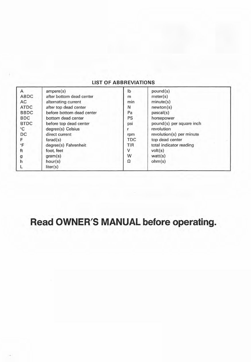
LIST OF ABBREVIATIONS A ampere(s) Ib pound(s) ABDC after bottom dead center m meter(s) AC alternating current min minute(s) ATDC after top dead center N newton(s) BBDC before bottom dead center Pa pascal(s) BDC bottom dead center PS horsepower BTDC before top dead center psi pound(s) per square inch °C degree(s) Celsius r revolution DC direct current rpm revolution(s) per minute F farad(s) TDC top dead center of degree (s) Fahrenheit TIR total indicator reading ft foot, feet V volt(s) g gram(s) W watt(s) h hour(s) Q ohm(s) L liter(s) Read OWNER'S MANUAL before operating.
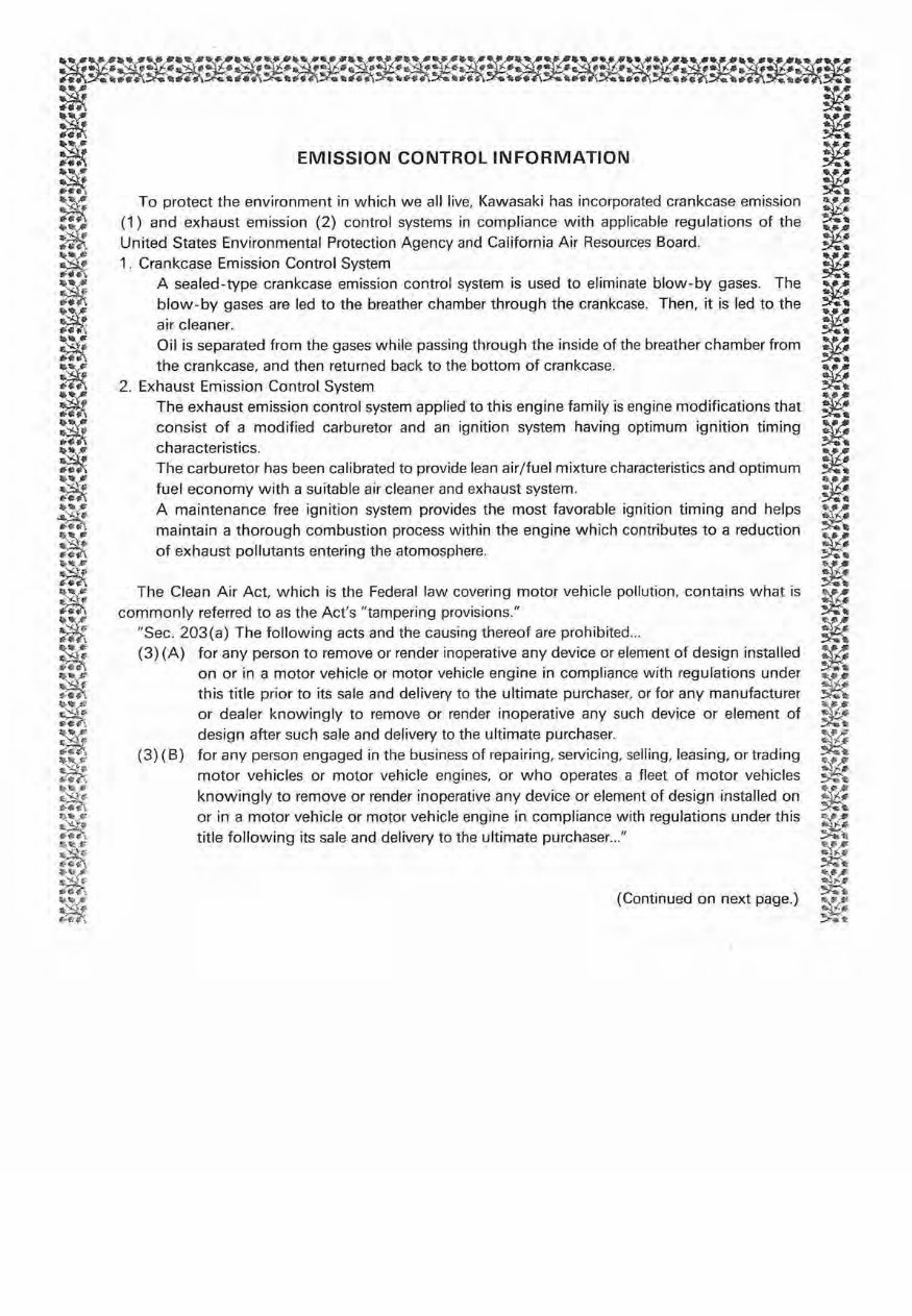
~~~~~~~~~~~~~~~~~~~~~~~~~~~~ m~ .. m~"".~~"'.7\>.....m~".f?\,.';\,~~,~~~ .. m~;m~m*.~~m~m~ ~ ~ ~ ~ ~ EMISSION CONTROL INFORMATION ~ ~ ~ ~ ~ ~ To protect the environment in which we all live, Kawasaki has incorporated crankcase emission :r~ (1) and exhaust emission (2) control systems in compliance with applicable regulations of the ~ ~ ~ ~ ~.n~~adn~~:::s EE~~:~~nm~:~~~~r~::~~: Agency and California Air Resources Board. ~ II(~ A sealed-type crankcase emission control system is used to eliminate blow-by gases. The !f..:! ~ blow-by gases are led to the breather chamber through the crankcase. Then, it is led to the ~ ~ air cleaner. ~ ~ Oil is separated from the gases while passing through the inside of the breather chamber from ~ :~: the crankcase, and then returned back to the bottom of crankcase. :f~ irn\ 2. Exhaust Emission Control System ~ ~ .. ~ .. - m The exhaust emission control system applied to this engine family is engine modifications that ~ ~ consist of a modified carburetor and an ignition system having optimum ignition timing W .. 71 ~_ !~-t. characteristics. :r..:: m The carburetor has been calibrated to provide lean air/fuel mixture characteristics and optimum ~ !¥ fuel economy with a suitable air cleaner and exhaust system. :r~ ~~ .~ ~ ~a:~~~~e:~~~~O~eg~ ~gon!~ounst~~~tep:::~v~~~i~h:h:~~9t i~::~~~~ ~gon~~~~~u:~~~~ga ar:~u~~il~~ ~ ~ ~ :'¢l\ of exhaust pollutants entering the atomosphere. > .. " ~~# !~..:! ~ >~ ~ The Clean Air Act, which is the Federal law covering motor vehicle pollution, contains what is ~ ~ ." commonly referred to as the Act's "tampering provisions." ~ ifn, "Sec . 203(a) The following acts and the causing thereof are prohibited ... ~ ~ (3) (A) for any person to remove or render inoperative any device or element of design installed :r~ :>ffi ~ :~ on or in a motor vehicle or motor vehicle engine in compliance with regulations under !; .... " ~Th this title prior to its sale and delivery to the ultimate purchaser, or for any manufacturer ~ /k..... "'JI-,$' ~ or dealer knowingly to remove or render inoperative any such device or element of ~ ~ design after such sale and delivery to the ultimate purchaser. ~ (3) (8) for any person engaged in the business of repairing, servicing, selling, leasing, or trading ~ ~. (/.fl'l motor vehicles or motor vehicle engines. or who operates a fleet of motor vehicles ~ ~: knowingly to remove or render inoperative any device or element of design installed on !t6% eril'i!'. ~lI. o;; . ... . ¢' or in a motor vehicle or motor vehicle engine in compliance with regulations under this ~¥,. ~ title following its sale and delivery to the ultimate pu,chase, .. " ~ 1);.0 , 1" "".~ ~f- ~~~ t1i¢*I ~ ,.~ ., (Continued on next page.) "N' 6t 1I':'Jf' ~'" ,,:~ :;:.;; \t
NOTE o The phrase "remove or render inoperative any device or element of design" has been generally interpreted as follows : 1. Tampering does not include the temporary removal or rendering inoperative of devices or elements of design in order to perform maintenance. 2. Tampering could include: a. Maladjustment of vehicle components such that the emission standards are exceeded. b. Use of replacement parts or accessories which adversely affect the performance or durability of the motorcycle. c. Addition of components or accessories that result in the vehicle exceeding the standards. d. Permanently removing, disconnecting, or rendering inoperative any component or element of design of the emission control systems. WE RECOMMEND THAT ALL DEALERS OBSERVE THESE PROVISIONS OF FEDERAL LAW, THE VIOLATION OF WHICH IS PUNISHABLE BY CIVIL PENALTIES NOT EXCEEDING $10,000 PER VIOLATION. (US Model only) To minimize the noise emissions from this product, Kawasaki has equipped it with effective intake and exhaust silencing systems. They are designed to give optimum performance while maintaining a low noise level. Please do not remove these systems, or alter them in any which results in an increase in noise level.
Foreword This manual is designed primarily for use by trained mechanics in a properly equipped shop. However, it contains enough detail and basic information to make it useful to the owner who desires to perform his own basic maintenance and repair work. A basic knowledge of mechanics, the proper use of tools, and workshop procedures must be understood in order to carry out maintenance and repair satisfactorily. Whenever the owner has insufficient experience or doubts his ability to do the work, all adjustments, maintenance, and repair should be carried out only by qualified mechanics. In order to perform the work efficiently and to avoid costly mistakes, read the text, thoroughly familiarize yourself with the procedures before starting work, and then do the work carefully in a clean area . Whenever special tools or equipment are specified, do not use makeshift tools or equipment . Precision measurements can only be made if the proper instruments are used, and the use of substi- tute tools may adversely affect safe operation. For the duration of the warranty period, we recommend that all repairs and scheduled maintenance be performed in accordance with this service manual. Any owner maintenance or repair procedure not performed in accordance with this manual may void the warranty. To get the longest life out of your Vehicle: .Follow the Periodic Maintenance Chart in the Service Manual. • Be alert for problems and non-scheduled mainte- nance . • Use proper tools and genuine Kawasaki vehicle parts. Special tools, gauges, and testers that are necessary when servicing Kawasaki vehicles are introduced by the Special Tool Catalog or Manual. Genuine parts provided as spare parts are listed in the Parts Catalog. • Follow the procedures in this manual carefully. Don't take shortcuts. • Remember to keep complete records of mainte- nance and repair with dates and any new parts installed. How to Use this Manual In preparing this manual, we divided the product into its major systems. These systems became the manual's chapters. All information for a particular system from adjustment through disassembly and inspection is located in a single chapter. The Quick Reference Guide shows you all of the product's system and assists in locating their chapters. Each chapter in turn has its own compre- hensive Table of Contents. The Periodic Maintenance Chart is located in the General Information chapter. The chart gives a time schedule for required maintenance operations. If you want spark plug information, for example, go to the Periodic Maintenance Chart first. The chart tells you how frequently to clean and gap the plug. Next, use the Quick Reference Guide to locate the Electrical System chapter. Then, use the Table of Contents on the first page of the chapter to find the Spark Plug section. Whenever you see these WARNING and CAUTION symbols, heed their instructions! Always follow safe operating and maintenance practices. AWARNING This warning symbol identifies special instructions or procedures which, if not correctly followed, could result in personal injury, or loss of life. CAUTION This caution symbol identifies special instructions or procedures which, if not strictly observed, could result in damage to or destruction of equipment.
This manual contains four more symbols (in addition to WARNING and CAUTION) which will help you distinguish different types of information. NOTE o This note symbol indicates points of partic- ular interest for more efficient and convenient operation . • Indicates a procedural step or work to be done. o Indicates a procedural sub-step or how to do the work of the procedural step it follows. It also precedes the text of a NOTE. * Indicates a conditional step or what action to take based on the results of the test or inspection in the procedural step or sub-step it follows. In most chapters an exploded view illustration of the system components follows the Table of Contents. In these illustrations you will find the instructions indicating which parts require specified tightening torque, oil, grease or a locking agent during assembly.
1-2 GENERAL INFORMATION Before Servicing Before starting to service a vehicle, careful reading of the applicable section is recommended to eliminate unnecessary work. Photographs, diagrams, notes, cautions, warnings, and detailed descriptions have been included wherever necessary. Nevertheless, even a detailed account has limitations, a certain amount of basic knowledge is also required for successful work. Especially note the following: (1) Dirt Before removal and disassembly, clean the vehicle. Any dirt entering the engine or other parts will work as an abrasive and shorten the life of the vehicle. For the same reason, before installing a new part, clean off any dust or metal filings. (2) BatteryGround Remove the ground (-) lead from the battery before performing any disassembly operations on the vehicle. This prevents: (a) the possibility of accidentally turning the engine over while partially disassembled. (b) sparks at electrical connections which will occur when they are disconnected. (c) damage to electrical parts. (3) Installation, Assembly Generally, installation or assembly is the reverse of removal or disassembly. But if this Service Manual has installation or assembly procedures, follow them. (4) Tightening Sequence Generally, when installing a part with several bolts, nuts, or screws, start them all in their holes and tighten them to a snug fit. Then tighten them evenly in a cross pattern. This is to avoid distortion of the part and/or causing gas or oil leakage. Conversely when loosening the bolts, nuts, or screws, first loosen all of them by about a quarter of turn and then remove them . Where there is a tightening sequence indication in this Service Manual, the bolts, nuts, or screws must be tightened in the order and method indicated. (5) Torque . When torque values are given in this Service Manual , use them. Either too little or too much torque may lead to serious damage. Use a good quality, reliable torque wrench. (6) Force Common sense should dictate how much force is necessary in assembly and disassembly. If a part seems especially difficult to remove or install, stop and examine what may be causing the problem. Whenever tapping is necessary, tap lightly using a rubber, wooden, or plastic-faced mallet. Use an impact driver for screws (particularly for the removal of screws held by a locking agent) in order to avoid damaging the screw heads. (7) Edges Watch for sharp edges, especially during major engine disassembly and assembly. Protect your hands with gloves or a piece of thick cloth when lifting the engine or turning it over. (8) High-Flash Point Solvent A high-flash point solvent is recommended to reduce fire danger. A commercial solvent commonly available in North America is Stoddard solvent (generic name). Always follow manufacturer and container directions regarding the use of any solvent. (9) Gasket, 0- Ring Do not reuse a gasket or O-ring once it has been in service. The mating surfaces around the gasket should be free of foreign matter and perfectly smooth to avoid oil or compression leaks. (10) Liquid Gasket, Non-Permanent Locking Agent Follow manufacturer's directions for cleaning and preparing surfaces where these compounds will be used. Apply sparingly. Excessive amounts may block engine oil passages and cause serious damage. An example of a non-permanent locking agent commonly available in North America is Loctite Lock'n Seal (Blue). (11) Press A part installed using a press or driver, such as a wheel bearing (hub bearing), should first be coated with oil on its outer or inner circumference so that it will go into place smoothly. (12) Ball Bearing, Needle Bearing Do not remove a ball bearing or a needle bearing unless it is absolutely necessary. Replace any ball or needle bearings that were removed with new ones, as removal generally damages bearings.
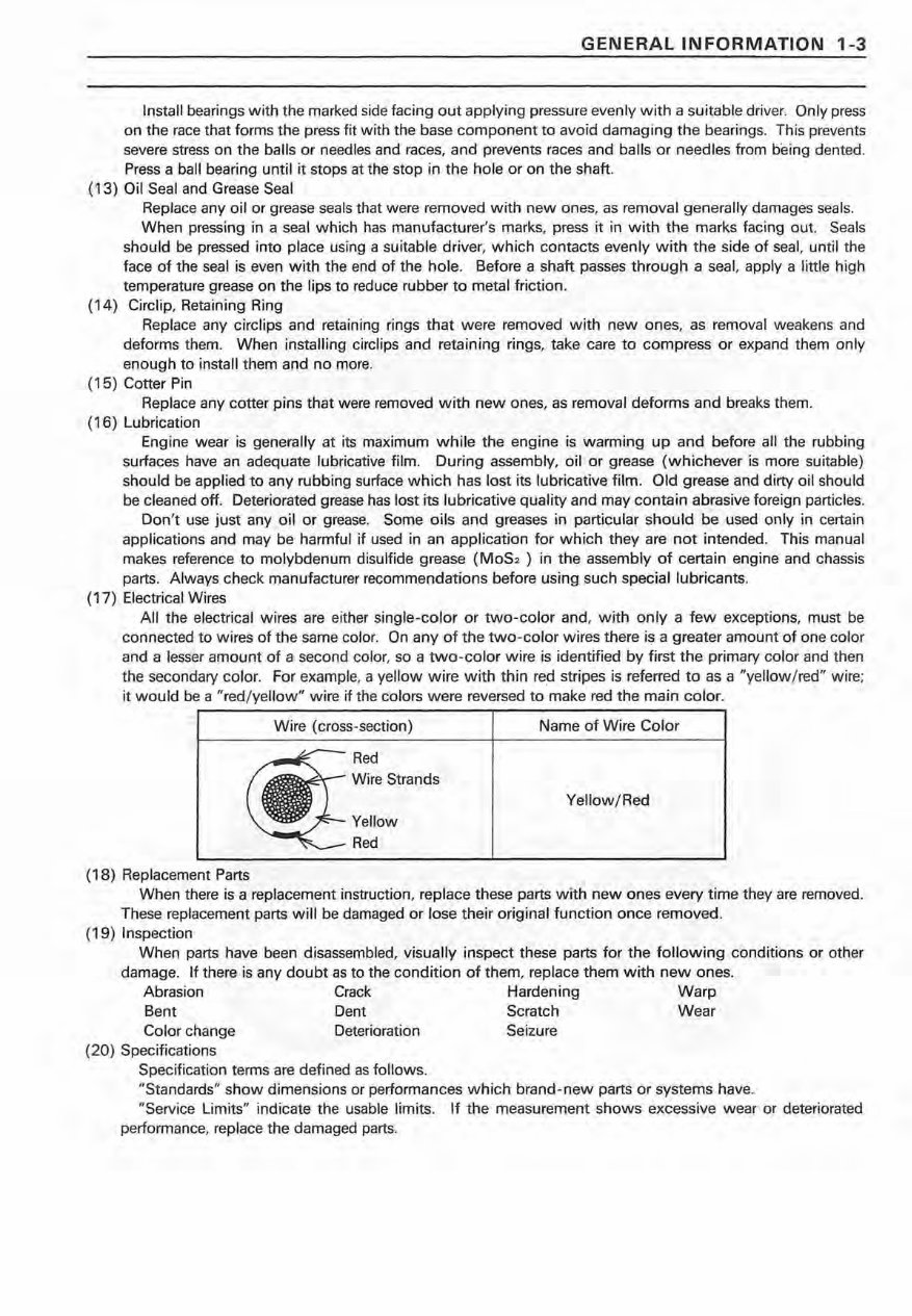
GENERAL INFORMATION 1-3 Install bearings with the marked side facing out applying pressure evenly with a suitable driver. Only press on the race that forms the press fit with the base component to avoid damaging the bearings. This prevents severe stress on the balls or needles and races, and prevents races and balls or needles from being dented. Press a ball bearing until it stops at the stop in the hole or on the shaft. (13) Oil Seal and Grease Seal Replace any oil or grease seals that were removed with new ones, as removal generally damages seals. When pressing in a seal which has manufacturer's marks, press it in with the marks facing out. Seals should be pressed into place using a suitable driver, which contacts evenly with the side of seal, until the face of the seal is even with the end of the hole. Before a shaft passes through a seal, apply a little high temperature grease on the lips to reduce rubber to metal friction. (14) Circiip, Retaining Ring Replace any circiips and retaining rings that were removed with new ones, as removal weakens and deforms them. When installing circlips and retaining rings, take care to compress or expand them only enough to install them and no more. (15) Cotter Pin Replace any cotter pins that were removed with new ones, as removal deforms and breaks them. (16) Lubrication Engine wear is generally at its maximum while the engine is warming up and before all the rubbing surfaces have an adequate lubricative film. During assembly, oil or grease (whichever is more suitable) should be applied to any rubbing surface which has lost its lubricative film. Old grease and dirty oil should be cleaned off. Deteriorated grease has lost its lubricative quality and may contain ab~asive foreign particles. Don't use just any oil or grease. Some oils and greases in particular should be used only in certain applications and may be harmful if used in an application for which they are not intended. This manual makes reference to molybdenum disulfide grease (MOS2 ) in the assembly of certain engine and chassis parts. Always check manufacturer recommendations before using such special lubricants. (17) Electrical Wires All the electrical wires are either si ngle-color or two-color and, with only a few exceptions, must be connected to wires of the same color. On any of the two-color wires there is a greater amount of one color and a lesser amount of a second color, so a two-color wire is identified by first the primary color and then the secondary color. For example, a yellow wire with thin red stripes is referred to as a "yellow/red" wire; it would be a "red/ yellow" wire if the colors were reversed to make red the main color. (18) Replacement Parts Wire (cross-section) Red Wire Strands Yellow Red Name of Wire Color Yellow/Red When there is a replacement instruction, replace these parts with new ones every time they are removed . These replacement parts will be damaged or lose their original function once removed. (19) Inspection When parts have been disassembled, visually inspect these parts for the following conditions or other damage. If there is any doubt as to the condition of them, replace them with new ones. Abrasion Crack Hardening Warp Bent Dent Scratch Wear Color change Deterioration Seizure (20) Specifications Specification terms are defined as follows. "Standards" show dimensions or performances which brand-new parts or systems have. "Service Limits" indicate the usable limits. If the measurement shows excessive wear or deteriorated performance, replace the damaged parts.
Get the factory repair manual for the 1997-2002 Kawasaki Prairie 400 ATV, covering all 2wd and 4x4 models. This service manual is essential for both professional mechanics and DIY enthusiasts. It contains comprehensive information for repairing, maintaining, rebuilding, refurbishing, or restoring your motorcycle. The manual includes complete tear down and rebuild procedures, part diagrams, torque specifications, maintenance guidelines, troubleshooting information, and more.
The manual covers the following:
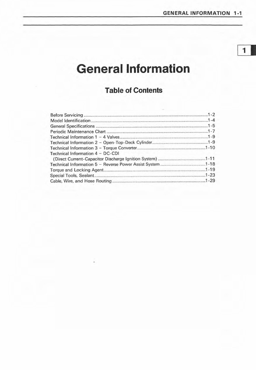
General Information
Periodic Maintenance
Fuel System
Engine Top End
Engine Right Side
Recoil Starter
Engine Lubrication System
Engine Removal/Installation
Crankshaft/Transmission
Wheels/Tires
Final Drive
Brakes
Suspension
Steering
Frame
Electrical System
Appendix
Product Details:
File Format: PDF
Total Pages: 527 pages
Printable: Yes, without any restriction
Delivery: A download link will appear on the checkout page after payment is complete
Requirements: Adobe Reader
Ensure you have the right repair manual for your motorcycle to save on repair and maintenance costs. With this manual, you can preview some pages before making a purchase. Customer satisfaction is guaranteed. Opt for instant download to save on repair and maintenance costs without the need for shipping. Get this manual now and complete all your repairs today for full value for money!

")