

1987-2004 Kawasaki KSF250 Mojave 250 ATV Service & Repair Manual
What's Included?
Fast Download Speeds
Online & Offline Access
Access PDF Contents & Bookmarks
Full Search Facility
Print one or all pages of your manual

KSF250
Kawasaki MOJAVE
All Terrain Vehicle
Service Manual
This quick reference guide will
assist you in locating a desired
topic or procedure.
• Bend the pages back to match
the black tab of the desired
chapter number with the black tab
on the edge at each table of
contents page.
• Refer to the sectional table of
contents for the exact pages to
locate the specific topic required.
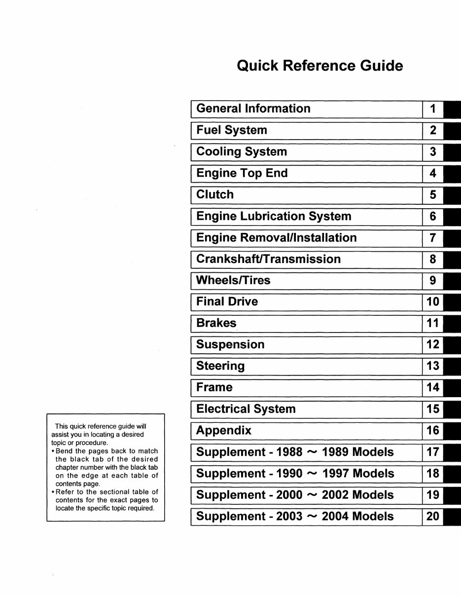
Quick Reference Guide
General Information
Fuel System
Cooling System
Engine Top End
Clutch
Engine Lubrication System
Engine Removal/Installation
CrankshaftlTransmission
WheelslTires
Final Drive
Brakes
Suspension
Steering
Frame
Electrical System
Appendix
Supplement - 1988 ,..., 1989 Models
Supplement - 1990 ,..., 1997 Models
Supplement - 2000 ,..., 2002 Models
Supplement - 2003 ,..., 2004 Models

Kawasaki KSF250
MOJAVE
Motorcycle
Service Manual
Fourteenth Edition (1) : Apr. 10, 2003 (K)
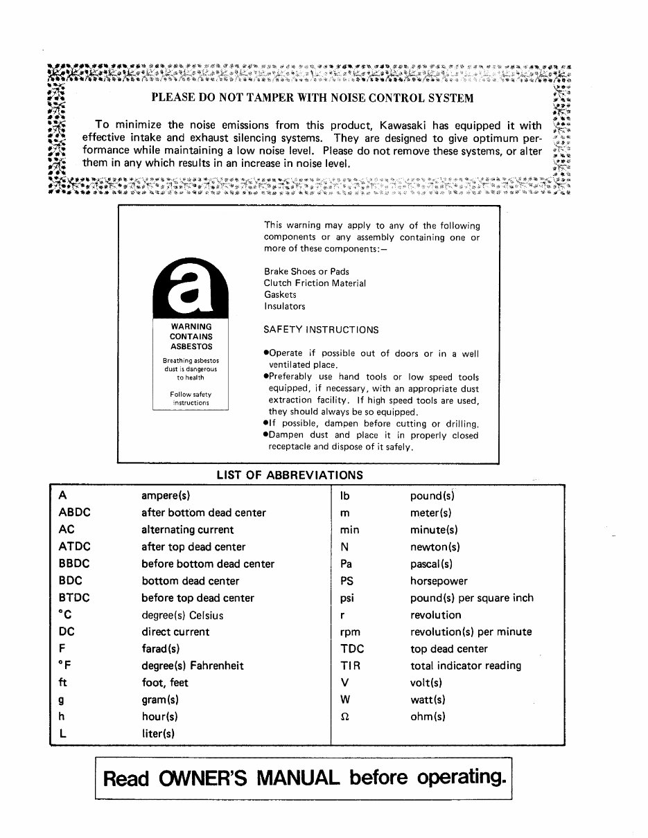
PLEASE DO NOT TAMPER WITH NOISE CONTROL SYSTEM
To minimize the noise emissions from this product, Kawasaki has equipped it with
effective intake and exhaust silencing systems. They are designed to give optimum per-
formance while maintaining a low noise level. Please do not remove these systems, or alter
them in any which results in an increase in noise level.
A
ABOC
AC
ATDC
BBDC
BOC
BTDC
°C
DC
F
of
ft
g
h
L
WARNING
CONTAINS
ASBESTOS
Breathing asbestos
dust is dangerous
to health
Follow safety
instructions
This warning may apply to any of the following
components or any assembly containing one or
more of these components:-
Brake Shoes or Pads
Clutch Friction Material
Gaskets
Insulators
SAFETY INSTRUCTIONS
eOperate if possible out of doors or in a well
ventilated place.
ePreferably use hand tools or low speed tools
equipped, if necessary, with an appropriate dust
extraction facility. If high speed tools are used,
they should always be so equipped.
elf possible, dampen before cutting or drilling.
eDam pen dust and place it in properly closed
receptacle and dispose of it safely.
LIST OF ABBREVIATIONS
ampere(s) Ib pound(s)
after bottom dead center m meter(s)
alternating current min minute(s)
after top dead center N newton (5)
before bottom dead center Pa pascal (s)
bottom dead center PS horsepower
before top dead center psi pound (s) per square inch
degree(s) Celsius r revolution
direct current rpm revolution (5) per minute
farad(s) TOe top dead center
degree(s) Fahrenheit TIR total indicator reading
foot, feet V volt(s)
gram(s) W watt(s)
hour(s) n ohm{s)
liter(s)
I Read OJVNER'S MANUAL before operating. I
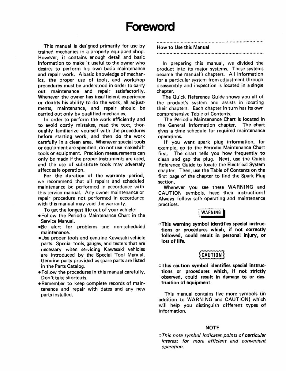
Foreword
This manual is designed primarily for use by
trained mechanics in a properly equipped shop.
However, it contains enough detail and basic
information to make it useful to the owner who
desires to perform his own basic maintenance
and repair work. A basic knowledge of mechan-
ics, the proper use of tools, and workshop
procedures must be understood in order to carry
out maintenance and repair satisfactorily.
Whenever the owner has insufficient experience
or doubts his ability to do the work, all adjust-
ments, maintenance, and repair should be
carried out only by qualified mechanics.
In order to perform the work efficiently and
to avoid costly mistakes, read the text, thor-
oughly familiarize yourself with the procedures
before starting work, and then do the work
carefully in a clean area. Whenever special tools
or equipment are specified, do not use makeshift
tools or equipment. Precision measurements can
only be made if the proper instruments are used,
and the use of substitute tool'S may adversely
affect safe operation.
For the duration of the warranty period,
we recommend that all repairs and scheduled
maintenance be performed in accordance with
this service manual. Any owner maintenance or
repair procedure not performed in accordance
with this manual may void the warranty.
To get the longest life out of your vehicle:
- Follow the Periodic Maintenance Chart in the
Service Manual.
-Be alert for problems and non-scheduled
maintenance.
-Use proper tools and genuine Kawasaki vehicle
parts. Special tools, gauges, and testers that are
necessary when servicing Kawasaki vehicles
are introduced by the Special Tool Manual.
Genuine parts provided as spare parts are listed
in the Parts Catalog.
-Follow the procedures in this manual carefully.
Don't take shortcuts.
- Remember to keep complete records of main-
tenance and repair with dates and any new
parts installed.
How to Use this Manual
In preparing this manual, we divided the
product into its major systems. These systems
became the manual's chapters. All information
for a particular system from adjustment through
disassembly and inspection is located in a single
chapter.
The Quick Reference Guide shows you all of
the product's system and assists in locating
their chapters. Each chapter in turn has its own
comprehensive Table of Contents.
The Periodic Maintenance Chart is located in
the General Information chapter. The chart
gives a time schedule for required maintenance
operations.
If you want spark plug information, for
example, go to the Periodic Maintenance Chart
first. The chart tells you how frequently to
clean and gap the plug. Next, use the Quick
Reference Guide to locate the Electrical System
chapter. Then, use the Table of Contents on the
first page of the chapter to find the Spark Plug
section.
Whenever you see these WARNING and
CAUTION symbols, heed their instructionsl
Always follow safe operating and maintenance
practices.
I WARNING I
o This warning symbol identifies special instruc-
tions or procedures which, if not correctly
followed, could result in personal injury, or
loss of life.
o This caution symbol identifies special instruc-
tions or procedures which, if not strictly
observed, could result in damage to or des-
truction of equipment.
This manual contains five more symbols (in
addition to WARNING and CAUTION) which
will help you distinguish different types of
information.
NOTE
o This note symbol indicates points of particular
interest for more efficient and convenient
operation.
elndicates a procedural step or work to be done.
olndicates a procedural sub-step or how to do
the work of the procedural step it follows.
It also precedes the text of a WARNING,
CAUTION, or NOTE.
*Indicates a conditional step or what action to
take based on the results of the test or inspec-
tion in the procedural step or sub-step it
follows.
*Indicates a conditional sub-step or what action
to take based upon the results of the condi-
tional step it follows.
In most chapters an exploded view illustration
of the system components follows the Table of
Contents. In these illustrations you will find
the instructions indicating which parts require
specified tightening torque, oil, grease or a
locking agent during assembly.
GENERAL LUBRICATION 1-1
General Information
Table of Contents
Before Servicing .......................................... .
Model Identification ....................................... .
General Specifications ..................................... .
Periodic Maintenance Chart ................................. .
Torque and Locking Agent .................................. .
Cable and Harness Routing .................................. .
1-2
1-4
1-5
1-7
1-8
1-10
1~2 GENERAL INFORMATION
Before Servicing
Before starting to perform an inspection service or carry out a disassembly and reassembly operation on a motorcycle,
read the precautions given below. To facilitate actual operations, notes, illustrations, photographs, cautions, and detailed
descriptions have been included in each chapter wherever necessary. This section explains the items that require particular
attention during the removal and reinstallation or disassembly and reassembly of general parts.
Especially note the following:
(1) Dirt
Before removal and disassembly, clean the motorcycle. Any dirt entering the engine will shorten the life of the
motorcycle. For the same reason, before installing a new part, clean off any dust or metal filings.
(2) Battery Ground
Disconnect the ground (-) wire from the battery before performing any disassembly operations on the motorcycle.
This prevents the engine from accidentally turning over while work is being carried out, sparks from being generated
while disconnecting the wires from electrical parts, as well as damage to the electrical parts themselves. For
reinstallation, first connect the positive wire to the positive (+) terminal of the battery
(3) Installation, Assembly
Generally, installation or assembly is the reverse of removal or disassembly. However, if installation or assembly
sequence is given in this Service Manual, follow it. Note parts locations and cable, wire, and hose routing during
removal or disassembly so they can be installed or assembled in the same way. It is preferable to mark and record
the locations and routing whenever possible.
(4) Tightening Sequence
When installing bolts, nuts, or screws for which a tightening sequence is given in this Service Manual, make sure
to follow the sequence. When installing a part with several bolts, nuts, or screws, start them all in their holes and
tighten them to a snug fit, thus ensuring that the part has been installed in its proper location. Then, tighten them
to the specified torque in the tightening sequence and method indicated. If tightening sequence instructions are not
given, tighten them evenly in a cross pattern. Conversely, to remove a part, first loosen all the bolts, nuts, or screws
that are retaining the part a 1/4-turn before removing them.
(5) Torque
When torque values are given in this Service Manual, use them. Either too little or too much torque may lead to
serious damage. Use a good quality, reliable torque wrench.
(6) Force
Common sense should dictate how much force is necessary in assembly and disassembly. If a part seems especially
difficult to remove or install, stop and examine what may be causing the problem. Whenever tapping is necessary, tap
lightly using a wooden or plastic-faced mallet. Use an impact driver for screws (particularly for the removing screws
held by non-permanent locking agent) in order to avoid damaging the screw heads.
(7) Edges
Watch for sharp edges, as they could cause injury through careless handling, especially during major engine
disassembly and assembly. Use a clean piece of thick cloth when lifting the engine or turning it over.
(8) High-Flash Point Solvent
A high-flash point solvent is recommended to reduce fire danger. A commercial solvent commonly available in North
America is standard solvent (generic name). Always follow manufacturer and container directions regarding the use
of any solvent.
(9) Gasket, a-Ring
Replace a gasket or an a-ring with a new part when disassembling. Remove any foreign matter from the mating
surface of the gasket or a-ring to ensure a perfectly smooth surface to prevent oil or compression leaks.
(10) Liquid Gasket, Locking Agent
Clean and prepare surfaces where liquid gasket or non-permanent locking agent will be used. Apply them sparingly.
Excessive amount may block engine oil passages and cause serious damage.
(11) Press
When using a press or driver to install a part such as a wheel bearing, apply a small amount of oil to the area
where the two parts come in contact to ensure a smooth fit.
(12) Ball Bearing and Needle Bearing
Do not remove a ball bearing or a needle bearing unless it is absolutely necessary. Replace any ball or needle
bearings that were removed with new ones. Install bearings with the manufacturer and size marks facing out, applying
pressure evenly with a suitable driver. Apply force only to the end of the race that contacts the press fit portion, and
press it evenly over the base component.
(13) Oil Seal and Grease Seal
Replace any oil or grease seals that were removed with new ones, as removal generally damages seals. Oil or
grease seals should be pressed into place using a suitable driver, applying a force uniformly to the end of seal until
the face of the seal is even with the end of the hole, unless instructed otherwise. When pressing in an oil or grease
seal which has manufacturer's marks, press it in with the marks facing out.
GENERAL INFORMATION 1-3
(14) Circlip, Retaining Ring, and Cotter Pin
When installing circlips and retaining rings, take care to compress or expand them only enough to install them and
no more. Install the circlip with its chamfered side facing load side as well.
Replace any circlips, retaining rings, and cotter pins that were removed with new ones, as removal weakens and
deforms them. If old ones are reused, they could become detached while the motorcycle is driven, leading to a major
problem.
(15) Lubrication
Engine wear is generally at its maximum while the engine is warming up and before all the sliding surfaces have
an adequate lubricative film. During assembly, make sure to apply oil to any sliding surface or bearing that has been
cleaned. Old grease or dirty oil could have lost its lubricative quality and may contain foreign particles that act as
abrasives; therefore, make sure to wipe it off and apply fresh grease or oil. Some oils and greases in particular should
be used only in certain applications and may be harmful if used in an application for which they are not intended.
(16) Direction of Engine Rotation
To rotate the crankshaft manually, make sure to do so in the direction of positive rotation. Positive rotation is
counterclockwise as viewed from the left side of the engine. To carry out proper adjustment, it is furthermore necessary
to rotate the engine in the direction of positive rotation as well.
(17) Replacement Parts
When there is a replacement instruction, replace these parts with new ones every time they are removed.
Replacement parts will be damaged or lose their original function once they are removed. Therefore, always
replace these parts with new ones every time they are removed. Although the previously mentioned gasket, O-ring,
ball bearing, needle bearing, grease seal, oil seal, circlip, and cotter pin have not been so deSignated in their respective
text, they are replacement parts.
(18) Electrical Wires
All the electrical wires are either one-color or two-color. A two-color wire is identified first by the primary color and
then the stripe color. For example, a yellow wire with thin red stripes is referred to as a "yellow/red" wire; it would
be a "red/yellow" wire if the colors were reversed. Unless instructed otherwise, electrical wires must be connected to
wires of the same color.
Two-Color Electrical
Wire (cross-sect ion)
Color Indicated on tne Wire Color Indicated on the Wiring Diagram
Red
Wire Strands
Ye I low/Red ---Y/R---
Ye I low
Red
GB020601Wl C
(19) Inspection
When parts have been disassembled, visually inspect these parts for the following conditions or other damage. If
there is any doubt as to the condition of them, replace them with new ones.
Abrasion Crack Hardening
Bent Dent Scratch
Color change Deterioration Seizure
(20) Specifications
Specification terms are defined as follows:
"Standards" show dimensions or performances which brand-new parts or systems have.
Warp
Wear
"Service Limits" indicate the usable limits. If the measurement shows excessive wear or deteriorated performance,
replace the damaged parts.
1-4 GENERAL INFORMATION
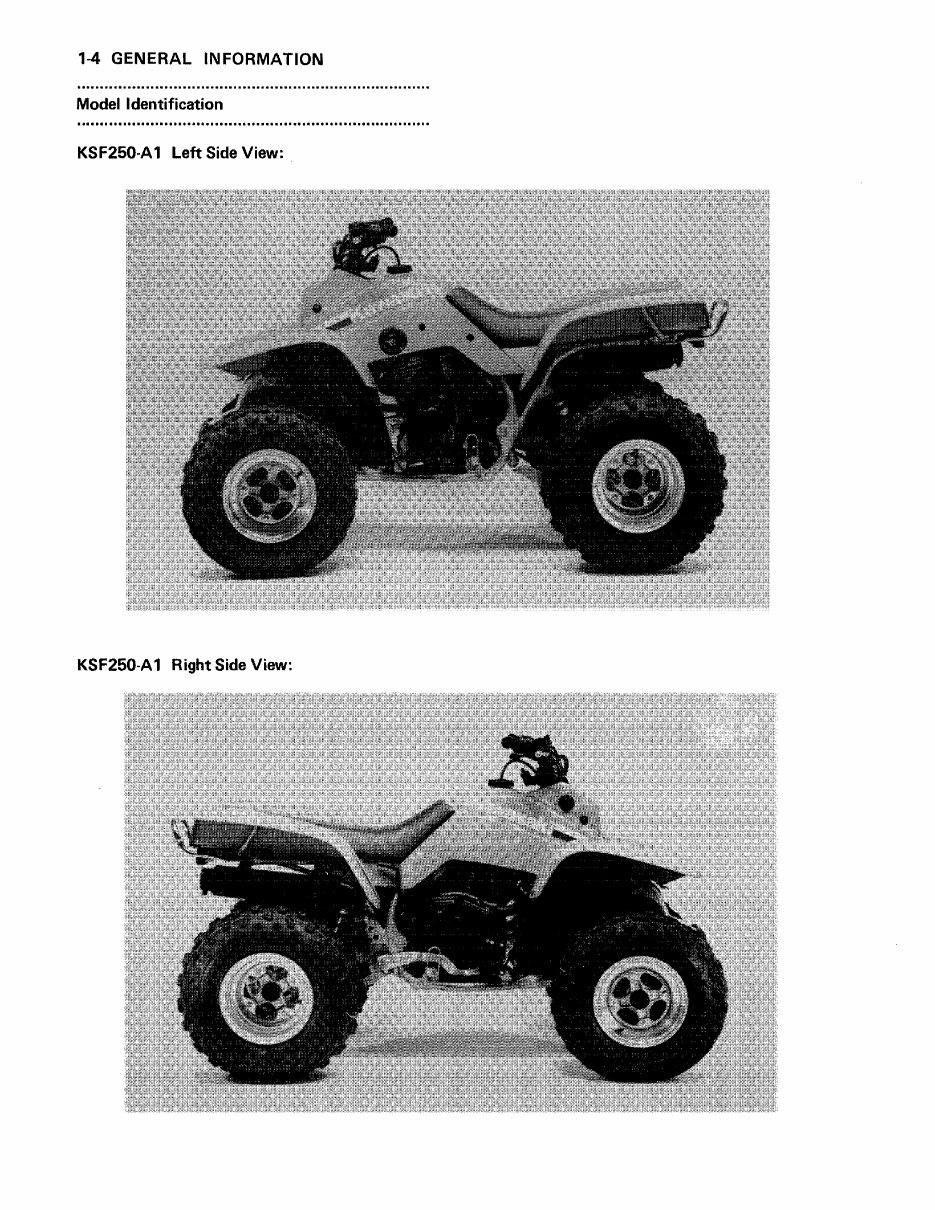
Model Identification
KSF250-A 1 Left Side View:
KSF250-A 1 Right Side View:
You're Reading a Preview
What's Included?
Fast Download Speeds
Online & Offline Access
Access PDF Contents & Bookmarks
Full Search Facility
Print one or all pages of your manual
$31.99
Viewed 19 Times Today


Secure transaction
What's Included?
Fast Download Speeds
Online & Offline Access
Access PDF Contents & Bookmarks
Full Search Facility
Print one or all pages of your manual
$31.99
Get instant access to the Complete Factory Service Repair Workshop Manual without any extra fees or expiry dates. This Professional Manual is suitable for both professional Mechanics and DIY enthusiasts, covering all repairs, servicing, and troubleshooting procedures with step-by-step instructions, detailed photos, diagrams, and highly detailed exploded diagrams & pictures. You can print out a single page or the entire manual as per your choice. The Manual can be used on multiple computers without any limitations or trial periods and is compatible with all Windows & MAC Computers. There's no need to renew or pay any extra, as this Manual can be used for life.


