

Kawasaki KL T 110/160
MODEL COVERAGE
KLT 110-A1
KLT 110-A2
KLT 160-A 1
INDEX
GENERAL SPECiFiCATIONS ................................................ 556 ~~~.. . ... ~
External Shift Mechanism .........................................577
MAINTENANCE ............................... ............... ....... 556 Lower End and Transmission .........................577
Lubrication ............ ......................... 556 Splitting the Crankcases .....................................577
Motor Oil ...................................................................... 556
Crankcase Assembly ..................................................... 577
Checking Oil Level..................... ................ ..... 556 Engine Specifications ........................................... 580-581
Changing Oil ................ .. ................................................. 556
Engine Torque Specifications ............................................. 579
Filter Screen .............................................................. ... .557
Final Gear Case ............................................................... 557
Front Forks ......................................................................557
Drive Chain (KLT 110) ...................................................... 557
General lubrication '" ....................... .. .......................... 558
Service Checks and Adjustments ..................................... 558
Drive Chain (KLT 110) ...................................................... 558
Clutch ..............................................................................558
Throttle Cable ............................................................... 558
FUEL SYSTEMS ........ .. .................................. .. ..................... 582
Gas Tank ............................................................ .............. 582
Carburetor (KLT 110) .. ......... ............... ....... .... ............ .. ... 582
Carburetor (KLT 160) ......................................................... 582
Fuel Petcock ................................................... ..... .......... ..... 583
Air Cleaner ........... ........................................ .. ..... ........ 584
Fuel Line s. .................................................. .. .......... 584
Carburetor Specifications .................................................584
Front Brake .................... ............... ................. ..... 558
Rear Brake .... ................ ............... ................ .. .. 559
Steering Stem . .................. .. ............... 559
Fuel System .....................................................................559
AAR~....................................................... .. .._
ELECTRICAL SYSTEM ....... .... .. . ... ....... ....... .. .:..................... 584
Ignition System.......... .. .................................................584
Lighting System ................................................ .. ............... 588
Wiring Diagrams..... .. ................... 586-587
Petcock .......... ................... .. ... 560
Carburetor ......... ...... ..... .. ......................560
Recommended Lubricants .......................561
Periodic Maintenance Intervals............ .................. .. ..... 561
Maintenance Data ..................................................... ........560
CHASSIS ................. ................. ............. 588
Component Removal and Installation .............. ............. ...... 588
Seat........... .. .............. .. .. .............. ......................... 588
Front Fender .......... .. ...............................................588
Rear Fender... ....... .......................................... 588
TUNE-UP ....................................... .................................. ..... 561
Compression Test ............................................................. 561
Cam Chain Tensioner ........................................ .. .......... 561
Valve Adjustment .......................................................... ..... 562
Ignition Timing ....................................................................562
Carburetor ............................................................... .. ... ..... 562
Adjusting Float Level .................................................. .. .. 562
Id le Speed and Mixture ..................................................562
Spark Arrestor Cleaning ....................................................563
Tune-Up Specifications................................. .. ........ .. 563
Front Wheel ....................................................................... 588
KLT 110-A 1 ..................................................................... 588
KLT 110-A2, KLT 160 .. .............. ....... .......................589
Rear Wheels ..................................................................... 590
Front Wheel Bearings..... ..................... .. ........................ 590
In spection ......................................... .......................... 590
Removal ............................................................. 590
Installation ... .................................................................. 590
Front Brake ........................... . ...................... ... .. 590
Removal and Disassembly .............................................. 590
Inspection ....................................... . .. ..... ......... 590
ENGINE AND TRANSMISSION ............. .. ........ .. . ................ 563
Engine Removal and Installation ........................................ 563
Assembly and Installation .............................................. 590
Front Forks (KLT 110-A 1)........................... ............... 591
Removal....................................... ....................... 591
KLT110 .................................................................. 563
KLT 160 ..... .................................................. .............. .. ..564
Top End............................................................. .... 564
KLT110 ......................................................................... .. 564
KLT 160......... .. .. ............................................ .566
Crankcase Cover Components ........................................... 569
KLT 110 ......... . .... .. .......................................................... 569
Recoil Starter ................................. .. ....... 569
Left Crankcase Cover ................................................. 570
Engine Sprocket .........................................................570
Magneto .....................................................................570
Inspection ..................................................................... 591
Installation. ............................................................. 591
Hydraulic Front Forks ..........................................................591
Removal ............... ............................................ 591
Disassembly .................................................................... 591
Inspection ...... .. ..................................... :..........................592
Assembly ........ ......... ............. ........................................... 592
Changing Fork Oil ............................................................ 592
Insta ll ation .....................................................................592
Steering Stem .. ................................................................... 592
KLT 110-A1 ..................................................................... 592
Clu1ch .........................................................................570
Clutch Release ................ .........................572
KLT 110-A2, KLT 160 ....... .. ................. ....................... ..... 592
Rear Axle .............................................................................593
Primary Drive ................... ........................... 572
KLT 110 ........................................................................... 593
Oil Pump............................. ........................... 572
KLT 160 ........................................................................... 593
External Shift Mechanism. ........................ 572
Rear Brake .... ....... ...................................................... 594
KLT 160 ..................... ......... .. . .. .. ........................ ............ 573
Recoil Starter ....................................................... ..... 573
Left Crankcase Cover.. .. ................ .. ...... ..... 573
Magneto.............. ................. .. .. 574
Reverse Lever ........................................................... 574
Clutches .....................................................................574
Clutch Release .. .......................................................... 575
Primary Drive ..............................................................576
Removal and Disassembly .............................................. 594
Inspection ........................................................................594
Assembly and Installation ................................. 595
Rear Axle Bearings ..............................................................595
KLT 110 ................................595
KLT 160 .........................................................................595
General Torque Specif icat ions ............................ .. ..............595
Chassis Torque Specifications ..................... ... .................... 595
555
..
Kawasaki KL T 110/160
ENGINE
Type
Bore x Stroke (mm/in.)
Displacement (cc/ci)
Compression ratio
Carburetor
Ignition system
Starting system
Lubrication
TRANSMISSION
Clutch
Primary reduction
Transmission type
Gear ratios
1st
2nd
3rd
4th
5th
Reverse
Final drive
Final reduction
Overall reduction
DIMENSIONS
Overall length (mm/in.)
Overall width (mm/in.)
Overall height (mm/in .)
Wheelbase (mm/in .)
Ground clearance (mm/in.)
Seat height (mm/in.)
Dry weight (kg/lbs.)
Turning radius (min.) (m/ft.)
Fuel tank capacity (1/gal.)
FRAME
Type
Caster
Trail (mm/in.)
Track (mm/in.)
Front tire
Rear tires
Brakes (fir)
MAINTENANCE
NOTE: Common maintenance procedures
are expJained in detail in the "General In-
'formation" section of this manual.
LUBRICATION
Molor Oil
I. Use motor oil service rated "SE" or
"SF."
2. For all· temperature use, the following
grades are recommended: SAE IOW·40,
lOW-50, 20W-40or 20W·50.
Checking Oil Level
1. Oil level should be checked every time
before riding the machine.
2. A sight glass for checking oil level is
GENERAL SPECIFICATIONS
KLT110
4-stroke, SOHC
51 .0 x 50.6/2.01 x 1.99
103 /6.2
8.2:1
Keihin PC18
COl
Rope
Wet sump
Centrifugal
3.619 (76/21)
5-speed, constant mesh
3.307 (43/13)
2.111 (38/18)
1.545 (34/22)
1.285 (27121)
1.111 (30/27)
Chain
4.166(50/12)
16.754(5th gear)
1700/66.9
975/38.4
970/38.2
1075/42.3
130/5.1
705/27.8
109/240
1.8/5 .9
9.5/2.5
Tubular, single cradle
19.5"
10/0.39
700/27.6
22 X 11.00-8
22 x 11.00-8
Drum
3. Be sure the machine is parked on a
level surface to ensu re an accurate reading.
4. Level should be checked after tbe en-
gine has been running for a few minutes. Shut
it orf and let the oil settle for a minute or so.
5. Oil level should be between the upper
and lower l evel marks inscribed on the crank-
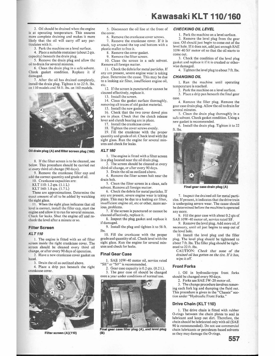
fitted to the right crankcase cover. Oillevel.ighl gla •• CA) and lavel markl (8)
556
KLT160
4-stroke, SOHC
61 .0 x 52.4/2.40 x 2.06
153 /9.3
9.5:1
Mikuni VM22SS
COl
Rope
Wet sump
Centrifugal
3.695 (85/23)
5-speed, constant mesh
3.076 (40/13)
1.842 (35/19)
1.304 (30/23)
1.076 (28/26)
0.928 (26/28)
3.384 (28/13 x 33/21)
Shaft
3.712 (2 1/18 x 35/11)
12.738 (5th gear)
1730/68.1
1000/39.4
1000/39.4
1110/43.7
135/5.3
695/27.4
124/273
1.7/5.6
9.5/2.5
Tubular , semi-double cradle
23"
17/0.70
740/29.1
21 x 9.00-8
22 x 11.00-8
Drum
case. If the level is too l ow. add just enough
lubricant of the correct grade to bring it up
between the marks. Do not ove rfill.
Changing Oil
I. The oi l should be cha nged every 30
days when the machine is in reg ul ar use.
Oil drain plug (A) (110)
2. Oil should be drained when the engine
is at operat ing temperature. This ensures
more compl ete draining and makes it more
likely that the oi l will carry off any par-
ticula tes with it.
3. Park the mac hine on a level s urface.
4. Place a s ui ta ble container (about 2q ts.
capacity) beneath the drain plug.
5. Remove the drain plug and allow the
oil to drain for several minutes.
6. C lean the drain plug in a safe solvent.
Check gasket condition. Replace it if
damaged.
7. After the oil has drained completely,
insta ll the drain plug. Tighten it to 22 fe Ibs.
on 110 models and 58 ft. Ibs. on 160 models.
Oil drain plug (A) and filter Icreen plug (160)
8. If the filter screen is to be cleaned, see
below. This procedure should be carried out
at every third oil change (90 days) .
9. Remove the crankcase filler cap and
add the correct quantity and grade of oil.
10. Crankcase capacit ies are:
KLTIW,1.2qts.(1.1L)
KLT I 60,1.8qts.(1.7L)
These are app roximations. Dete rmine the
exact amount of oil to be added by watching
the sight glass.
II. When the sight glass in dica tes that o il
level is correct, install the filler cap, start the
engine and a llow it to run for several minutes.
Check for leaks. Shut the engine off and re-
check the level after a minute or so.
Filter Screen
KLT110
1. The cnginc is fitted with an oil filter
screen ins id e the right crankca se cover. The
screen should be cleaned every third oil
cha nge, or after every 90 days of operation.
2. Have a new crankcas e cover gasket on
hand.
3. Drain the oil as outlined above.
4. Place a dr ip pan beneath the right
crankcase cover.
FiIt.r screen (A)(110)
Kawasaki KL T 110/160
5. Disconnect the oil line at the front of
the cover.
6. Remove the crankcase cover screws.
7. Remove the crankcase cover. If it is
stuck, tap around the top and bottom with a
plastic ma ll et to free it.
8. Remove the cover gasket.
9. Remove the filter screen.
10. Clean the screen in a safe solvent.
Remove all foreign matter.
11. Check the debris for met al particles. If
any are present, severe engine wear is taking
place. Determine the cause. Th is may be due
to a leak in g air filter, insufficient engine oil,
etc.
12. If the screen is punctured or cannot be
cleaned effectively, replace it.
13. Install the screen.
14. Clean the gasket surface thoroughly,
removing all traces of old gasket material.
15. Install the new gasket.
16. Check that the two cover dowel pins
are in place. Check that the clutch release
lever and clutch bearing are in place.
17. Install the crankcase cover.
18 . Tighten the cover screws evenly.
19. Rll the crankcase wi th the proper
quantity and grade of oil. Check level with the
sight gl ass. Run the engine for several min-
utes and check for leaks.
KLT160
1. The engine is fitled with a filter screen
in a plug located near the oi l dra in pl ug.
2. The screen shou ld be cleaned at every
third oil change, or after every 90 days.
3. Drain the oil as outlined above.
4. Remove the filter sc reen bolt near the
drain bolt.
5. Clean the 'filt er screen in a clean, safe
solvent. Remove all foreign matter.
6. Check the debris fo r metal particles. If
any are present, severe engine wear is taking
place. This may be due to a leaking air filter,
insufficient eng in e oi l, etc or other, more ser-
ious, problems.
7. If the screen is punctured or cannot be
cleaned effectively. replace it.
8. In spect the plug gasket and replace it
if damaged.
9. Insta ll the plu g and tighten it to 58 f1.
Ibs.
10. Fill the crankcase with the proper
grade a nd quantity of oil. Check level with the
sight glass. Run the engine for several min-
utes and check for leaks.
Final Gear Case
I. SAE IOW-40 motor oil, service rated
"SE" or "SF" is recommended.
2. Gear case capacity is 0.2 qts. (0 .2 L).
3. The gear case oil shou ld be changed
once a year under conditions of normal use.
(8)
CHECKING OIL LEVEL
1. Park the machine on a level surface.
2. Remove the level plug from the gear
case. Oil should just begin to come out of the
level holc. Ifit does not, add just enough SAE
10W·40 SF motor oil so that the oil sta rts to
come out.
3. Check the condition of the level plug
gasket and replace it if it is crushed or other-
wise damaged.
4. Tighten the level plug to about 7 ft.lbs.
CHANGING OIL
1. Run the machine until operat ing
temperature is reached.
2. Park the machine on a level surface.
3. Place a drip pan beneath the final gear
case.
4. Remove the filler plug. Remove the
gear casedrain plug. Allow the oi l to drain for
several minutes.
5. Clean the drain plug thoroughly in a
safe solven t. Check gasket condition. Us ing a
new gasket is recommended.
6. Install the drain plug. Tighten it to 22
ft.lbs.
Final gear cas. drain plug (A)
7. Inspect the drained oil for metal parti -
cles. If present, it indicates that the dr ive tra in
is undergoing severe wear. The ca use should
be determi ned before the machine is operated
any more.
8. Fill the gear case with about 0.2 qts of
SAE I OW· 40 motor oi l. service rated SF.
9. Remove the level plug. Add more oi l, if
necessar y, until oi l just begins to seep out of
the level hole.
10. Install the level plug and the filler
plu g. Th e level p lu g shou ld be tightened to
about 7 ft. Ibs. The filler plug should be tight-
ened to 22 f1. lbs.
CAUTI ON: Check that none of the
drained oil has gotten on the lire. lfit has,
wipe it o fr.
Front Forks
I. Oil in hydraulic-type front forks
should be changed every 90 days.
2. Forks useSAE5W-20 motor oil.
3. The change procedure in volves remov-
ing each fo rk leg and dumping the fluid o Ul.
This procedure is given in the "Chassis" sec-
tion under " H ydro.ulic Front Forks."
Drive Chain (KL T 110)
1. The drive cha in is fitted with rubber
O-rings between the cha in plates to seal in
lubricant and keep out dirt. Therefore, the
chain should be lubricated only with oil (SAE
90 is recommended). Do not use commercial
chain lubricants or petroleum-based solvents
as they may damage the O-rings.
557
•
Kawasaki KL T 110/160
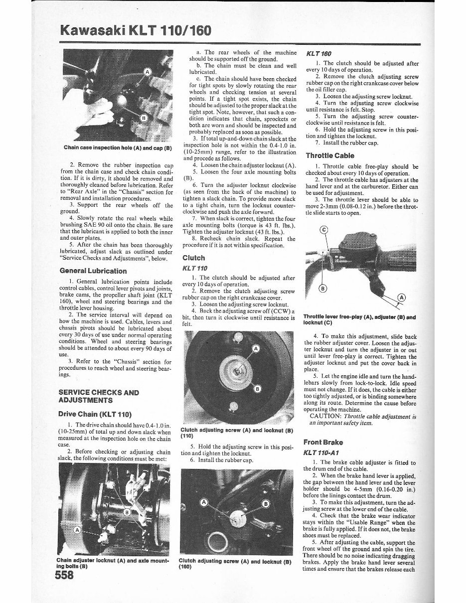
Chain case inspection hole (A) and cap (9)
2. Remove the rubber im:pection cap
from the chain case and check chain condi·
tion. If it is dirty. it shou ld be removed and
thoroughly cleaned before lubrication. Refer
to "Rear Axle" in the "Chassis" section for
removal and installation procedures.
3. Support the rear wheels off the
ground.
4. Slowly rotate the real wheels while
brushing SAE 90 oil onto the chain. Be sure
that the lubricant is applied to both the inner
and outer plates.
5. After the chain has been thoroughly
lubricated. adjust slack as outlined under
"Service Checks and Adjustments", below.
General lubrication
I. General lubrication points include
control cables, control lever pivots and joints,
brake cams, the propeller shaft joint (KLT
160), wheel and steeriug bt:arings and the
throttle lever housing.
2. The service interval will depend on
how the machine is used. Cables, levers and
chassis pivots should be lubricated about
every 30 days of use under normal operating
conditions. Wheel and steering bearings
should be attended to about every 90 days of
use.
3. Refer to the "Chass i s" section for
procedures to reach wheel and steering bea r-
ings.
SERVICE CHECKS AND
ADJUSTMENTS
Drive Chain (Kl T 110)
I. The drive chain should have 0.4-1.0 in.
(10-25mm) of total up and down slack when
measured at the inspection hole on the chain
case.
2. Before check ing or adjusting cha in
slack. the fo llowing conditions must be met:
Chain adjuster locknut (A) and axle mount·
ing bolts (B)
558
a. The rear wheels of the machine
should be supported off the ground.
b. The chain must be clean and well
lubricated.
c. The chain shou ld have been checked
for tight spots by slowly rotating the rear
wheels and checking tension at severa l
points. If a tight spot exists, the chain
should be adjusted to the proper slack at the
tight spot. Note, however, that such a con-
dition indicates that chain, sprockets or
both are worn and should be inspected and
probably replaced as soon as possible.
3. If total up-and-down cha in slack at the
inspection hole is not within the 0.4-1.0 in.
(lO-25mm) range, refer to the illustration
and procede as follows.
4. Loosen the chain adjuster locknut (A).
5. Loosen the four axle mounting bolts
(B) .
6. Turn the adjuster locknut clockwise
(as seen from the back of the machine) to
tighten a slack chain. To provide more slack
to a tight chain. turn the locknut counter-
clockwise and push !he axle forward.
7. When slack is correct, tighten the four
axle mounting bolts (torque is 43 f1. Ibs.).
Tighten the adjuster locknut (43 ft. Ibs.).
8. Recheck chain slack. Repeat the
procedure if it is not within specification.
Clutch
KLT110
1. The clutch should be adjusted after
every 10 days of operation.
2. Remove the clutch adjusting screw
rubber cap on the right crankcase cover.
3. Loosen the adjusting screw locknut.
4. Back the adjusting screw off (CCW) a
bit, then turn it clockwise until resistance is
felt.
Clutch adjusting screw (A) and locknut (8)
(110)
5. Hold the adjusting screw in this posi-
tion and tighten the locknut.
6. Install the rubber cap.
Clutch adjusting screw (A) and locknut (8)
(160)
KLT160
I. The clutch should be adjusted after
every 10 days of operation.
2. Remove the clutch adjusting screw
rubber capon the right crankcase cover below
the oil filler cap.
3. Loosen the adjusting screw locknut.
4. Turn the adjusting screw clockwise
until resistance is felt. Stop.
5. Turn the adjusting screw counter-
clockwise until resistance is felt.
6. Hold the adjusting sc rew in this posi-
tion and tighten the locknut.
7. Install the rubber cap.
Throttle Cable
1. Throttle cab le free-play should be
checked about every 10 days of operation.
2. The throttle cable has adjusters at the
hand lever and at the carburetor. Either can
be used for adjustment.
3. The throttle lever should be able to
move 2-3mm (0.OS -0.12 in.) beforc the throt-
tle slide sta rts to open.
Throttle lever fr ... pla1 (A), adjuster (B) and
locknut (C)
4. To make this adjustment, slide back
the rubber adjuster cover. Loosen the adjus-
ter locknut and turn the adjuster in or out
un til lever frce·play is correct. Tighten the
adjuster locknut and put the cover back in
place.
5. Let the engine idle and turn the hand-
lebars slowly from lock-to-Iock. Idle speed
must not change. If it does, the cable is either
too tightly adjusted, or is binding somewhere
along its route. Determine the cause before
operating the machine.
CAUTION: Throttle cable adjustment is
an important safety item.
Front Brake
KLT11D-A1
1. The brake cab le adjuster is fitted to
the drum end of the cable.
2. When the brake hand lever is applied,
the gap between the hand lever and the lever
holder should be 4-5mm (0.16-0.20 in.)
before the linings contact the drum.
3. To make this adjustment , turn the ad-
justing screw at the lower end of the cable.
4. Check that the brake wear indicator
stays within the "Usable Range" when the
brake is fully applied. If it does not, the brake
shoes must be replaced.
5. After adjusting the cable, support the
front wheel off the ground and spin the tire.
There should be no noise indicating dragging
brakes. Apply the brake hand lever several
times and ensure that the brakes release each
time. If they do not, determine t he cause-and~
remedy the co ndition. Possible causes incl ude
a binding cable due to dirt, corrosion or incor -
rect routing, worn or d amaged brake return
sprin gs or a corroded or damaged brake cam.
6. When the brake hand lever is fully
app lied, the ang le formed by the lever at the
dr um an d the cable should be 80·90· for max-
imum bra ke effectiveness. If not within this
specificat ion, it is possible to remove the lever
from the spli ned shaft and reposition it so that
the angle is cor rect.
CAUTION: Do not change the position of
the brake wear indicator.
KL T 110- A2, KL T 160
I. Brake cable adjusters arc fitted to the
hand lever bracket and to the brake drum.
Use the upper adjuster for minor brak e ad-
justments. When it starts to pass about half of
its adjustment range, use the adjuster at the
drum.
2. When the brake hand lever is applied,
the gap between the hand lever a nd the lever
holder should be 4- 5mm (0 .16-0.20 in.)
before the linings contac t the drum.
3. Make minor adjustments with the ad-
jus ter at the hand lever. Loosen the adjuster
locknut and screw the adjuster in or out until
the gap is correct, then tighten the locknut.
4. For major a djustments. or when the
handlebar adjuster has used up more than
ha lf of its usa ble range, use the a djuster at the
dru m.
S. Loosen the upper adjuster locknut and
turn the adjuster in all the way. Tighten the
locknu t.
6. Back off the drum adjuster mounting
nuts and slide the adjuster on its bracket so
that hand lever free movement is 4-Smm
(0. 16-0.20 in.).
7. Tighten the mou riti ng nuts. Recheck
adjustment and make minor corrects, if
required, with the hand lever adjuster.
8. After adjusting the cable, support the
front wheel off the ground and spin the tire.
There should be no noise indicating dragging
brakes. Apply the lever several times and
ensu re t he brakes release each time. If they do
not, determine theca use and remedy thecon -
dition. Possible causes include a cab le binding
due to dirt, corrosion or incorrect routing,
worn or damaged brake return springs or
co rroded or damaged brake cam.
Rear Brake
1. Th e rear brake is contro ll ed by both a
hand lever and a foot pedal. Both lever and
pedal must be adjusted at the same time.
2. The brake pedal on KLT 160 models is
adjustable for position. To position the pedal,
back off the rod adjuster, loosen the stop bolt
Brake pedal.diulter (A)
Kawasaki KL T 110/160
locknut and turn the stop bolt so that the
- pedal at- rest position is comf ortable for the
operator. Adjust the pedal travel as outlined
in the following steps.
3. Adjust the brake pedal first. The pedal
shou ld have about 25mm (l in.) of free
movement before the linings contact the
drum . Adjust by means of the adjuster on the
end of the rod or cable al the rear brake drum.
4. To adjust the hand lever, adjusters are
fitted to the han d lever bracket and to the end
of thecable at the brake drum.
5. Use the hand lever adjuster for minor
adju stments. When it sta rts to pass about half
of i ts adjustment range, use the .adju ster at
the brake drum end of the ca bl e.
6. The hand lever should have 4-Smm
(0.16-0.20 in.) of free movement before the
linings con tact the dr um. This distance is
measured between the hand lever and the
lever holder.
Brake hand lever adjuster (A)
7. To adjust at the handlebar, loosen the
adjuster locknut and turn the adjuster in or
out until free play is correct. Tighten the
lockn ut.
8. To adjust at the drum, first screw the
handlebar adjuster all the way in.
9. Turn the adjuste r at the brake d rum
until hand lever free pl ay is correct. Make
minor correction s, if required, with the adjus-
ter at the handl ebar .
10. Afler adjusting both the brake pedal
and the brake hand lever, support the rear
wheels off the ground and check operation.
Spin the wheels and apply both pedal and
lever several times. Ens ure that the brakes
release "full y afte r every application. There
should be no noise to ind icate dragging. If
there i s, determine the (''ause and remedy the
condition. Possible causes include weak or
damaged brake ret urn springs, a corroded or
damaged brake cam, an unlubr ic ated or cor-
roded brake cable, pedal or lever pivot or
incorrectly routed cab le.
Steering Stem
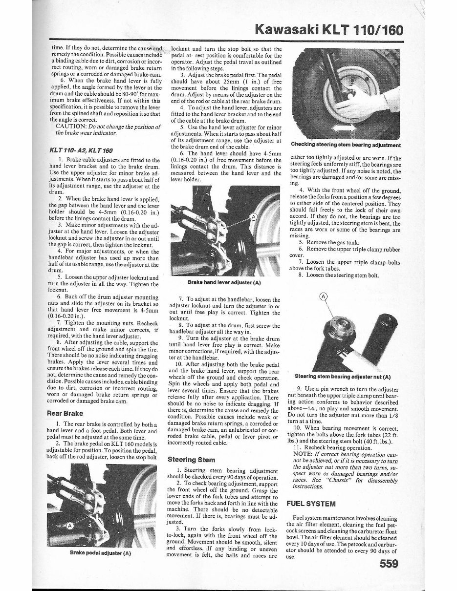
I. Steering stem bearing adjustme nt
should be checked every 90 days of operation.
2. To check bearing adjustment, su pport
the front wheel off the ground. Gra sp the
lower ends of the fork tubes and attempt to
move the forks back a nd forth in line with the
machine. There should be no detectable
movement. If there is, bear ings must be ad-
justed .
3. Turn the forks slowly from lock-
to-lock, aga in with the front wheel off the
ground. Movement should be smooth, silent
and effortless. , If any binding or uneven
movement is felt, the balls and races are
Checking steering stem bearing adjustment
either too tight ly adjusted or are worn. If the
steering feels uniformly stiff, the bearings are
too tightly adjusted. If any noise is noted, the
bearings are damaged and/or some are miss-
ing .
4. With the front wheel off the ground,
release the forks from a position a few degrees
to either sid e of the centered position. They
should fall freely to the lock of their own
accord. If they do not, the bearings are too
tightly adjusted, the steering stem is bent, the
races are worn or some of the bearings are
mi ssing.
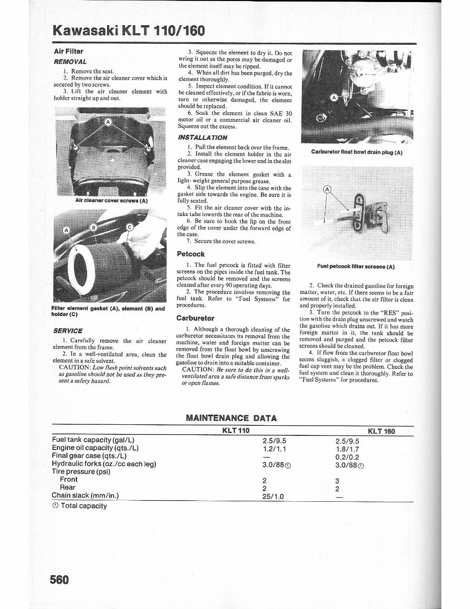
5. Remove the gas tank.
6. Remove the upper triple clamp rubber
cover.
7. Loosen the upper triple clamp oolts
above the fork tubes.
8. Loosen the steering stem bolt.
Steering stem bearing adjulter nut (A)
9. Use a pin wrench to turn the adjuster
nut benea th the upper triple clamp until bear-
ing action conforms to behavior described
above- i.e., no play and smooth movement.
Do not turn the adjuster nut more than 1/8
turn at a time.
10. When bearing movement is correct,
tighten the boilS above the fork tubes (22 f1.
Ibs.) and the steering stem bolt (40 fLlbs .).
II. Recheck bearing operation.
NOTE: If correct bearing operation can-
not be achieved, or ifit is necessary to turn
the adjuster nut more than two turns, su-
spect worn or damaged bearings and/ or
races. See "Chassis" for disassembly
instructions.
FUEL SYSTEM
Fuel system maintenance involvescleaning
the ai r filter element, cleaning the fuel pet-
cock screens and cleaning the car buretor fl oat
bowl. Theair filter element should beclea ned
every 10 da ys of use. The petcock and carbur -
etor should be atte nded to every 90 da ys of
use.
559
Kawasaki KLT 110/160
Air Filter
REMOVAL
1. Remove the seat.
2. Remove the air cleane r cover which is
secured by two screws.
3. Lift the air cleaner element with
holder straight up and out.
Air cleaner cover screws (A)
Filter ,lIIement gasket (A), element (8) and
holder (e)
SERVICE
1. Ca refully remove the air cleaner
element from the frame.
2. In a well-ventilated area, cl ean the
elemen t in a safe solvent.
CAUTION: Lo w flash point soivents5uch
as gasoline should not be used as th ey pre-
sent a safety hazard.
Fuel tank capacity (gal/L)
Engine oil capacity (qts.l L)
Final gear case (qts .l L)
Hydraulic forks (oz.lcc each leg)
Tire pressure (psi)
Front
Rear
Chain slack (mm/in.)
CD Total capacity
560
3. Squeeze the element to dry it. Do not
wring it out as the pores may be damaged or
the element itself may be ripped.
4. When a ll dir t has been purged. dry the
ele ment thoroughly.
5. Inspect element condition. If it cannot
be cleaned effectively, or if the fabric is worn,
10m or otherwise damaged, the element
should be replaced.
6. Soak the element in clean SAE 30
motor oil or a commercial air cleaner oil.
Squeeze out the excess.
INSTALLATION
I. Pull the element back over the frame.
2. Install the element holder in the air
cl eaner case engaging the lower end in theslot
provided.
3. Grease the clement gasket with a
light- weight general purpose grease.
4. Slip the element into the case with the
gasket side towards the engin e. Be sure it is
fully seated.
5. Fit the air cleaner cover with the in ·
take tube towards the rear of tbe machine.
6. Be sure to hook the lip on the front
edge of the cover under the forward edge of
the case.
7. Secure the cover screws.
Petcock
I. The fuel petcock is fitted with ftIter
screens on the pipes inside the fuel tank. The
petcock should be removed a nd the screens
cleaned aft er every 90 operati ng days.
2. The procedure involves remov ing the
fuel tank. Refer to "Fuel Systems" for
pnx:ed ures.
Carburetor
1. Although a thorough cleaning of the
carburetor necessitates its removal from the
machine, water and foreign matter can be
removed from the float bowl by unscrewing
the float bowl dr ain plug and allowing the
gasoline to drain in to a suitable container.
CAUTION: Be sure to do this in a well·
ventilated area a safe distance from spa rks
or open flames.
MAINTENANCE DATA
KLT110
2.5/9.5
1.2/ 1.1
3.0/ 88 0
2
2
25/ 1.0
Carburetor 'loa l bowl drain plug (A)
Fuel petcock filler Icreena (A)
2. Check the drained gasoline for foreign
matter, water, etc. If there seems to be a fair
amount of it, check that the air filter is clean
and properly installed.
3. Turn the petcock to the "RES" posi·
tion wi th the dra in plug unscrewed and watch
the gasoline which drains out. If it has more
foreign matter in it, the tank should be
removed and purged and the petcock filter
screens should be cleaned.
4. If flow from the carburetor float bowl
seems sluggish, a clogged fi lter or clogged
fuel cap vent may be the problem. C heck the
fu el system and clean it thoroughly. Refer to
"Fuel Systems" for procedures.
2.5/9.5
1.8/1.7
0.2/0.2
3.0/88 0
3
2
KLT160
TUNE·UP
NOTE: Common tunc-up procedures are
explained in detail in the "General Infor-
mation"scction.
COMPRESSION TEST
1. A compression test should he per-
formed before and after a complete tune-up,
as it will providec1ues to the general mechan-
ical condition of the engine.
2. A hold-in type gauge can be used ifit is
so constructed that clearance is not a prob-
lem. If a screw-in type gauge is used, a 12mm
adapter is required to fit the spark plug hole.
3. Run the engine until it is at operating
temperature.
4. Disconnect the spark plug lead and
remove the plug.
5. Fit t he compression gauge. Hold the
throttle wide open while cranking the engine
and note the compression reading. The high-
est reading is the measurement to be con-
sidered.
NOTE: The KLT /60 is equipped with an
automatic compression release which wi//
make a dramatic difference in compression
readings. TheACR maya/so bea cause of
compression problems. Be aware of this
before troubleshooting for a possible en-
gine problem.
6. Standard compression for the KLT
110 is 164-192 psi. The minimum acceptable
n:auifl~ is 125 psi and the maximum accept-
ab le reading is 192 psi.
7. Standard compression fo r the KLT
160 is 14-43 psi. This is due to the operation of
the ACR and is not true engine compression.
S. If the compression reading is too high,
it is likely that the piston crown and/or com-
bustion chamber is carboned up. The cylinder
head should be removed and the head and
piston decarbonized. On the KLT 160, a
higher-than- normal compression reading
may also indicate a defective AeR . The unit
should be removed and inspected before
further work is done. Refer to "Top End" in
the "Engine And Transmission" section.
9. If the compression is too low, squirt
some motor oil into the cylinder and repeat
the test. If the compression reading increases,
suspect a worn piston, cylinder and/or rings.
[fitdoes not increase, suspect worn, damaged
or poorly adjusted valves, leaking seats, etc.
Low compression may also be due to a defec-
tive ACR on the KLT 160. The unit should be
removed and inspected before further work is
done. Refer to "Top End" in the "Engine And
Transmission" section. .
10. Other causes of low compression in-
clude a warped head and/ or blown head gas-
ket. The compression will not increase when
o il is added to the cylinder if this is the prob-
le m.
CAM CHAIN TENSIONER
Cam chai n tension is maintained automa-
tically. No routine adjustments are required
as long as the tensioner is functioning proper-
ly. See "Engine And Transmission'~ under
"Top End" for tensioner removal and inspec-
tion.
Kawasaki KL T 110/160
PERIODIC MAINTENANCE INTERVALS®
Before each ride
Safety items
Operation of lights
Chain adjustment (KLT 110)
Th rottle operat ion
Brake operation
Engine oil level
Tire pressure (check when cold)
Every 10 days of operation
Brake wear
Contro l cable adjustments
Tightness of critical fasteners
Clutch adjustment
Air filter cleaning
Every 30 days of operation
Change engine oil
General lubrication
Every 90 days of operation
Clean oil filter screen
Clean carburetor and petcock
Grease propeller shaft joint (KLT 160)
Change fork oil (hydraulic forks)
Lubricate wheel and steering head bearings
Grease brake cams
Every year
Change final gear case oil (KLT 160)
Clean spark arrestor
0) Based on normal usage after initial service and break·in are
completed.
RECOMMENDED LUBRICANTS
Engine
SAE 10W-40, service rating "S E" or "SF"
SAE 10W-50, service rating "S E" or "SF"
SAE 20W-40, service rating "S E" or "SF"
SAE 20W-50,service rating "SE" or "SF"
Final Gear Case
SAE 10W-40, service rating "SE" or "SF"
Front Forks (Hydraulic)
SAE5W-20
Drive Chain (KL T 110)
SAE900il
Air Filter Element
SAE30
Control cables
Light motor oil
Graphite-based lubricant
Molybdenum disulphide-based lubricant
Commercial motorcycle cable lubes
561
Kawasaki KLT 110/160
VALVE ADJUSTMENT
Checking Clearance
NOTE: Valve clearance must be checked
when the engine is COLD.
I. Remove the seat. See "Chassis,"
2. Remove the gas tank. See "Fuel
Systems."
3. Remove lhespa rk plug.
4. Remove the intake and exhaust valve
covers.
5. Remove the timing inspection plug on
top of the left crankcase cover.
6. Remove the recoil starter case.
7. Use a wrench on the bolt or nut on the
cnd of the crankshaft and carefully turn the
engine over in a counterclockwise direct ion
until the intake valve opens and closes.
8. Continue turning the engine in the
same direction while watching the magneto
rotor through the inspection hole.
Timing indicator (A). "T" mark (8) and in-
spection plug (e)
9. When the "T" mark on the rotor aligns
with the indicator, stop and hold the engine in
this position. The piston is now at TDC on the
compression stroke, both valves are closed
and adjustment can be checked.
to. Chec k for clearance at both valves by
attempting to move the rocker arms with your
fingers. If one seems tight, it may be that the
piston is at TOC on the exhaust stroke. In this
case, repeat the procedure until you are sure
that both valves are closed.
Checking valva clearance: feeler gauge (A),
adjuster (8), locknul (C)
II. Valvc clearances are as follows:
KLT 110:
Intake: 0.12-0.17mm/0.005-0.007 in.
Exhaust: 0.1 2-0. I 7mm/0.005-0.007 in.
KLT 160,
Intake: 0.12-0.17mm/ 0.OOS-0.007 in.
Exhaust: 0.IS-0.23mm/O.OO7-0.009 in.
12. A feeler gauge blade of the thickness
shown above should be a slip fit between the
adjuster and stem of a correctly adjusted
562
RECOMMENDED LUBRICANTS
Wheel and steering stem bearings
Waterproof, medium -weight bearing grease
Throttle lever housing
Waterproof, light duty grease
General chassis lubrication
Waterproof, medium-weight chassis grease
valve. If the blade is too loose or too tight,
adjust the va lves as outlined below.
Adjusting Clearance
I. Check clearance as outlined above.
2. Loosen the ".'a lve adjuster locknut and
turn the adjuster so that a feeler gauge blade
of the correct thickness is a light slip fit
betwecQ adjuster and valve stem.
3. Hold the adjuster in place and tighten
the locknut.
4. Recheck clearance. Often it will
change when the adjuster locknut is tight-
ened.
IGNITION TIMING
I. Ignition timing requires a stroboscopic
timing light and a tachometer.
2. Timing can be checked by removing
the timing inspection plug on the left crank-
case cover and noting the alignment of the
magneto rotor timing marks with the indica-
tor. The "P' mark should align below 1500
rpm for the 110 and 1350 rpm for the 160.
The advance mark should align at 4000 rpm
and above for the 110 and at 5000 rpm and
above for the 160 .
Ignition timing: indicator (A), "F" mark (8) ,
advance mark (C) and inapection plug (0)
3. Timing is not adjustable, however, and
if the proper alignments are not made, the
CDl unit must be replaced. Refer to "Elec-
trical Systems."
CARBURETOR
Carburetor adjustments to be made during
a tune-up include float level, id le speed and
mixture.
Adjusting Float Level
I. Aoat level is a measure of the amount
of gasoline that remains in the carburetor
during operation. While it is a crit ical
Carburetor float height
specification, it will not normally need read-
jus tment once properly set. Float level, ther-
efore, need not be adjusted at every mne-up,
but should be attended to from time to time.
2. If a fuel level gauge is available, se r-
vice fuel level can be obtained without remov-
ing the carburetor from the machine. Service
fuel levels are as follows:
KLT 110: 2.5 ± Imm (0.10 ± 0.04 in.)
KLT 160:5.0 ± Imm(0.20 ± 0.04 in.)
3. To adjust float height. remove the
carburetor (see "Fuel Systems".)
4. Remove the float bowl.
5. Remove the float bowl gas ke t.
6. Care fully lower the floal until the ta ng
just touches the tip of the float needle.
7. The distance from the float bowl mat-
ing surface to the top of the fl oat is the float
height. It shou ld be:
KLT lID, 20mm (0.8 ;n.)
KLT 160, 33.3mm (1.3 ;n.)
S. If the measurement is not correct,
remove the float and bend the tang so the float
height is brought within specificatio n.
NOTE: The float height adjustment w iJJ be
incorrect if the float needle is worn or if
there is foreign matter on the needle or
needle seat.
Idle Speed And Mixture
NOTE: The foJJowing adjustments should
be performed when the engine is at operat-
ing temperature. Other adjustments
(valves, air cleaner. etc.) should be done
first.
Pilot screw (A)(110)
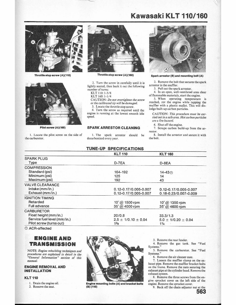
Throtlls atop screw (A)(110)
Pilot screw (A,)(180)
I. Locate the pilot screw on the side of
the carburetor.
SPARK PLUG
Type
COMPRESSION
Standard (psi)
Minimum (psi)
Maximum (psi)
VALVE CLEARANCE
Intake (mm/in.)
Exhaust (mm/in .)
IGNITION TIMING
Retarded
Full advance
CARBURETOR
Float height (mm/in.)
Service fuel level (mm/in.)
Pilot screw (turns out)
@ ACR-affected
ENGINE AND
TRANSMISSION
NOTE: Engine rebuilding techniques and
proct:durcs arc explained ill delu.il in the
"General Information" section of this
manual.
ENGINE REMOVAL AND
INSTALLATION
KLT 110
Kawasaki KLT 110/160
Throttle slop screw (A)(180)
2. Turn the screw in carefu ll y until it is
lightly seated. then back it out the following
number of turns:
KLT 11 0: 1·3 / 8
KLT 160: 1· 114
CAUTION: Do not overtighten the screw
or the calibrated tip will be damaged.
3. Locate the throttle stop screw.
4. Turn the screw as required until the
engine is running at the lowest smooth idle
speed .
SPARK ARRESTOR CLEANING
1. The spark arrestor should be
decarbonized every year.
TUNE-UP SPECIFICATIONS
KLT 110
0-7EA
164-192
125
192
Spark arr.,lor (8) and mounting bolt (A)
2. Remove the bolt that secures the spark
arrestor in the muffler.
3. Pull out the spark arrestor.
4. In an open, well-ventilated area clear
of flammable materials, start the engine.
5. When operating temperature is
reached, rev the engine while tapping the
muffler with a plastic mallet. This will dis-
lodge built-up carbon particles.
CAUTION: This procedure must be car-
ried out in a safearca. Hot carbon particles
are a fire hazard.
6. Shut off the engine.
7. Scrape carbon build-up from the ar-
restor.
8. Install the arrestor and secure it with
the bolt.
KLT160
O-SEA
14-43@
14
43
0. 12-0 .17 10.005-0.007
0.12-0.1710.005 -0 .007
0.12-0.17 10.005-0.007
0. 1S-0.23/0.007 -0.009
W@1S00rpm
35' @ 4000 rpm
2010.S
2.5 ± 1/0.10 ± 0.04
H,
10' @ 1350 rpin
35' @ 4600 rpm
33.3/1.3
5.0 ± 1/0.20 ± 0.04
1'14
3. Remove the rear fender.
4. Remove the gas tank. See "Fuel
Systems."
5. Remove the carburetor. See "Fuel
Systems."
6. Remove the air cleaner case.
7. Loosen the muffler clamp on the ex-
haust pipe. Remove the muffler bracket bolts
on the fra me. Remove the nuts securing the
exhaust pipe at the cylinder head. Remove the
exhaust system.
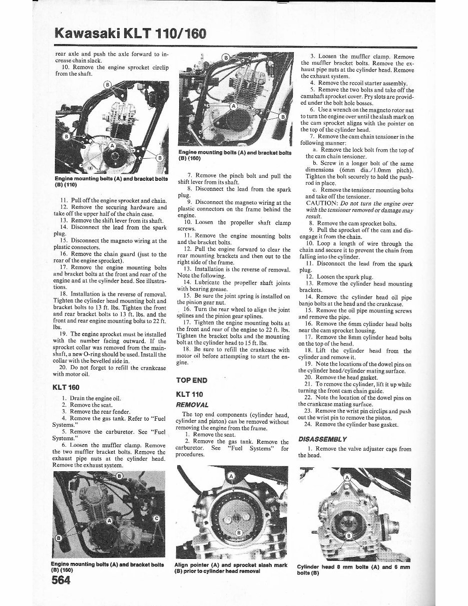
1. Drain the engine oil. Engine mounting bolta (A) and bracket bolla
8. Remove the three screws from the en-
gine sprocket cover on the left sid e of the
engine. Remove the sprocket cover.
2. Remove the seat. (B) (110) 9. Back off the chain adjuster nut at the
563
Kawasaki KL T 110/160
rear axle and push the axle forward to in-
crease chain slack.
10. Remove the engine sprocket circlip
from the shaft.
Engine mounting bolt, (A) and bracket bolt.
(8) (110)
11. Pull off the engine sprocket and cha in .
12 . Remove the securing hardware a nd
take off the upper half of the chain case.
13. Remove the shift lever from its shaft.
14. Di sconnect the lead from the spark
plug.
15. Disconnect the magneto wiring at the
plastic connectors.
16 . Remove the chain guard Uust to the
rear of the engine sprocket).
17. Remove the engine mounting bolts
and bracket bolts at the front and rear of the
engine and at the cylinder head. See illustra-
tions.
18. Installation is the reverse of removal.
Tighten the cylinder heHC{ mounting bolt and
bracket bolts to 13 ft. Ibs. Tighten the front
and rear bracket bolts to 13 ft. Ibs. and the
front and rear engine mounting bolts to 22 ft.
Ibs.
19. The engine sprocket must be installed
with the nu mber facing outward. If the
sprocket collar was removed from the main-
shaft, a new O-ring should be used. Install the
collar with the bevelled side in.
20. Do not forget to refill the crankcase
with motor oil.
KLT160
I. Drain the engine oil.
2. Remove the seat.
3. Remove the rear fender.
4. Remove the gas tank. Refer to "Fuel
Systems."
5. Remove the carburetor . See "Fuel
Systems."
6. Loosen the muffler clamp. Remove
the two muffler bracket bolts. Remove the
exhaust pipe nuts at the cylinder head.
Remove the exhaust system.
, .... ", --- ,- ..... ,
Engine mounting bolts (A) and bracket bolls
(8)(160)
564
Engine mounting bolt' (A) and bracket bolt,
(8)(160)
7. Remove the pinch bah and pull the
shift lever from its shaft.
S. Disconnect the lead from the spark
plug.
9. Disconnect the magneto wiring at the
plastic connectors on the frame behind the
engine.
10. Loosen the propeller shaft clamp
screws.
I I. Remove the engine mounting bolts
and the bracket bolts.
12. Pull the engine forward to clear the
rear mounting brackets and then out to the
right side of the frame.
13. Installation is the reverse of removal.
Note the following.
14. lubricate the propeller shaft joints
with bearing grease.
I S. Be sure the joint spring is in stalled on
the pinion gcar nut.
16. Turn the rear wheel to a lign the joint
splines and the pinion gear splines.
17. Tighten the engine mounting bolts at
the front and rear of the engine to 22 ft. Ibs.
Tighten the bracket bolts and the mounting
bolt at the cylinder head to IS ft.lbs .
IS. Be sure to refill the crankcase with
motor oil before attempti ng to sta rt the en-
gine.
TOP END
KLT 110
REMOVAL
The top end components (cylinder head,
cylinder and piston) can be removed without
removing the engine from the frame.
I. Remove the seat.
2. Remove the gas tank. Remove the
carburetor . See "Fuel Systems" for
procedures.
Align poinler (A) and sprocket 'lash mark
(8) prior to cylinder head removal
3. Loosen the muffler clamp. Remove
the muffler bracket bolts. Remove the ex-
hawn pipe nuts at the cylinder head. Remove
the exhaust system.
4. Remove the recoil st arter assembly.
5. Remove the two bolts and take off the
cams haft sprocket cover. Pry slots are provid-
ed under the bolt hole bosses.
6. Use a wrench on the magneto rotor nut
to turn the engine over until the slash mark on
the cam sprocket aligns with the pointer on
the top of the cylinder head.
7. Remove the cam chain tensioner in the
following manner:
a. Remove the lock bolt from the top of
the cam chain tensioner.
b. Screw in a longer bolt of the same
dimensions (6mm dia .l l.Omm pitch).
Tighten the bolt securely to hold the push·
rod in place.
c. Remove the tensioner mounting bolts
and take orf the tensioner.
CAUTION: Do not turn the engine over
with the tcnsioner removed or damage may
result.
S. Remove the cam sprocket bolts.
9. Full the sprocket off the cam and dis-
engage it from the chain.
10. Loop a length of wire through the
chain and secure it to prevent the chain from
falling into the cylinder.
II . Disconnect the lead from the spark
plug.
12 . Loosen the spark plug.
13. Remove the cylinder head mounting
brackets.
14. Remove the cylinder head oi l pipe
banjo bolts at the head and the crankcase.
15. Remove the oil pipe mounting screws
and remove the pipe.
16. Remove the 6mm cylinder head bolts
near the cam sprocket housing.
17. Remove the Smm cylinder head bolts
on the topof the head.
18. Lift the cylinder head from the
cylinder and remove it.
19. Note the locations of the dowel pins on
the cylinder head/ cylinder mating surface.
20. Remove the head gasket.
21. To remove the cylinder, lift it up while
turning the front cam chain guide.
22. Note the location of the dowel pins on
the crankcase mating s urface.
23. Remove the wrist pin circlipsand push
out the wrist pin to remove the piston.
24. Remove the cylinder base gasket.
DISASSEMBL Y
1. Remove the valve adjuster caps from
the head.
Cylinder head 8 mm bolt, (A) and 8 mm
boll,(B)
You're Reading a Preview
What's Included?
Fast Download Speeds
Online & Offline Access
Access PDF Contents & Bookmarks
Full Search Facility
Print one or all pages of your manual
$33.99
1984-1986 KLT110 KLT160 KLT 110 160 Service & Repair Manual
Viewed 69 Times Today

What's Included?
Fast Download Speeds
Online & Offline Access
Access PDF Contents & Bookmarks
Full Search Facility
Print one or all pages of your manual
$33.99

Secure transaction
What's Included?
Fast Download Speeds
Online & Offline Access
Access PDF Contents & Bookmarks
Full Search Facility
Print one or all pages of your manual
Complete service repair manual for the KLT110 & KLT160 KLT 110 160 1984-1985-1986. No shipping involved and you can get it right away! This manual is what the dealerships use to fix your ATV. It covers all the topics like Engine, General Information, Transmission, Chassis, Lightning, Steering, Seats System, Clutch, Suspension, Locks, Brakes, Lubrication, Electrical, Frame Fuel System, Battery, and other topics. These manuals are in Adobe Acrobat format and will work on a PC or Mac. Instant delivery means no waiting for a CD to arrive via snail mail. This manual is useful for both professional mechanics and DIY enthusiasts. Get it now!


